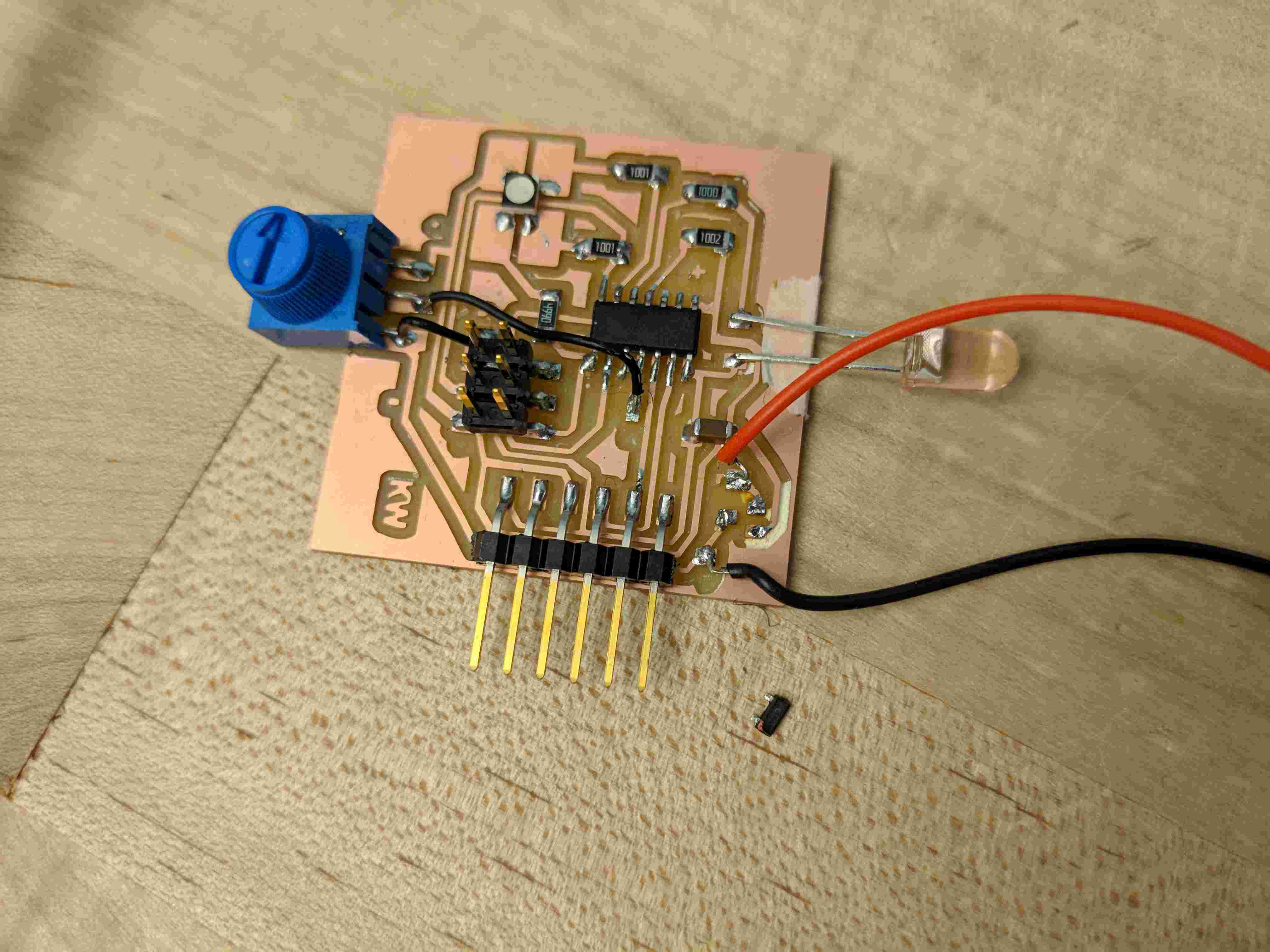
This week we had to get two boards to talk to each other, which of course involved designing and fabricating two new boards (most of my old ones are broken by now) and programming them to communicate. Naturally, the architecture shop was packed all week and we had a slew of problems with supply shortages and mills not working, but somehow I still managed to get two boards made. I wanted to create an IR remote and receiver to use for my final project, so I made one board with a potentiometer controlling an IR LED (and an RGB LED indicator) and one with an IR detector connected to two of the extra bright LEDs I'm using for my final.
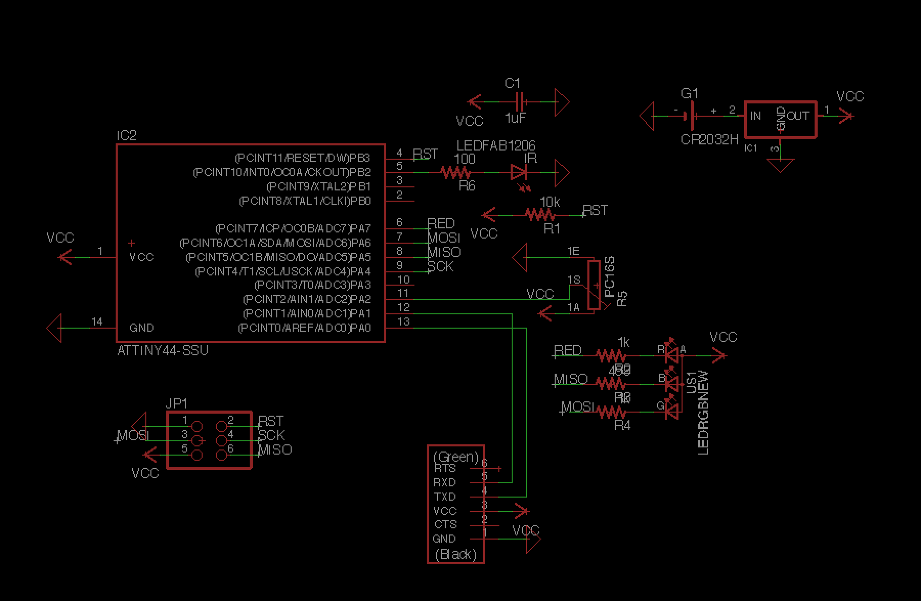
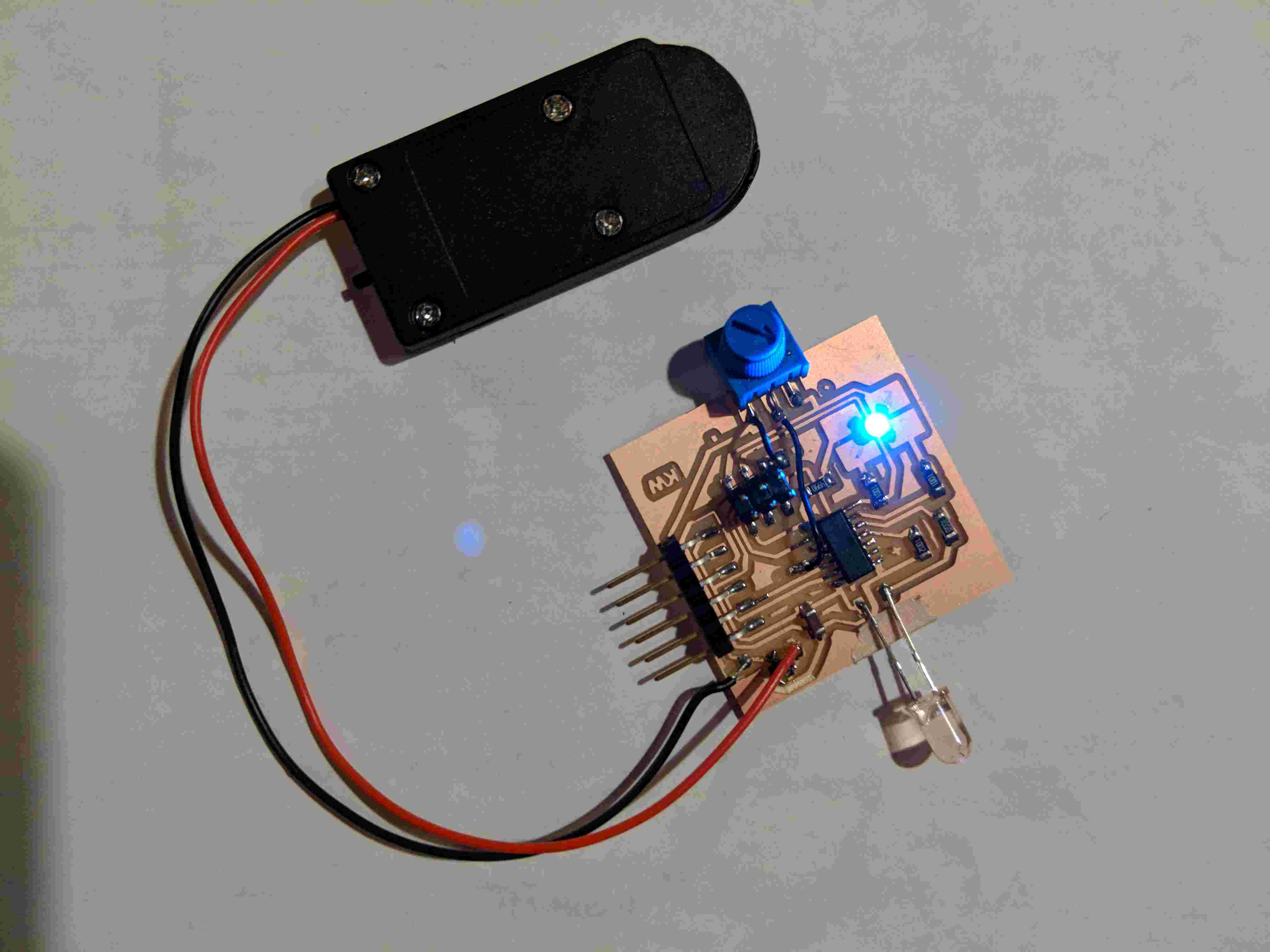
I made the two boards, troubleshooting the usual bugs like incorrectly orienting parts in Eagle or putting traces too close together (I say that like it's trivial, but of course, it took all weekend). I then went to program the boards. As soon as I plugged in the sender board, the voltage regulator started heating up. After spending a ton of time triple-checking my schematic and poking it with a multimeter, I tried it again and managed to successfully program it. However, the regulator heated up a lot and the solder joints melted. When I asked Calvin about this, he informed me that the heat was totally normal and that I probably just needed a bigger regulator. Of course, the bigger regulators required a totally different layout, so I decided to just be extra careful not to leave this board plugged in very long and switch to a bigger one for my final. I put on another regulator and managed to get it working. The regulator also seemed sufficient for the batteries, as they only produced about 6V.
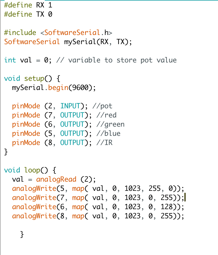
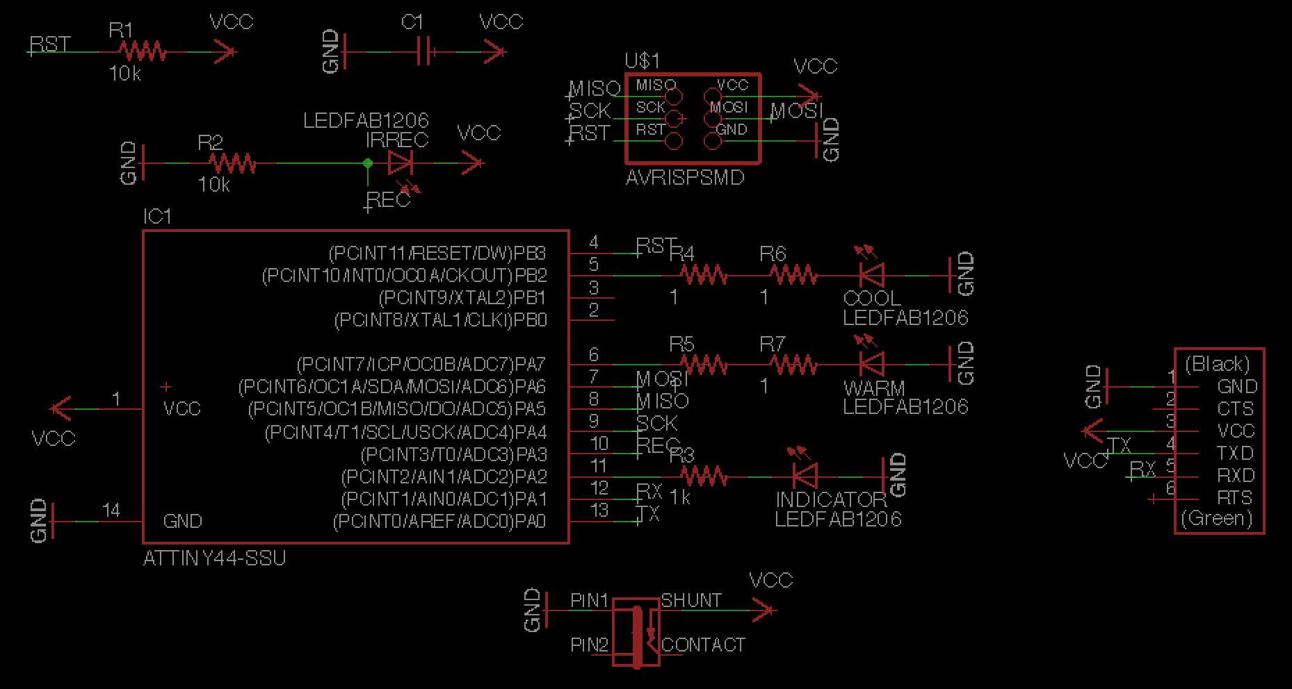
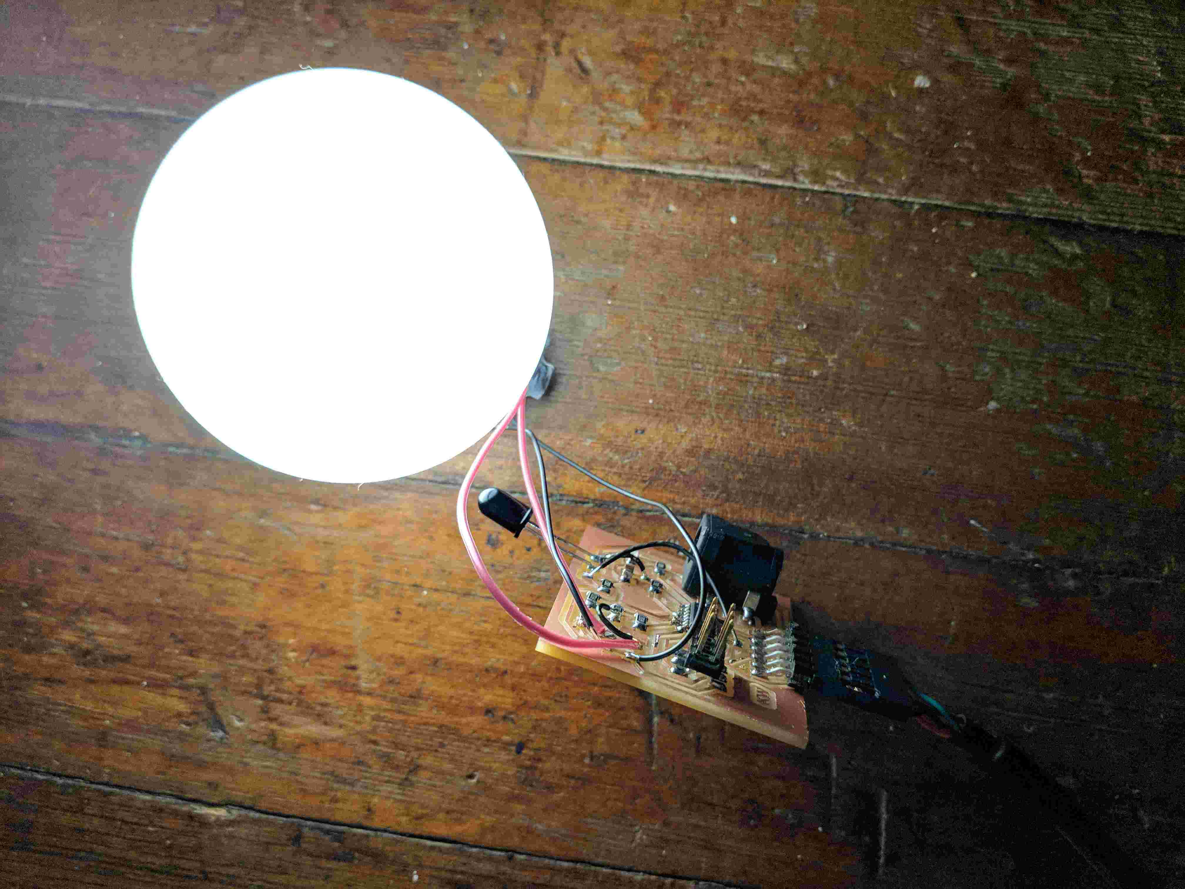
The receiver board required a bit more work to design, as I had to figure out the power and resistor needs of my fancy new LEDs. After reading the data sheets and doing some back of the napkin math, I determined that they would drain batteries much too quickly to be reasonable lamps, so I ordered some AC to 5V DC adapters from Amazon so I could plug the board into the wall. I determined the proper jack to use, and I also calculated the resistance and determined that I needed two 1 ohm resistors per LED. I also had to figure out the IR detector. I chose the ones in the same drawer as the IR LEDs, which was a bit of a mistake in retrospect, as I later learned through Googling code that the kinds of receivers that pick up remote control signals are three-pronged and work slightly differently. I did, however, get this board working and the LEDs were pleasantly bright.
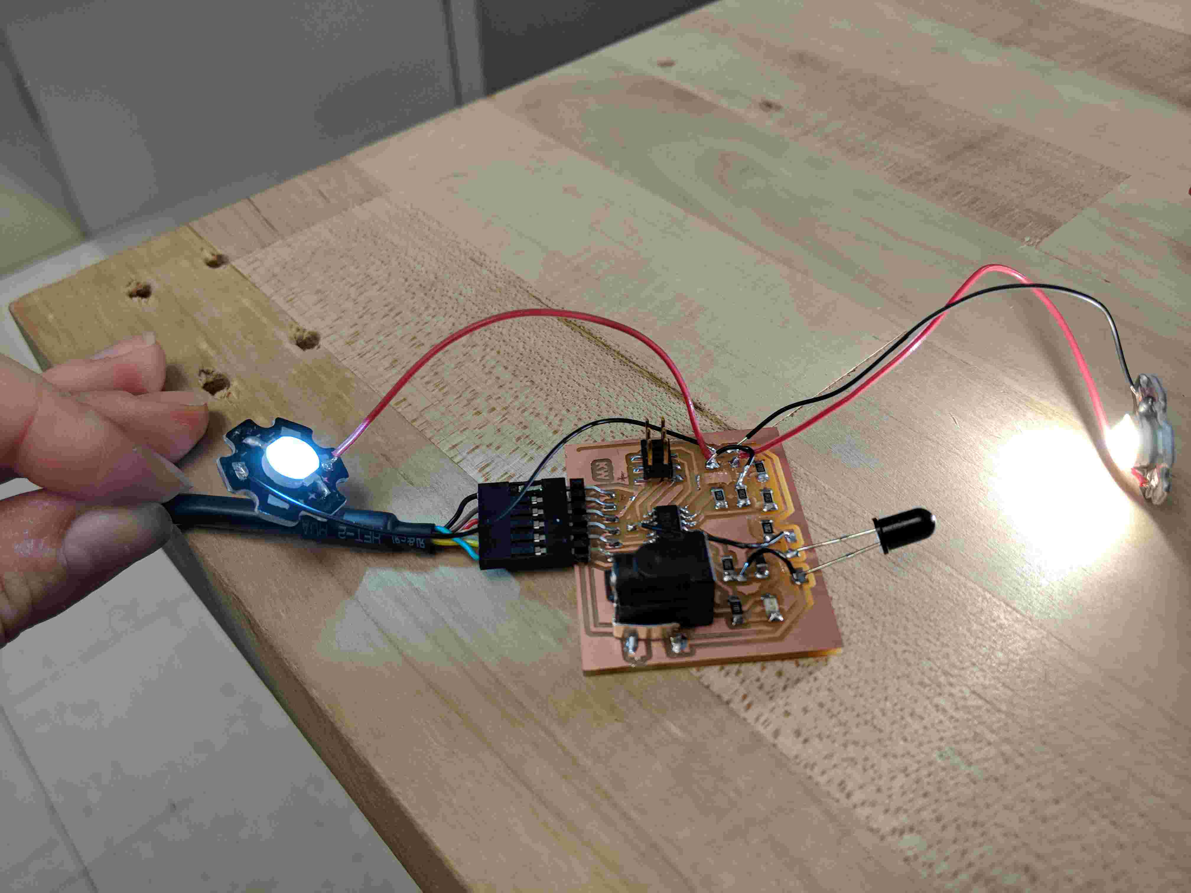

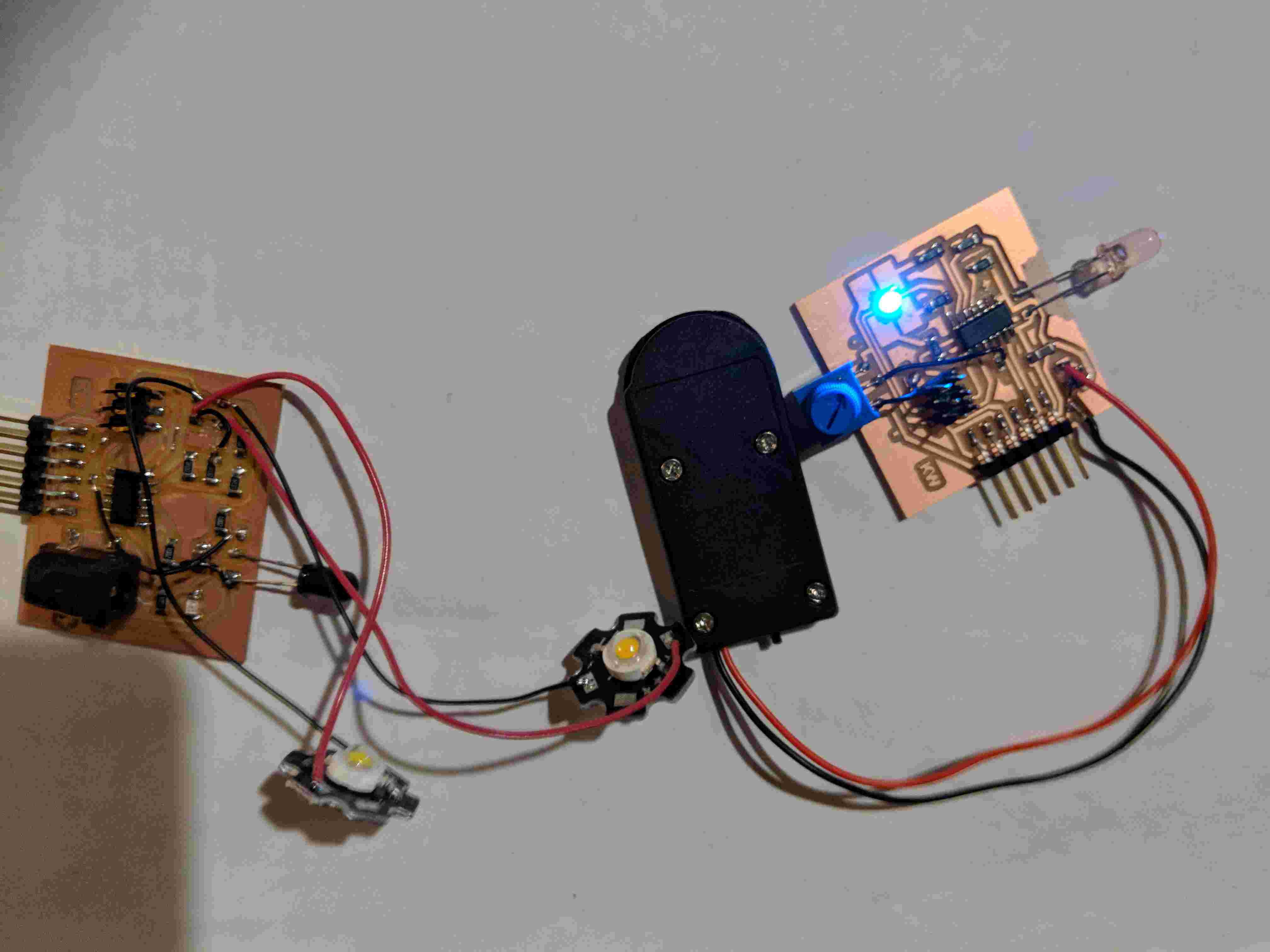
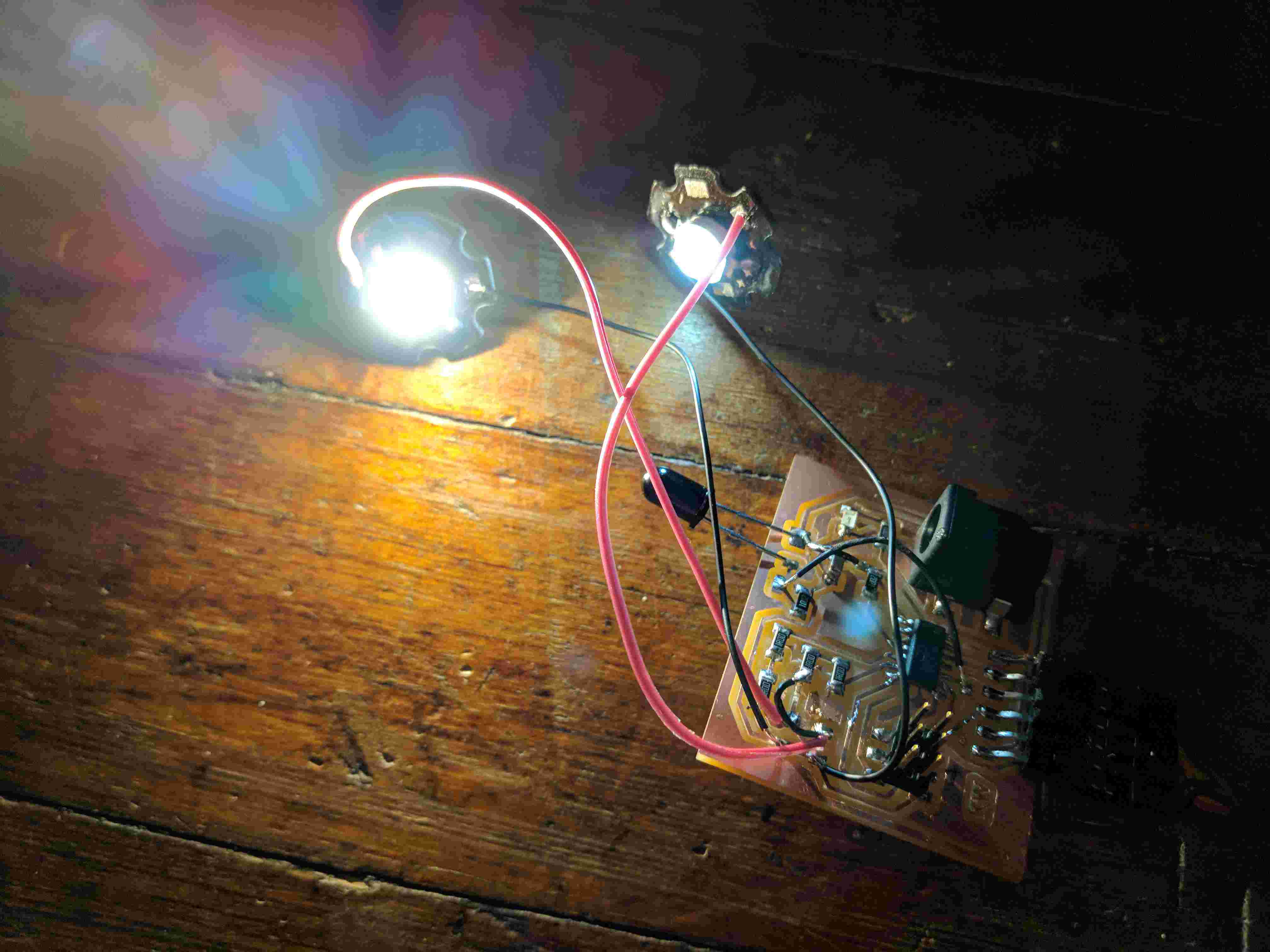
Once both boards were working, I tried to get them to talk to one another. Because I can't see the IR light, I can't tell for sure whether the IR LED was doing what I expected, but I did manage to get a reaction from the receiver board. The nature of the detector made it so that the position of the sender affected the output much more than the potentiometer value did, but I could still get a sprectrum of brightness from the cool white LED by turning the potentiometer. The indicator light and warm white LED were not responding the way I expected though, so I'll need to revisit that code when I make the boards for my final project. Overall, my boards were talking to each other about as well as I can talk to someone who exclusively speaks French (i.e. it's mostly dramatic hand-flailing).
I made the two boards, troubleshooting the usual bugs like incorrectly orienting parts in Eagle or putting traces too close together (I say that like it's trivial, but of course, it took all weekend). I then went to program the boards. As soon as I plugged in the sender board, the voltage regulator started heating up. After spending a ton of time triple-checking my schematic and poking it with a multimeter, I tried it again and managed to successfully program it. However, the regulator heated up a lot and the solder joints melted. When I asked Calvin about this, he informed me that the heat was totally normal and that I probably just needed a bigger regulator. Of course, the bigger regulators required a totally different layout, so I decided to just be extra careful not to leave this board plugged in very long and switch to a bigger one for my final. I put on another regulator and managed to get it working. The regulator also seemed sufficient for the batteries, as they only produced about 6V.
The receiver board required a bit more work to design, as I had to figure out the power and resistor needs of my fancy new LEDs. After reading the data sheets and doing some back of the napkin math, I determined that they would drain batteries much too quickly to be reasonable lamps, so I ordered some AC to 5V DC adapters from Amazon so I could plug the board into the wall. I determined the proper jack to use, and I also calculated the resistance and determined that I needed two 1 ohm resistors per LED. I also had to figure out the IR detector. I chose the ones in the same drawer as the IR LEDs, which was a bit of a mistake in retrospect, as I later learned through Googling code that the kinds of receivers that pick up remote control signals are three-pronged and work slightly differently. I did, however, get this board working and the LEDs were pleasantly bright.
Once both boards were working, I tried to get them to talk to one another. Because I can't see the IR light, I can't tell for sure whether the IR LED was doing what I expected, but I did manage to get a reaction from the receiver board. The nature of the detector made it so that the position of the sender affected the output much more than the potentiometer value did, but I could still get a sprectrum of brightness from the cool white LED by turning the potentiometer. The indicator light and warm white LED were not responding the way I expected though, so I'll need to revisit that code when I make the boards for my final project. Overall, my boards were talking to each other about as well as I can talk to someone who exclusively speaks French (i.e. it's mostly dramatic hand-flailing).