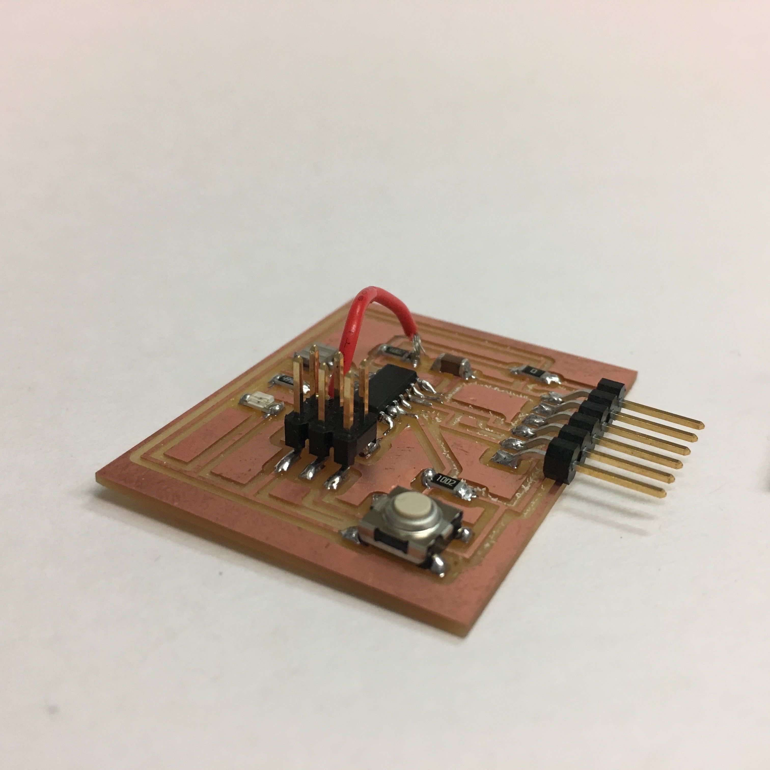
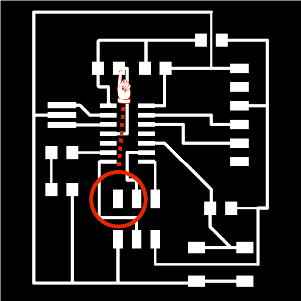
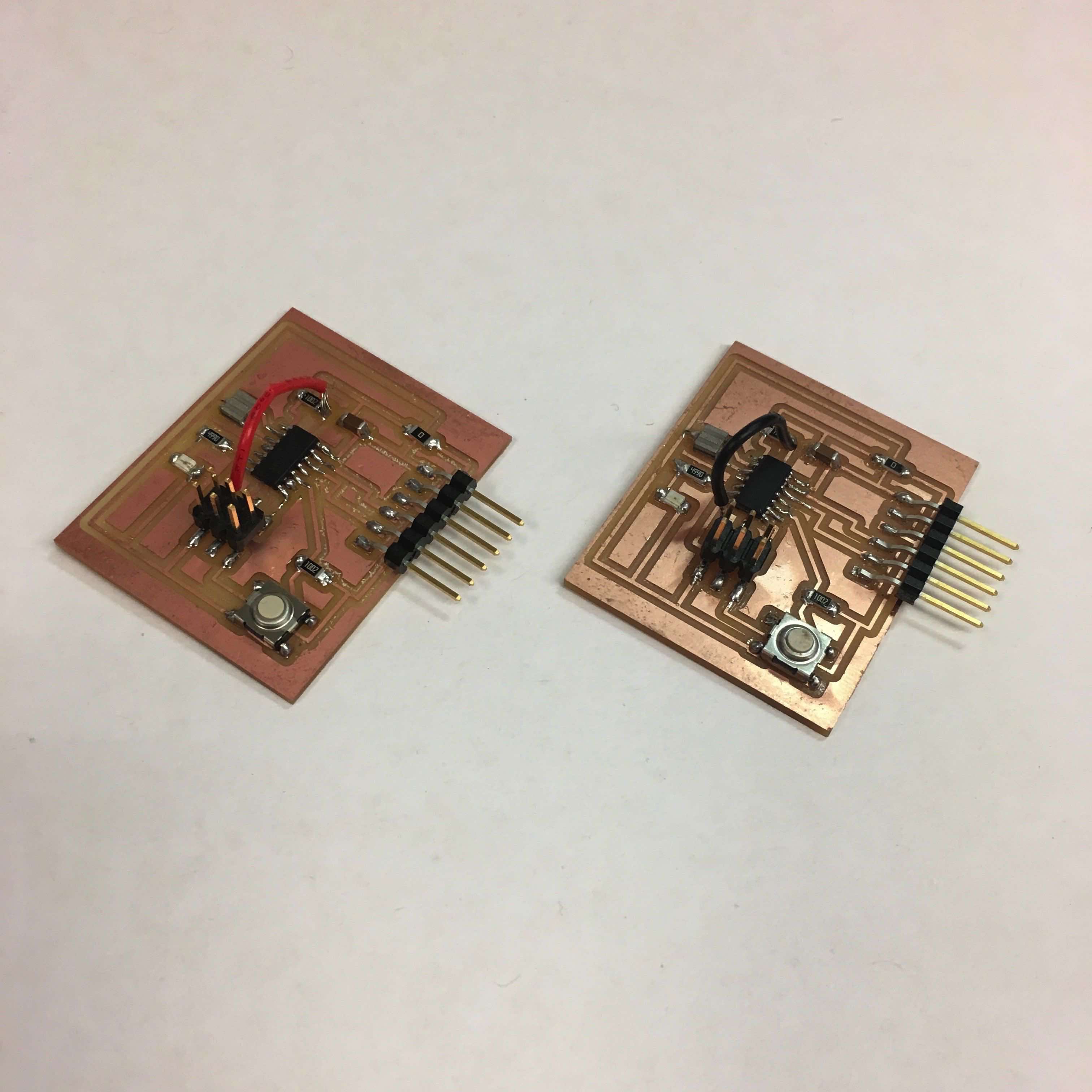
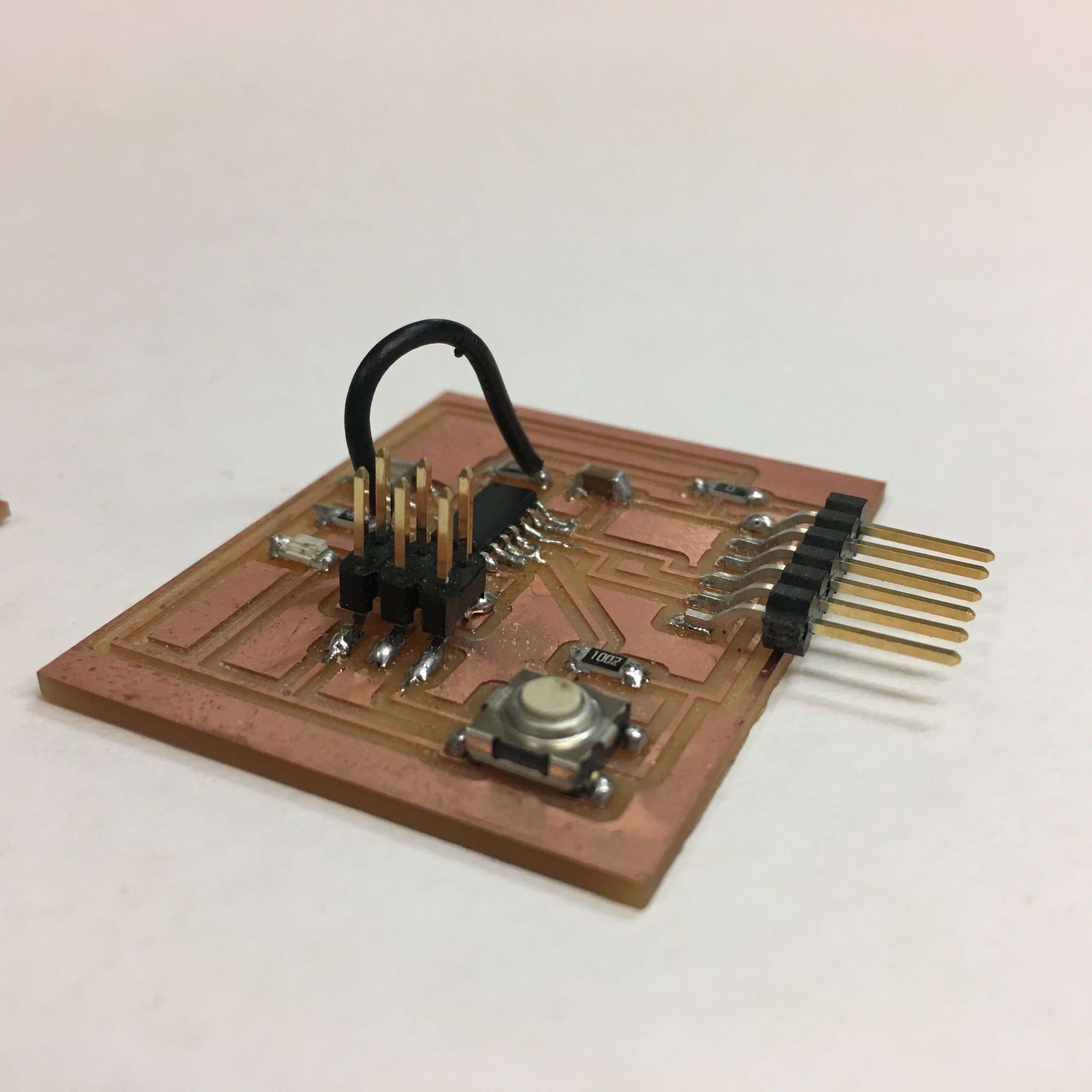
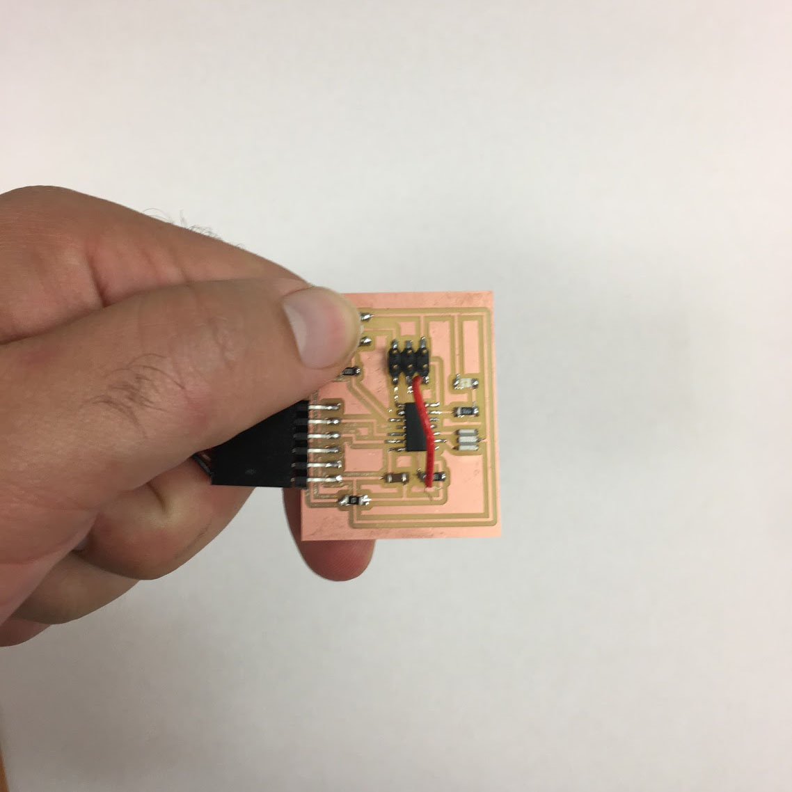
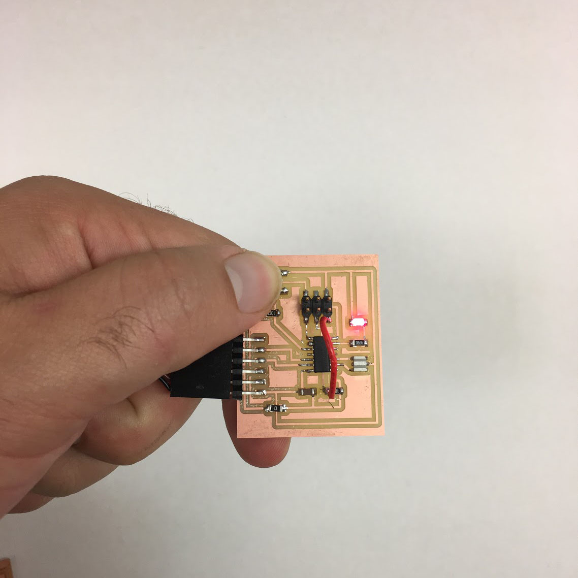
This week we programed an ATtiny44 microcontroller using the USBTiny Programmer we created from Week 03. We were asked to add a push button and LED to a modified PCB layout from Eagle. We used Eagle to add our button and a LED to the schematic. I had an issue setting up the board for programming - one of the pins was not connected correctly so I had to fuse a wire which jumped over the ATTiny44 to the correct resister.
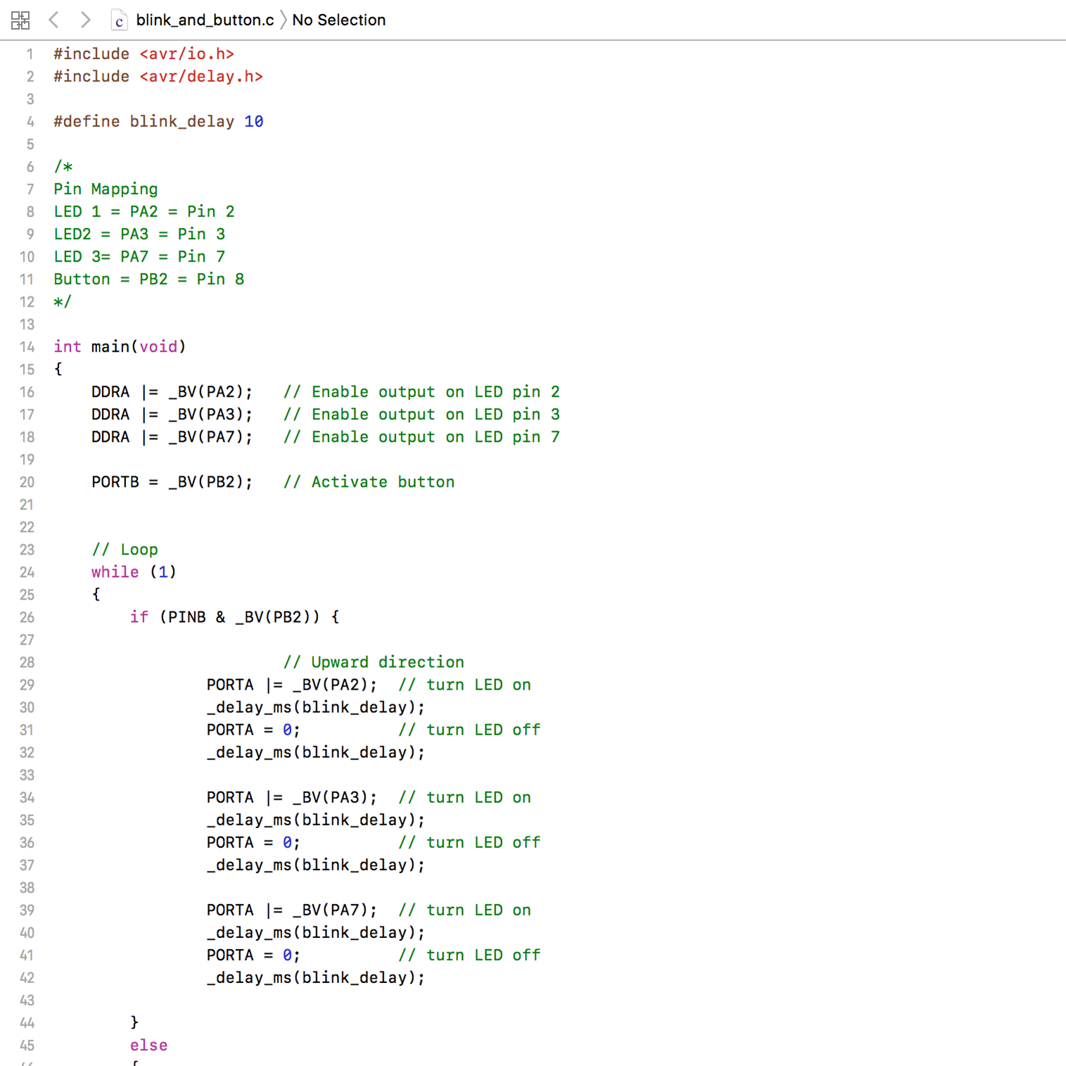
Programming the board was a bit of a nightmare - all of this is foreign to me and I relied on websites of previous years for the information. The .c, .make, and .hex business. The code you write is saved as a .c file. I used TextEditor
to write and edit my code. With the .c file you need to create a .make, file which includes a
compilation of program commands that translate your code (.c files) into machine code
(.hex files) for the microcontroller. This is the code I used from Kelly Shaw in the HTMAAA 2011 class: // LED Button Blink Program
#include
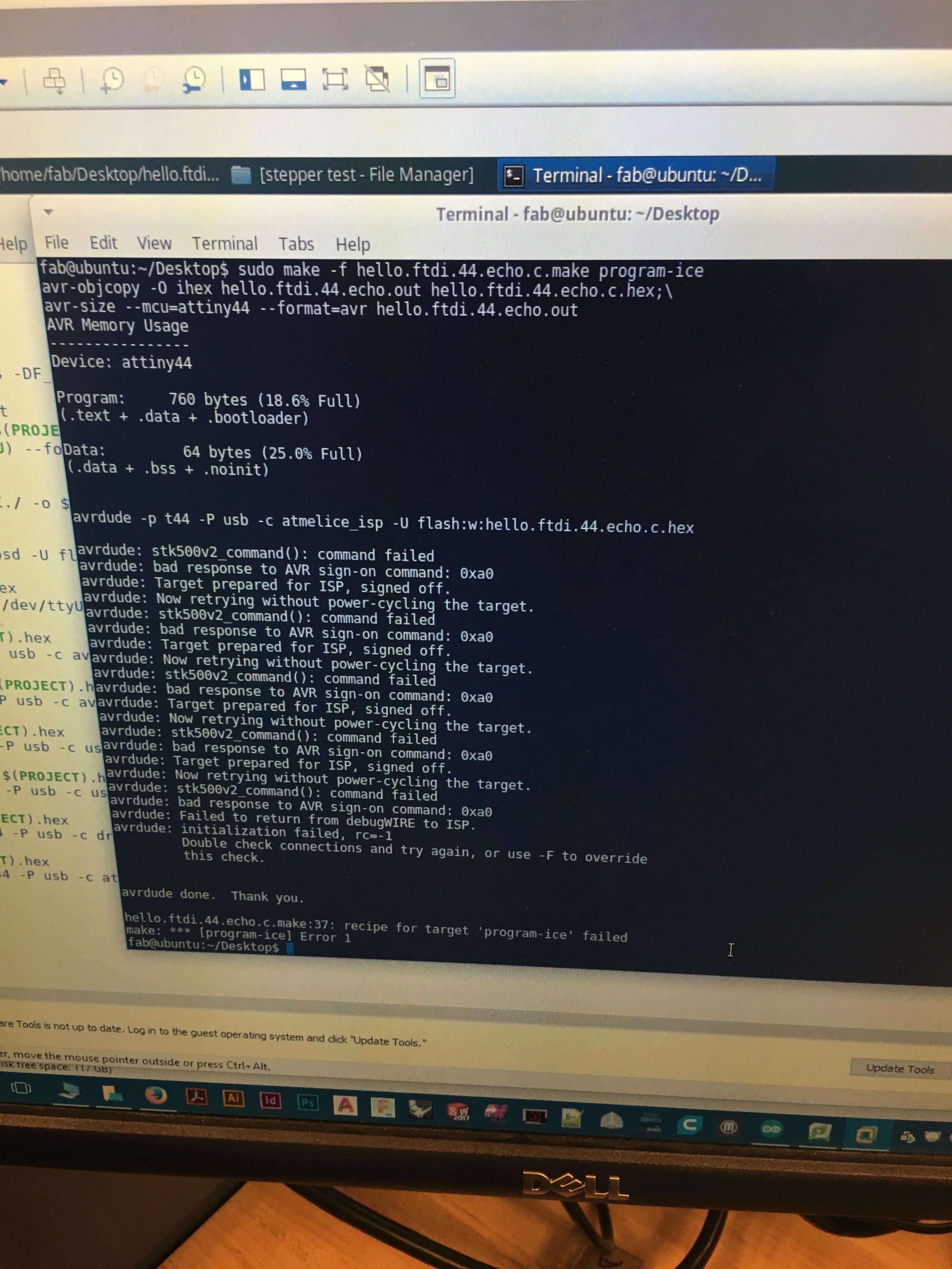
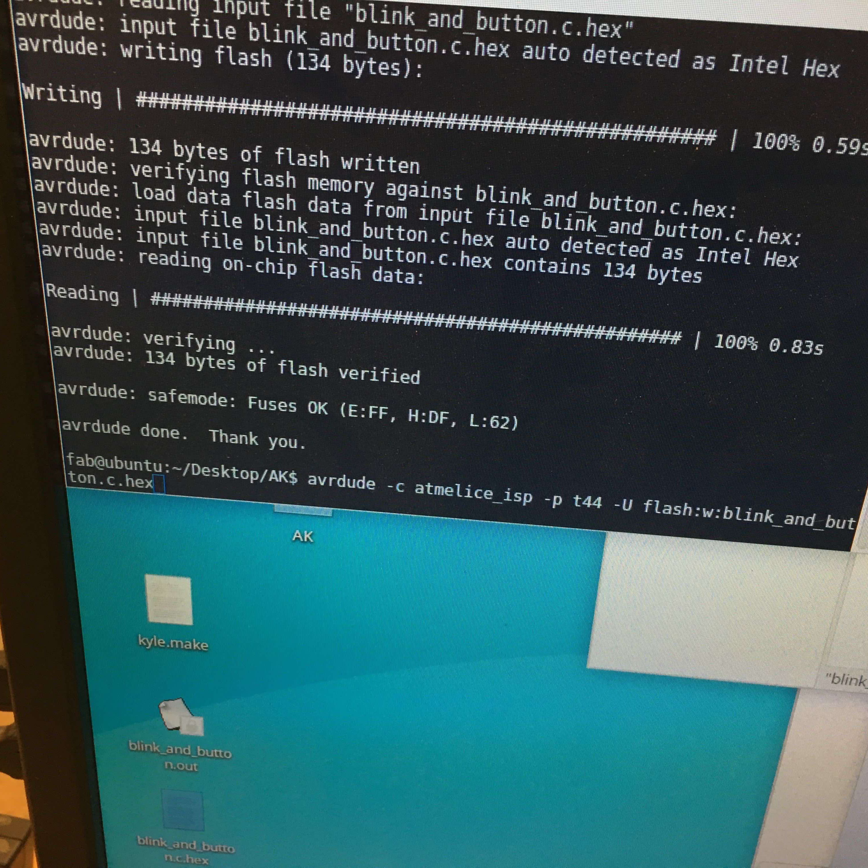
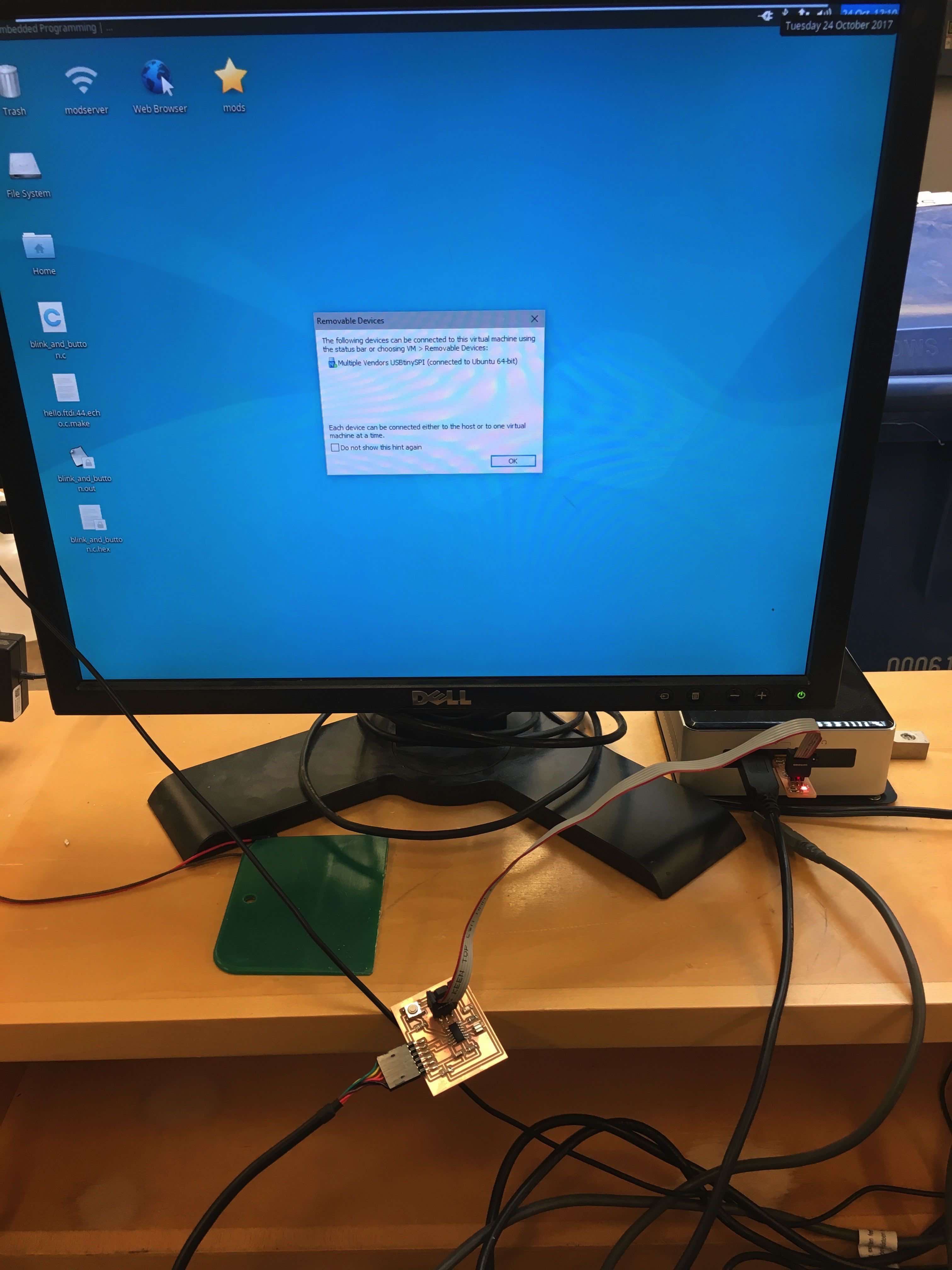
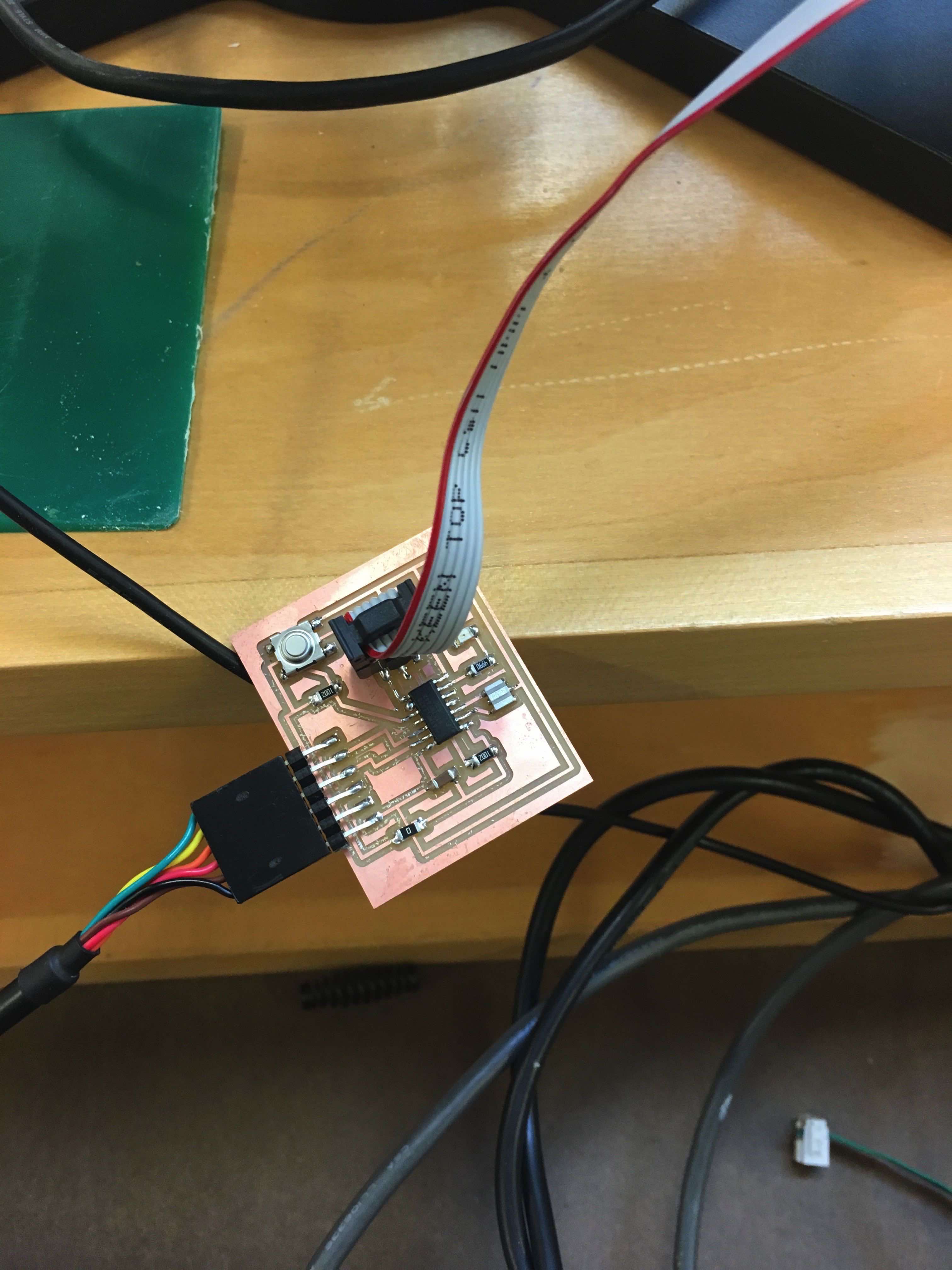
It was a long and tedious process, nothing seemed to work - eventually with the help of Justin and Paloma we were able to trouble shoot some of the issues and install a program to get the board to blink.