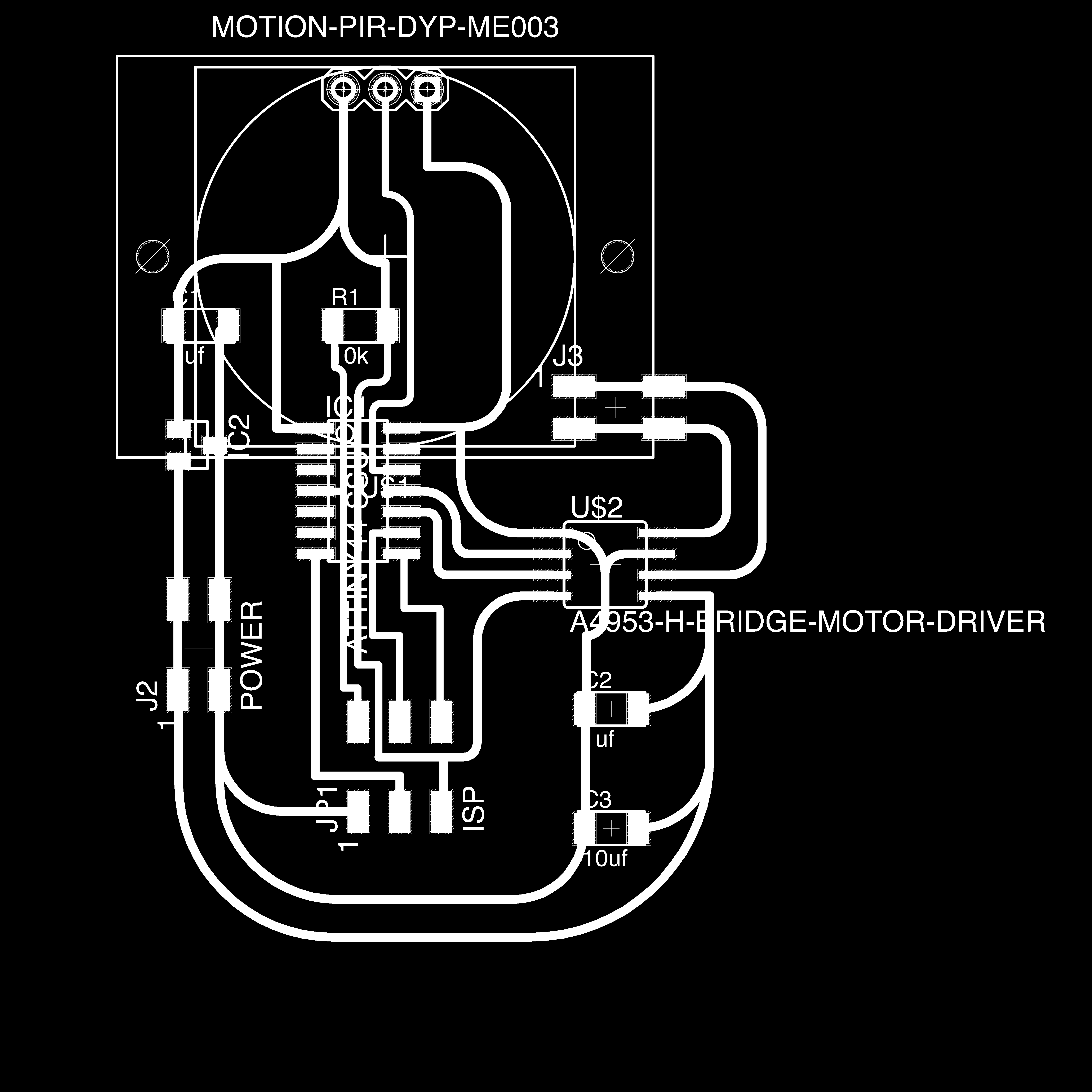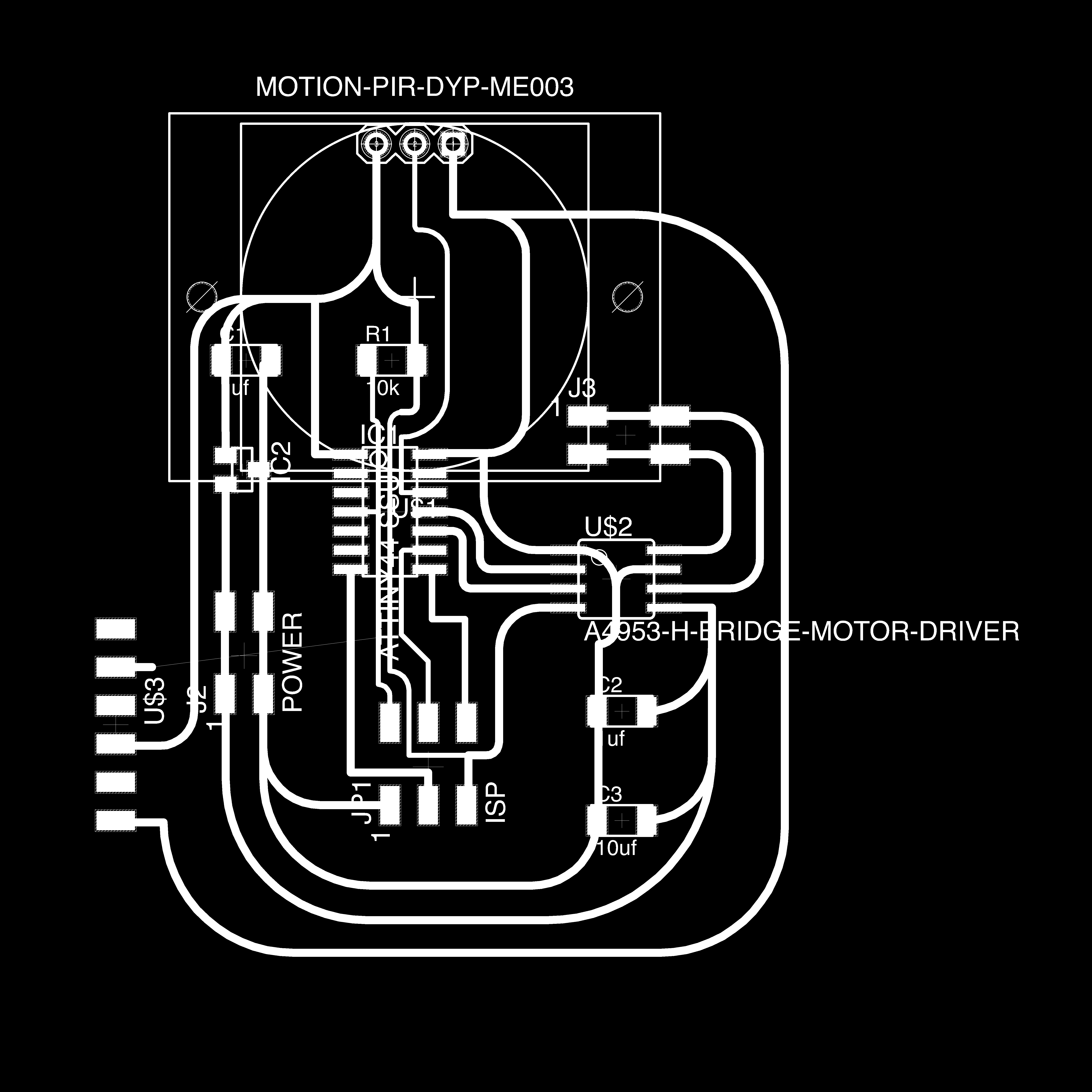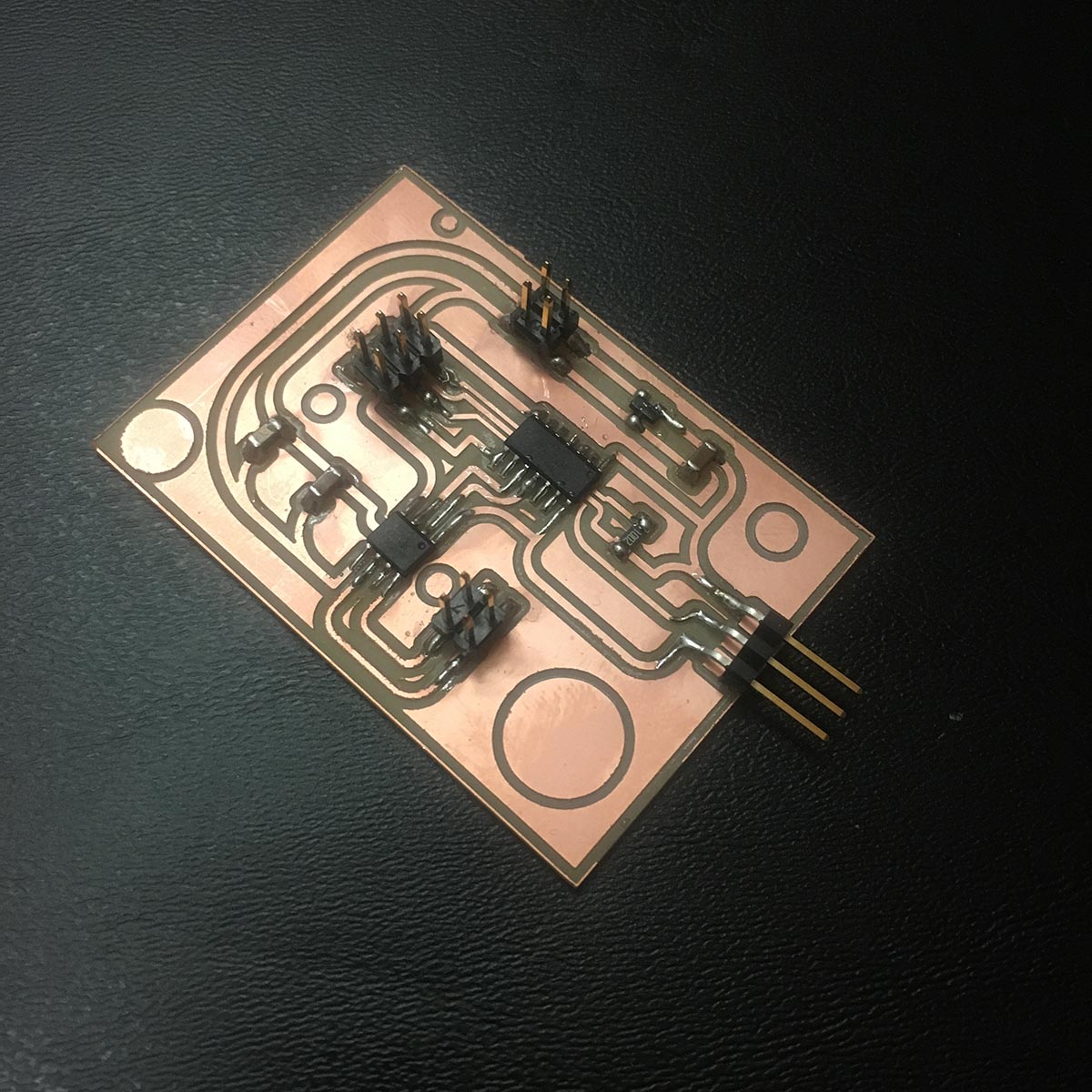
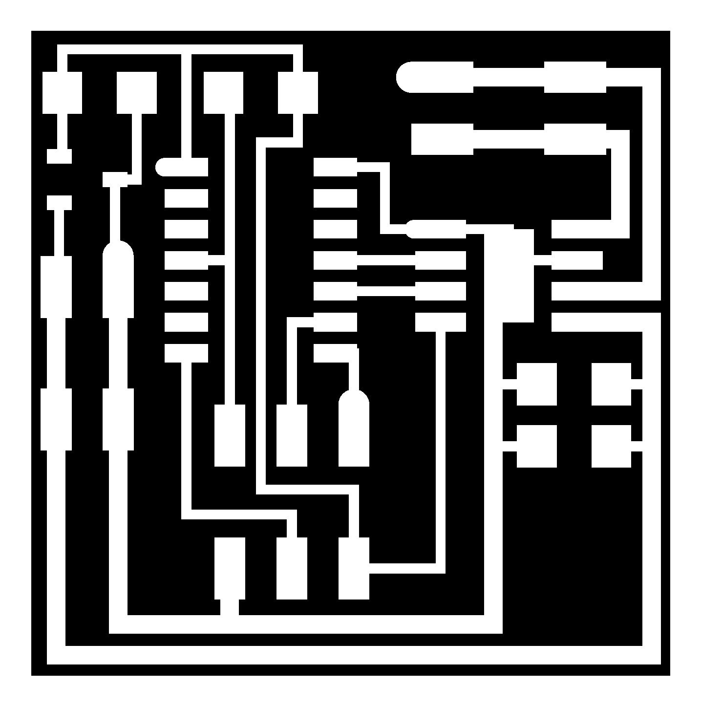
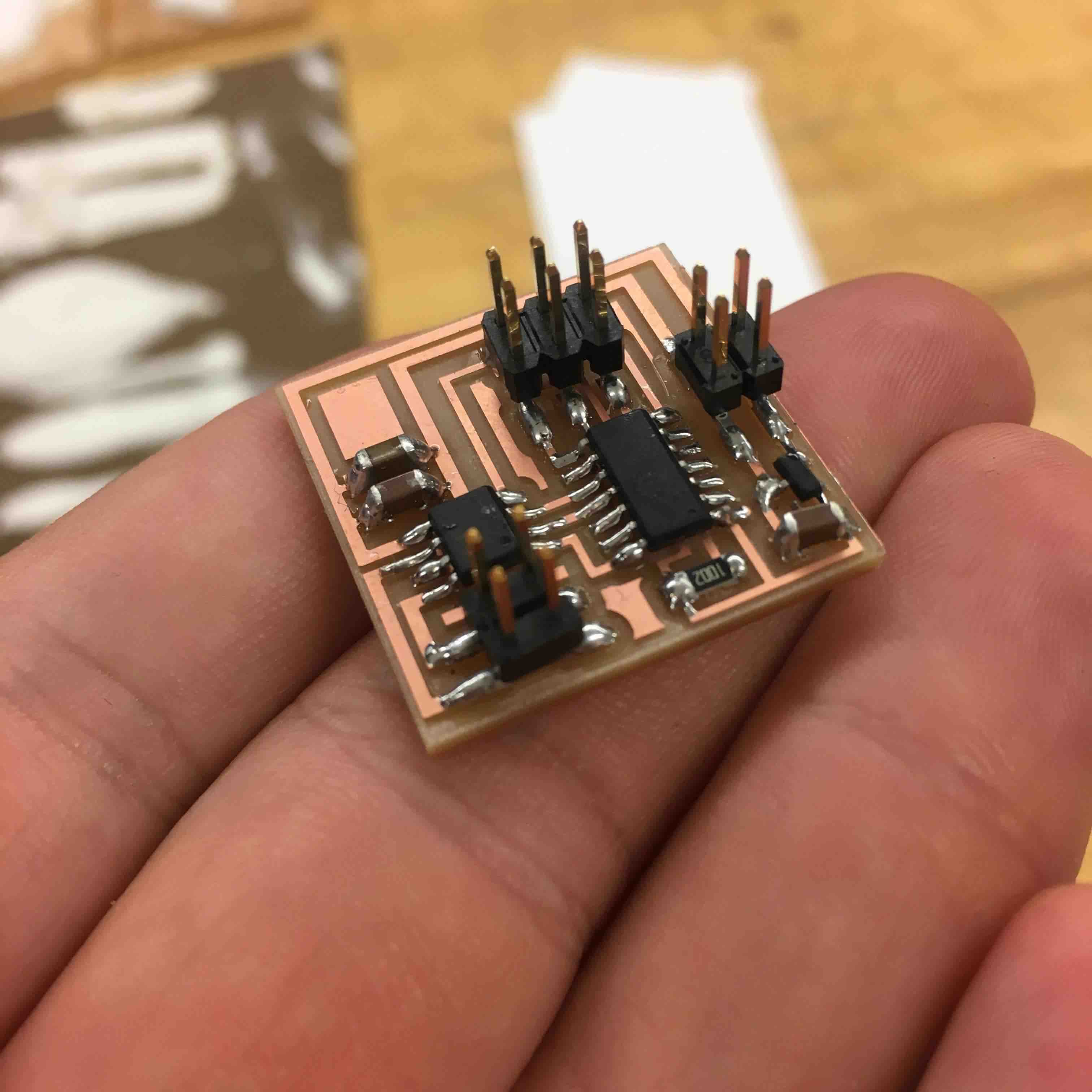
This week was output devices - looking ahead to my final project - I know I want to use a DC motor, so the first step was to test Neil's DC motor board, and the later step was to Redesign the board for my final project. I begain my milling out and soldering the example board for the DC motor. This board is quite unique as it doesn't really read into the serial port - and it is power externally by a battery. It is also so small -
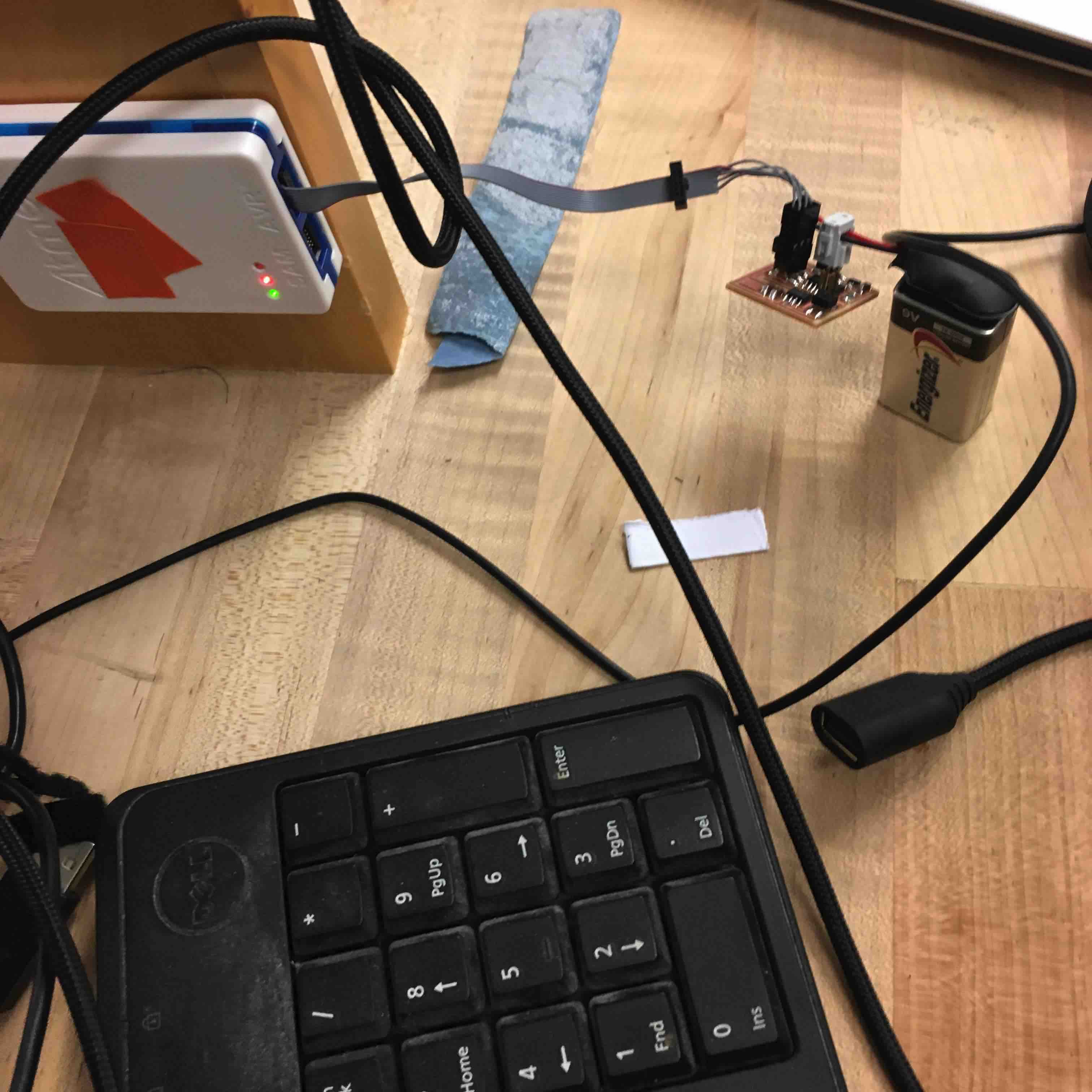
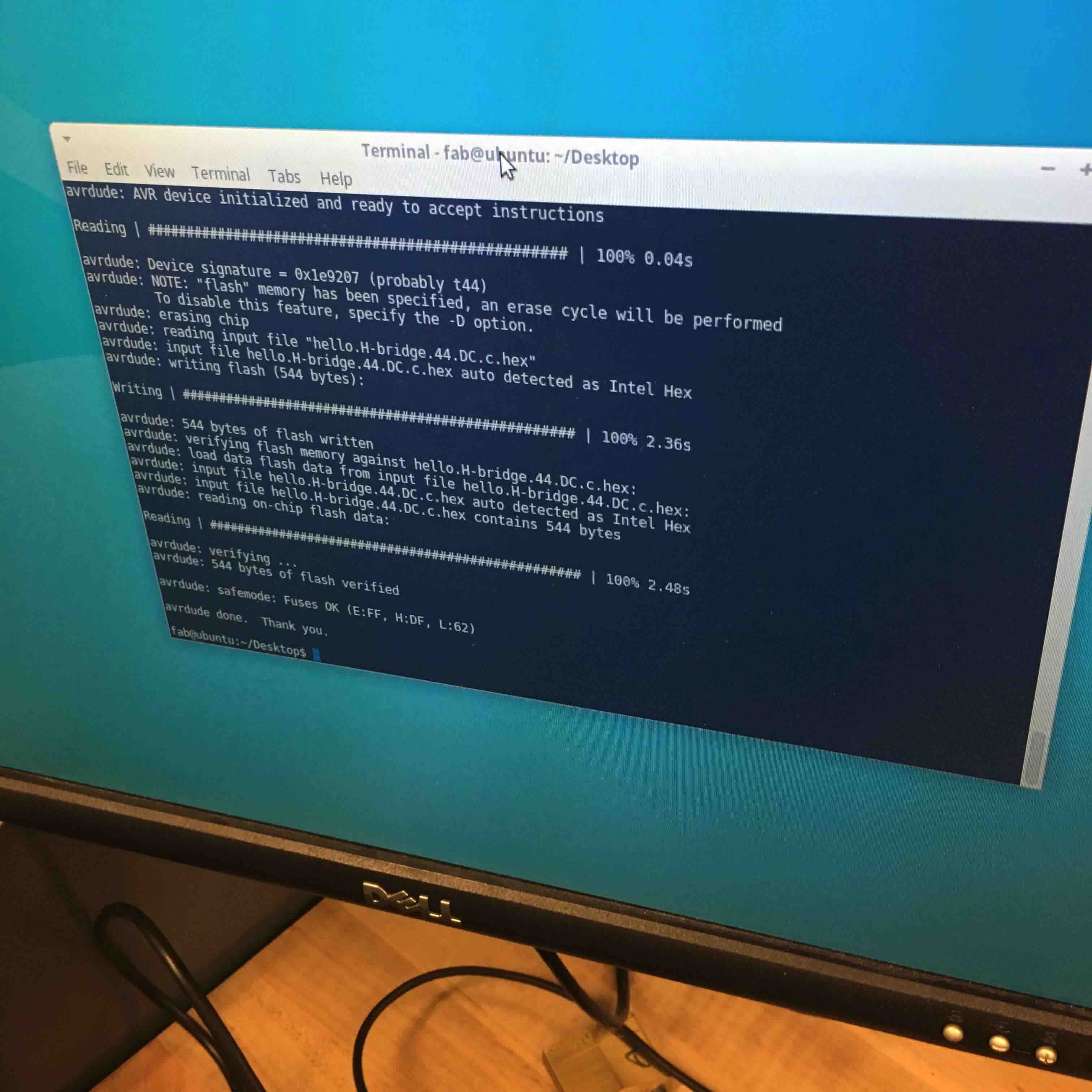
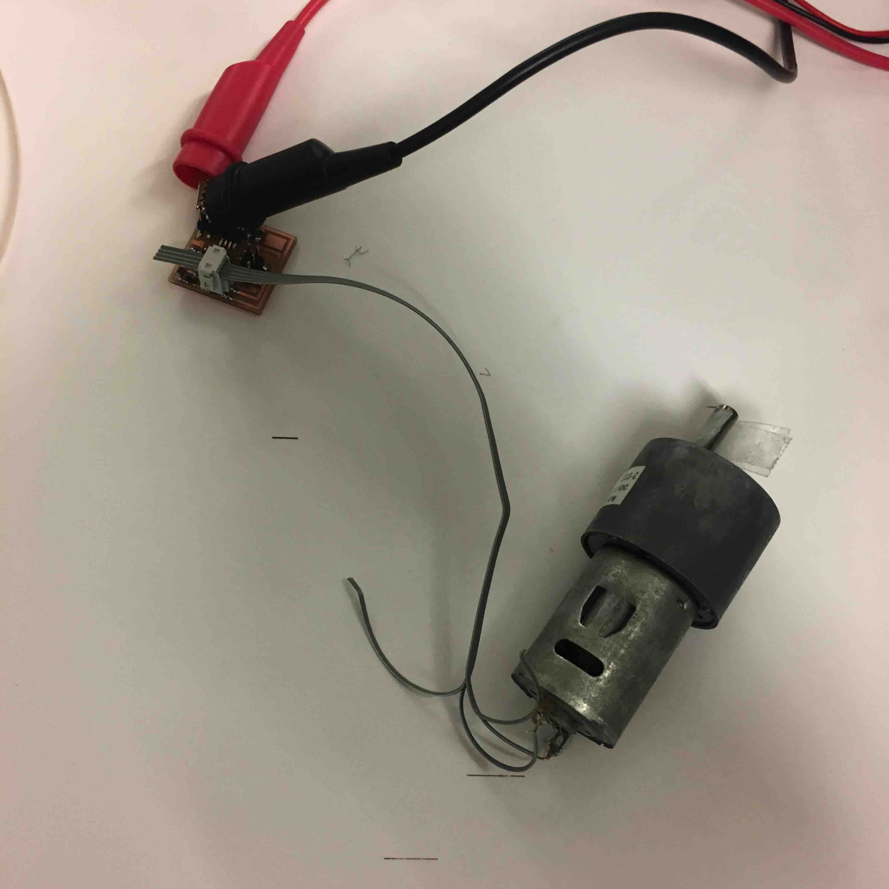
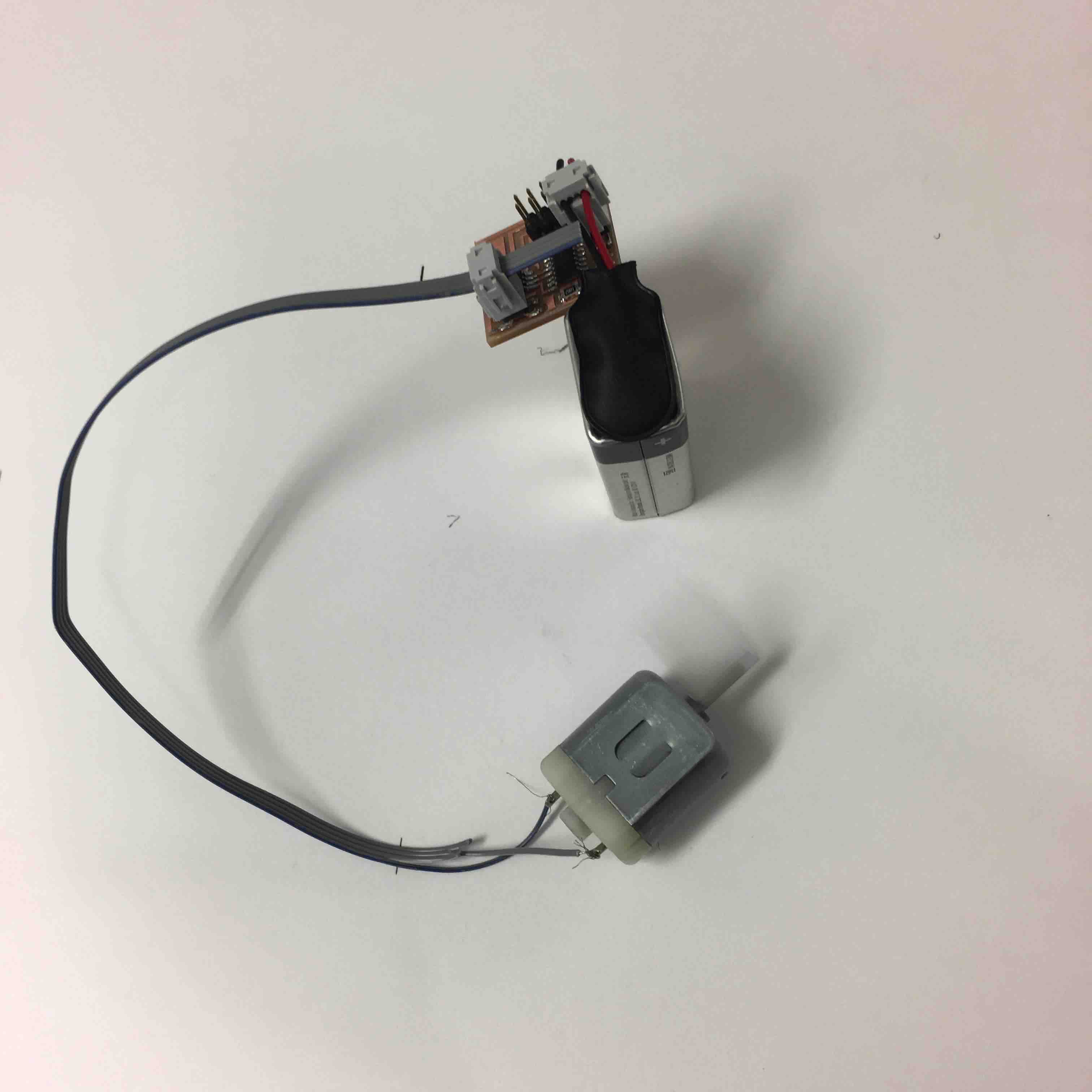
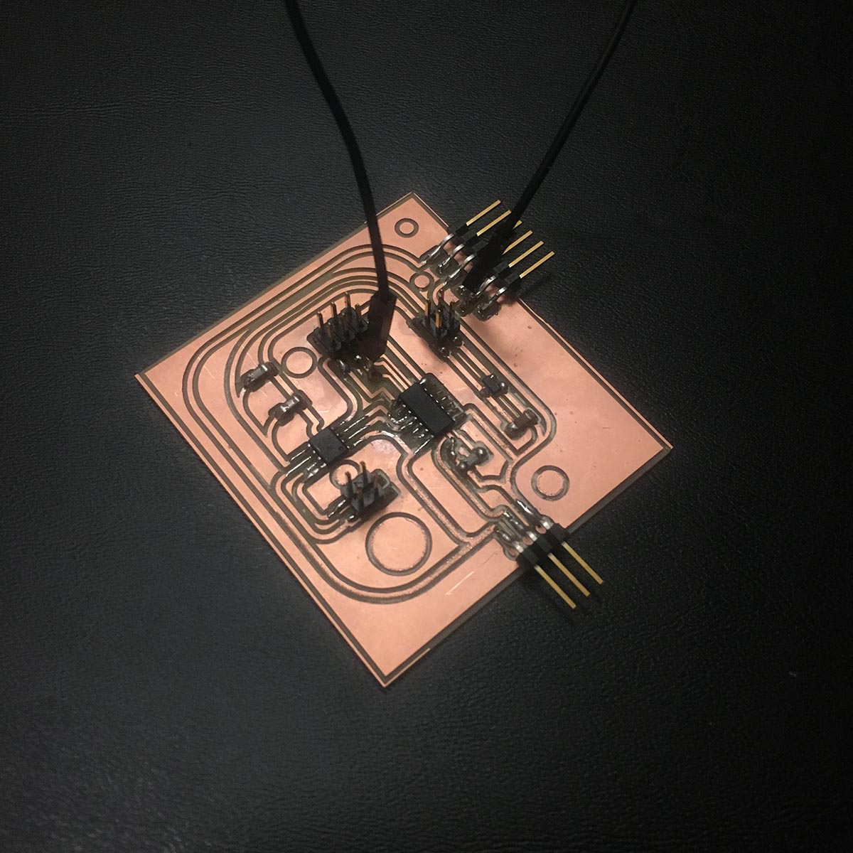
In order to program the board you must attach a battery - it is the only way the board gets power (to my understanding - and perhaps I am completely wrong now that I think of it). Anyways we did attach a battery to program the board. And luckily everything worked and the board programmed. The next step was attaching a DC motor to the board along with the battery to see if it spins.
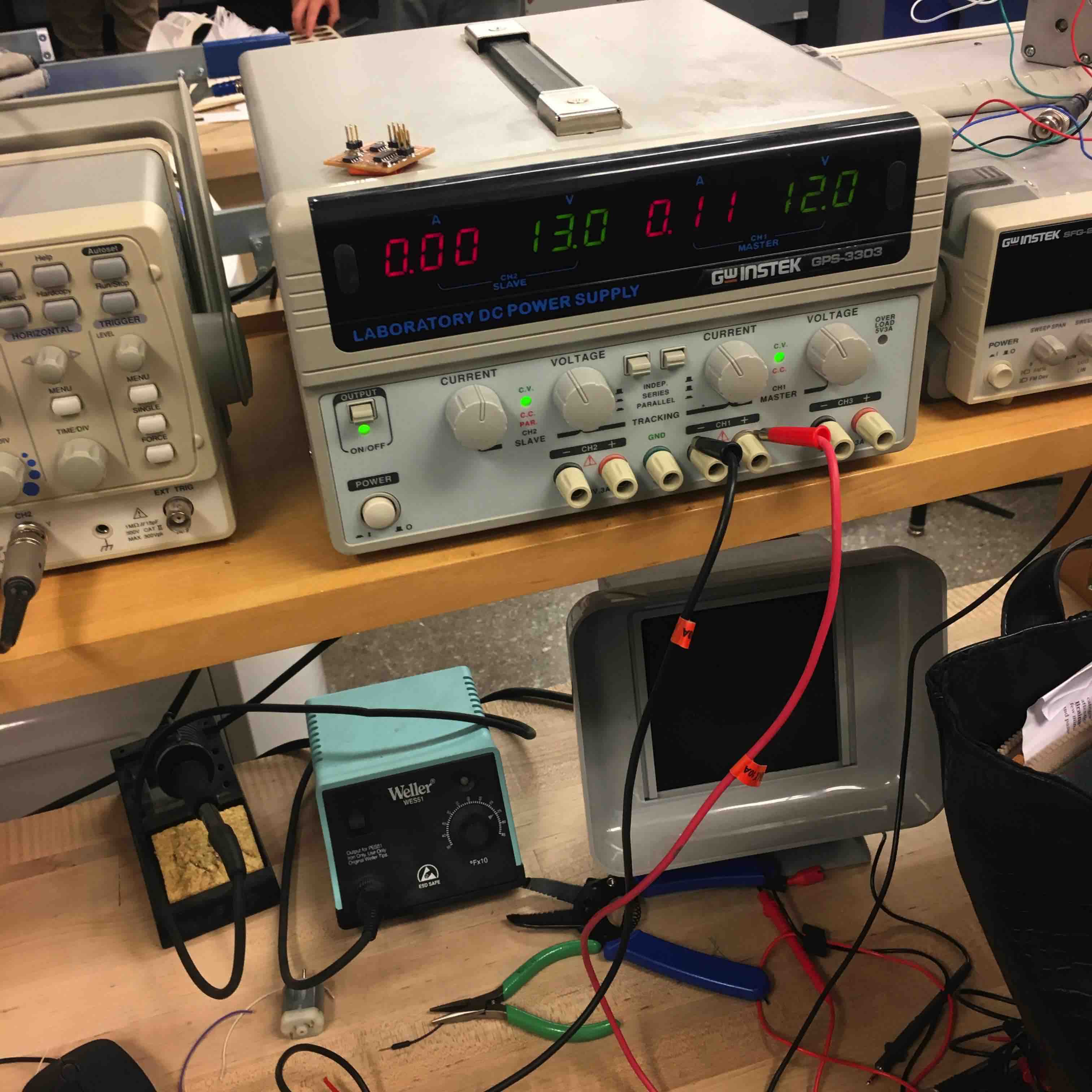
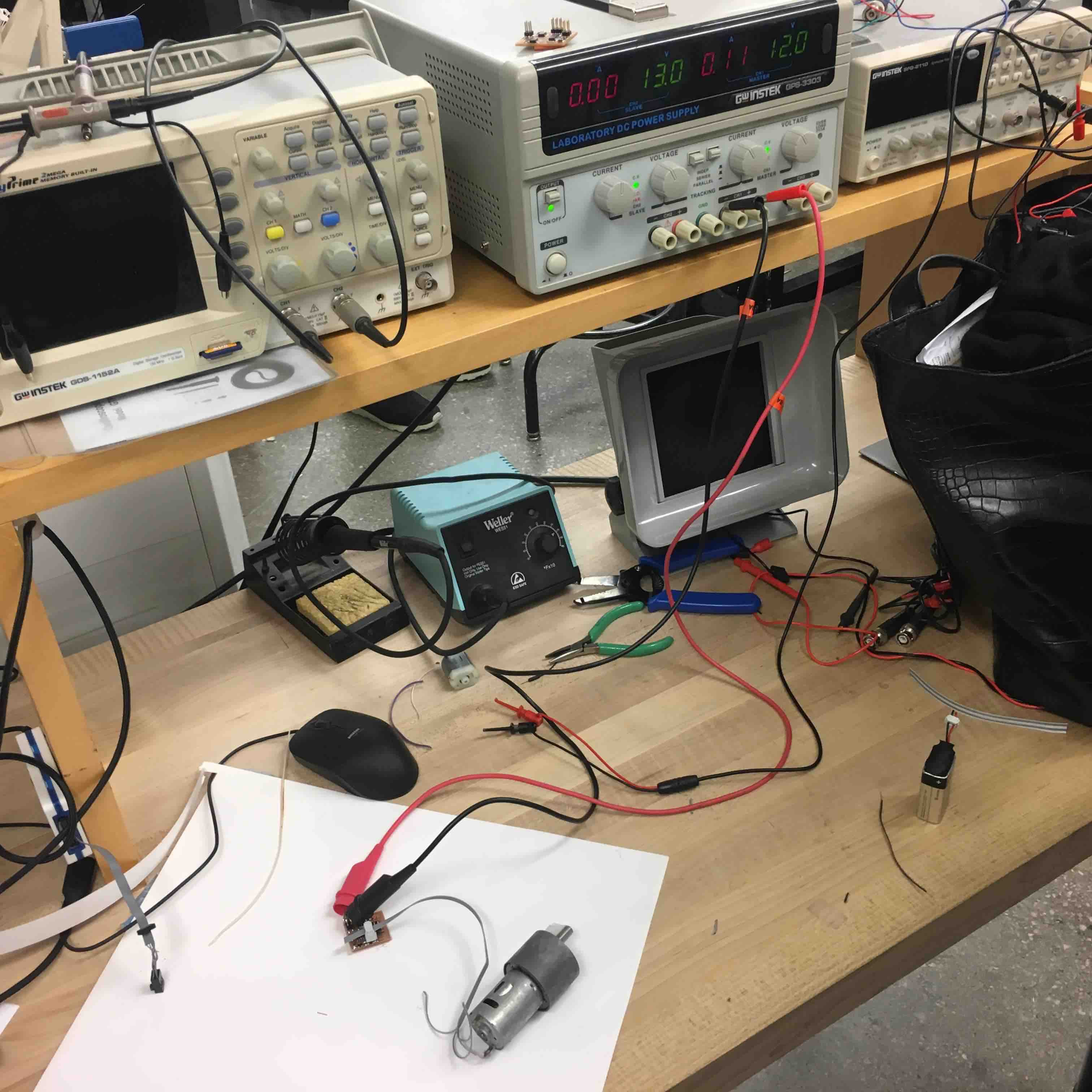
We tried a second DC motor on the board, this one as a gear reduction motor that spun at 5 rpm. For this motor we needed much more power so we used the power supply in the lab.