Week 7: Moulding and Casting

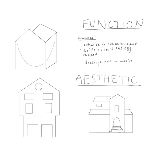
I decided to make a planter for my house after seeing these pots in the shapes of houses. I sketched my current (occasional) home in Cambridge and my home in Colorado. After thinking about the difficulty of creating overhangs in the current house, I decided to model my home in Fusion.
Since I wanted my planter to be taller, I used three pieces of wax vertically to create one model split into thirds.
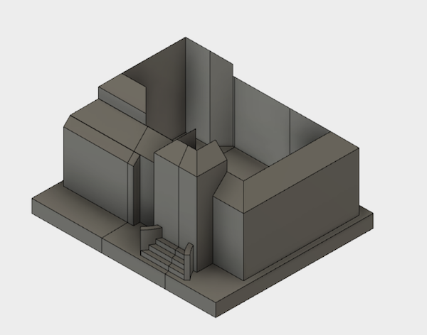
I cut it on the shopbot which was a much better workflow for me. The tops of my roofs kept cracking off (even after changing the tool settings). I was able to immediately chamfer the roof edges a little bit and go back to the CAM software.
I put them all together and carved a door and a window by hand. I also used the heat gun to smooth the inner and front seams.

I built some walls with aluminum foil covered cardboard (next time I would use vinyl because the foil peeled up even though I taped it). The foil made my walls a bit too thin so I needed a support for my mould.

A comparison between the actual house and my potted model:


How to Use the Shopbot with Fusion 360:
1. Inside Fusion, to set up a tool path you must:
-Change the tool to the one you are using - Measure the tool! - tools are measured from the bottom of the tool to the top of the given dimension.
-Change the stock to the size your stock is.
-Make sure you have no sharp edges (add a slight chamfer if possible).
-Calculate the feeds and speeds (be thoughtful of the speed range your machine is)
2.Put your tool into the machine. Be sure to use the correct collet diameter for your tool. Torque your tool into the machine using the torque wrench (77 foot/pounds).
3. Attach your stock to the surface of the shopbot - be sure to mark off a FLAT place in X and Y so that your stock is aligned properly. Confirm that the orientation is what you expect; on the Shopbot y is HORIZONTAL and xis VERTICAL. Hotglue it down making sure that the joint looks "wet" which means there is a firm connection between the two surfaces.
4. Put the middle of the tool above the corner that you have called zero in Fusion. This is really important! Make sure they match - perhaps even turn the model to how you have the stock. Note the x and y coordinates. By clicking on any of the red numbers, you can change the zero officially, so set this place as the new origin.
5. Zero the Shopbot (Cut and then Zero with Plate) in Z. You need to place the plate on the flat surface and clip the black clip to the tool so you're creating a circuit between the two. If your origin is not on the surface of the shobot (i.e. the top of your stock), you must also change the zero to the height of your stocks. Clicking on any of the red numbers, you can change the zero officially again in Z.
6. Warm up the spindle! The key for the spindle must be in the correct position. This will take a while as it is physically warming up. Which means it is a good time to do a sanity check in simulation - is the rate of removal of material realistic (stepdown and stepover)? Are there any collisions? Is the finish the kind of finish you want? Make sure that the tool is actually the right tool and that your feeds, speeds, stepdown and stepover are correct. If satisfied, export the file using "Post Processing" to a .sbp and transfer it to the computer.
7. After warmup, you can cut! Check that the spindle speed on the machine is the same as the one on your screen - it will sometimes reset to the default. You may also need to turn on the spindle which is the blue (middle) botton on the button console. If you're worried about the tool path it is a good idea to look at the first direction the tool will move on the simulation as a sanity check. Hit Start and watch it mill! Spmyace is a "pause stop" and the red button is a "absolute stop" (turns off everything).