Zach Cohen / How to Make (almost) Anything
Final Project Proposal / End Effector for Concrete Extrusion on a Robotic Arm
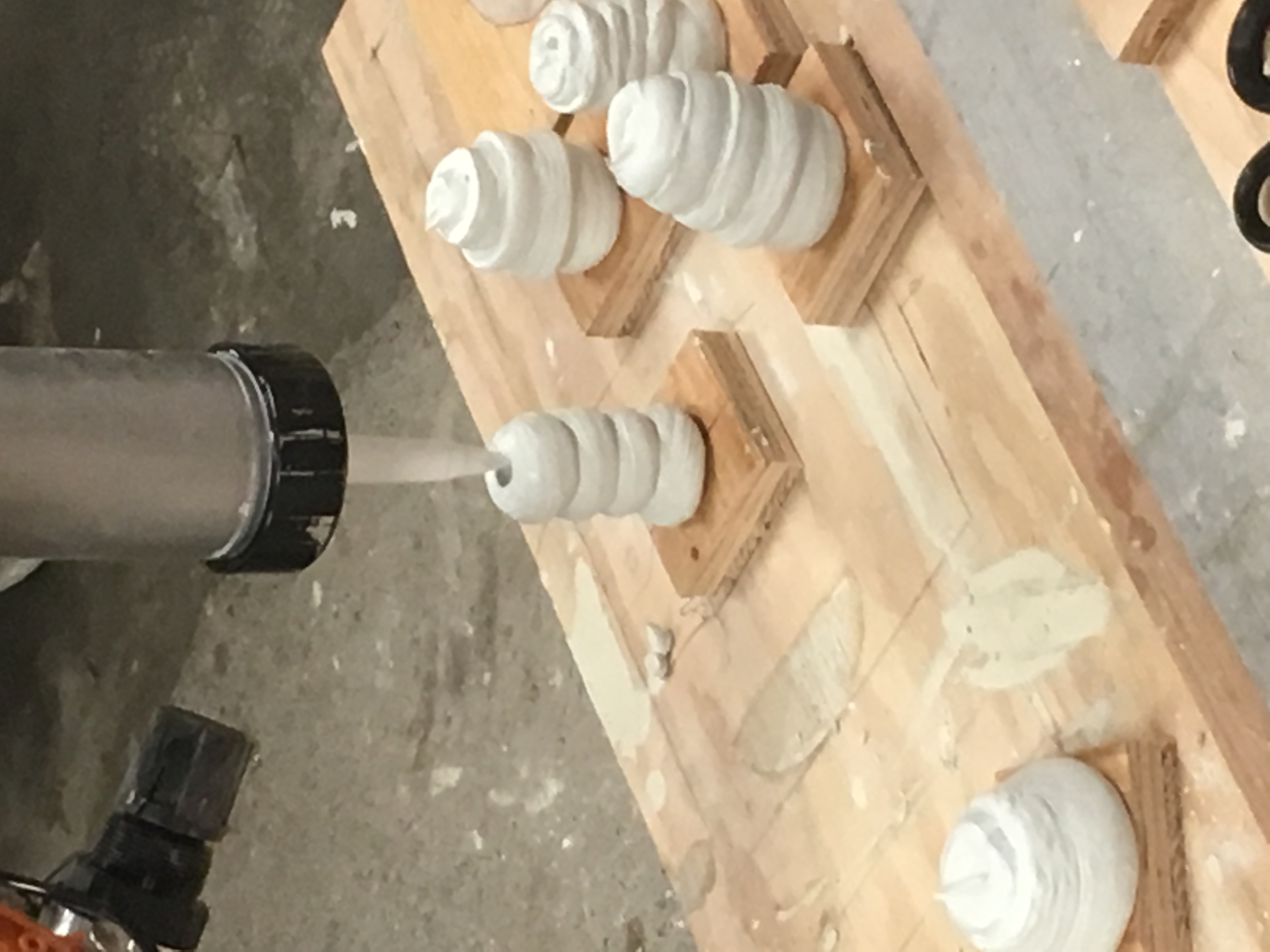
My final project will be the design and fabrication of an end effector for concrete extrusion to be used on a robotic arm. There have been recent developments in concrete 3D printing, by Ronald Rael at UC Berkeley or Behrokh Khoshnevis of Contour Crafting, however these systems inherit the same workflows as their desktop counterparts, i.e. slicing then printing. My 3D printing system, pointillistic time-based deposition(or dripping), does not print in sequential slice but rather in points. As such my extruder will be built to accommodate such pulsation and the formation of concrete "drops."
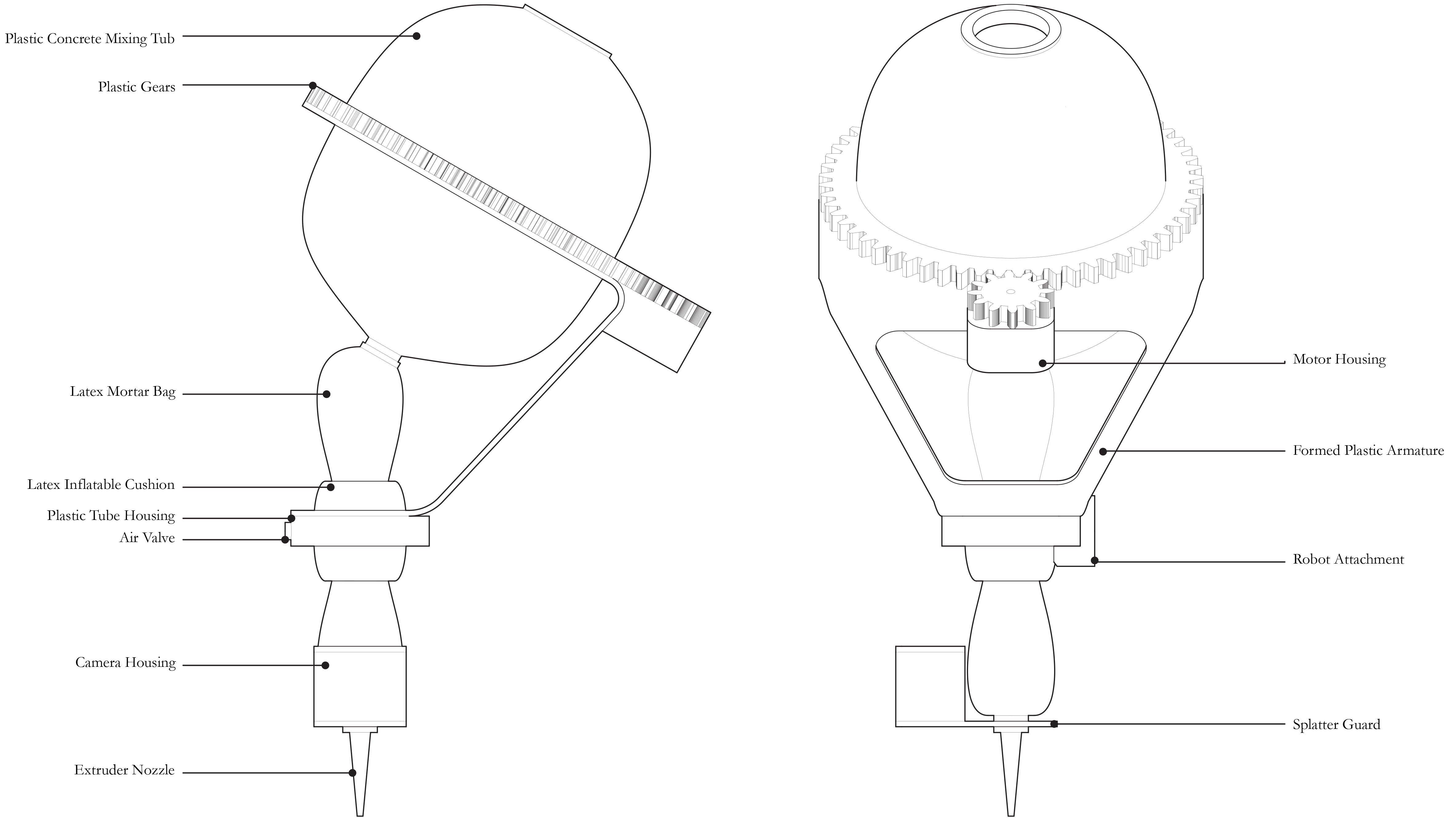
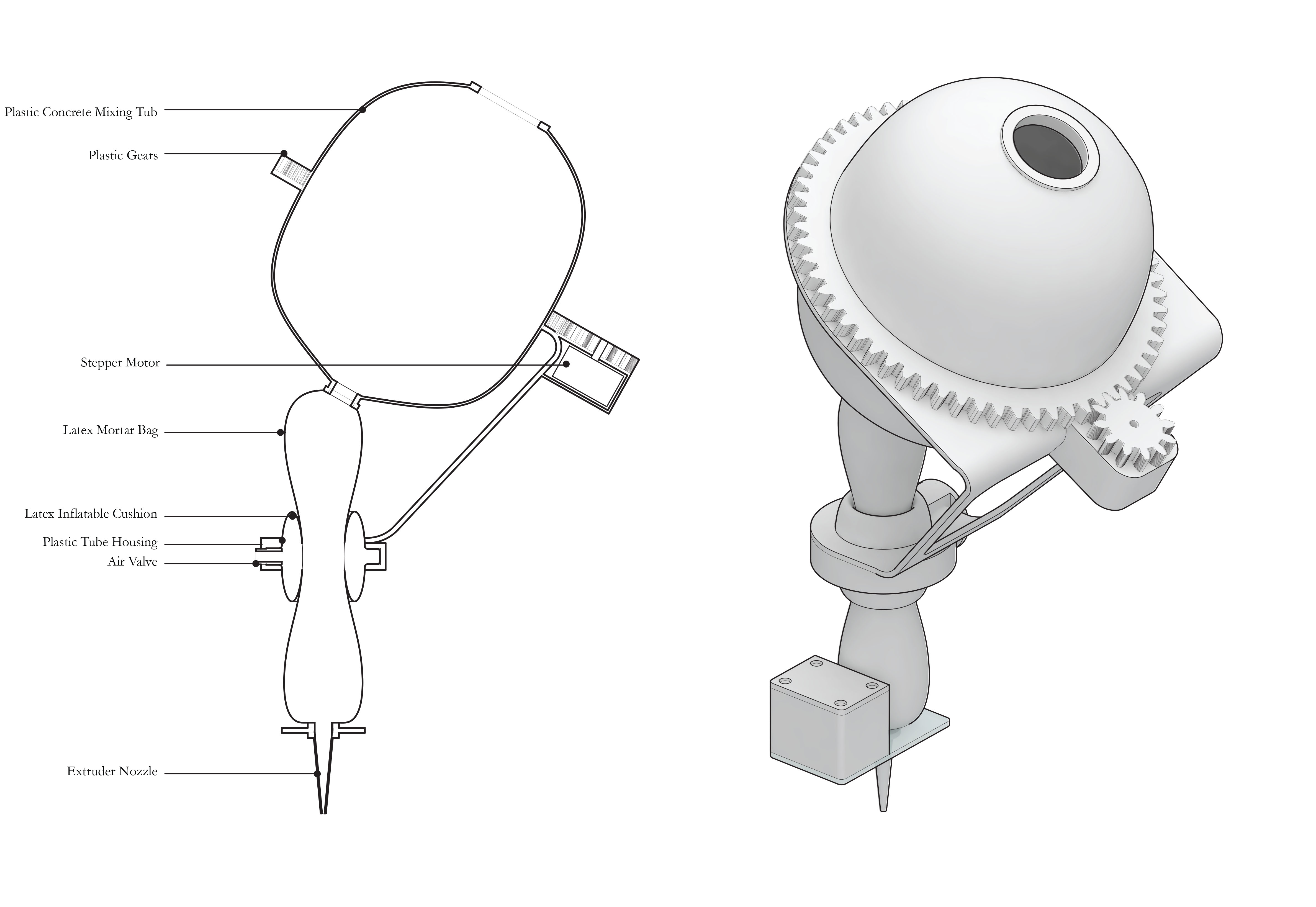
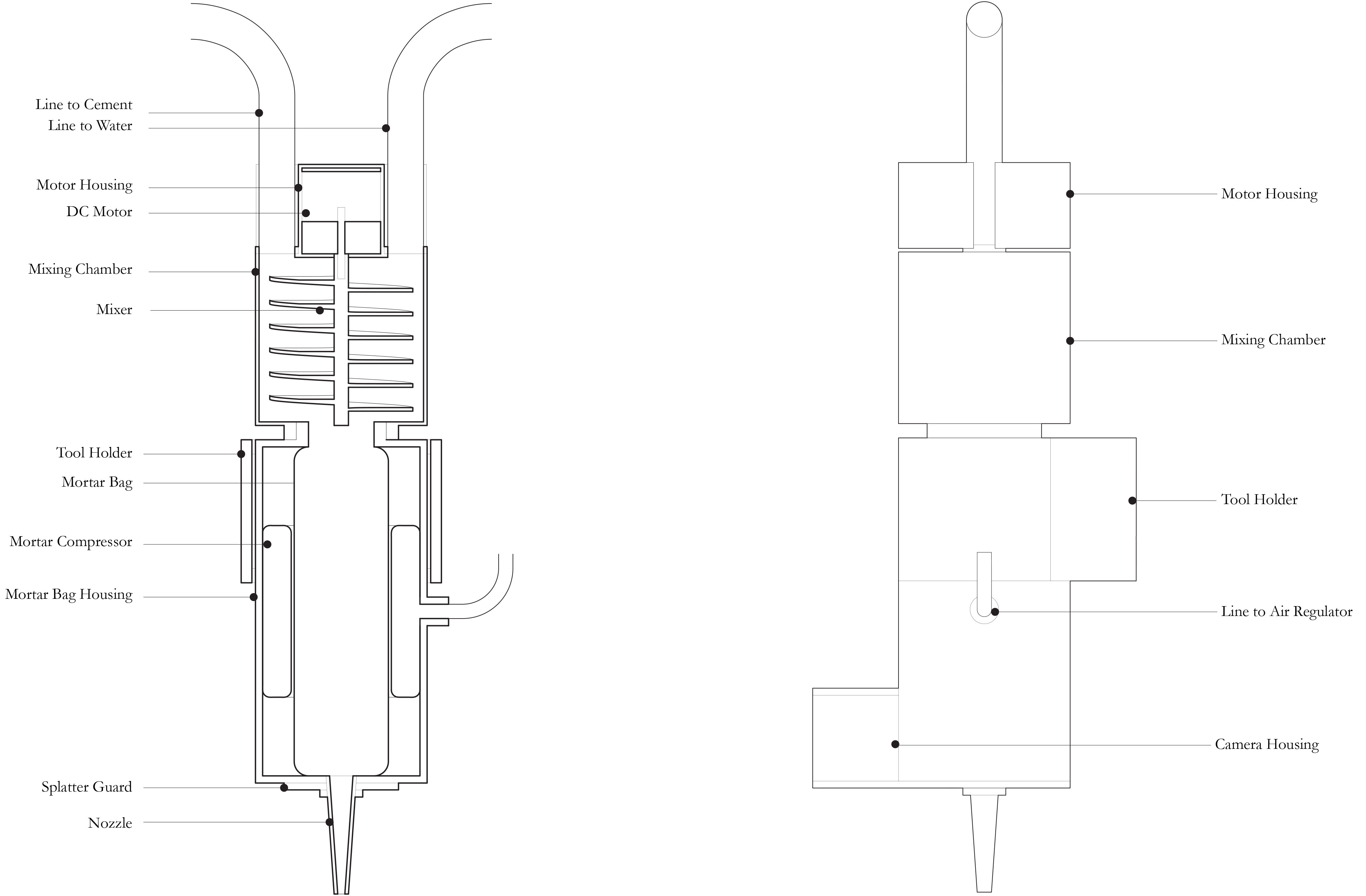
The end effector will be comprised of three parts: the mixer, the extruder, and the nozzle.
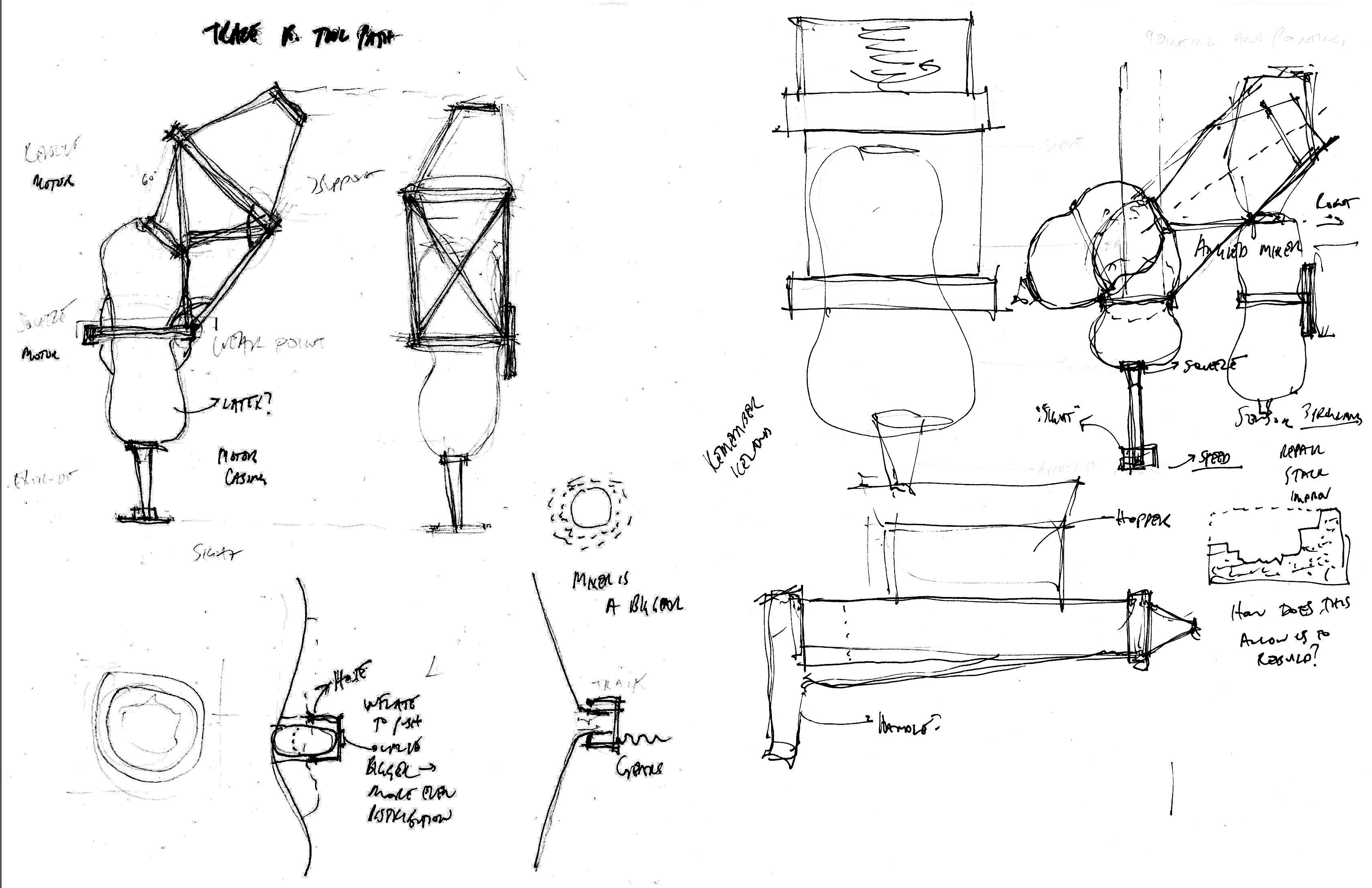
This was the original sketch: The mixer will have two lines feeding it: one for cement and the other for water. The concrete will be mixed and immediately fed into the extruder. The mixer will only mix the amount required for the specific path in the specific job. The extruder will be a grout bag that will be activated by a pneumatic compressor that is fed from the air that flows through the robot. The nozzle will maxmize flow control and be equipped with temperature sensors that can gauge the cure rate feed it back into the tool path generation.
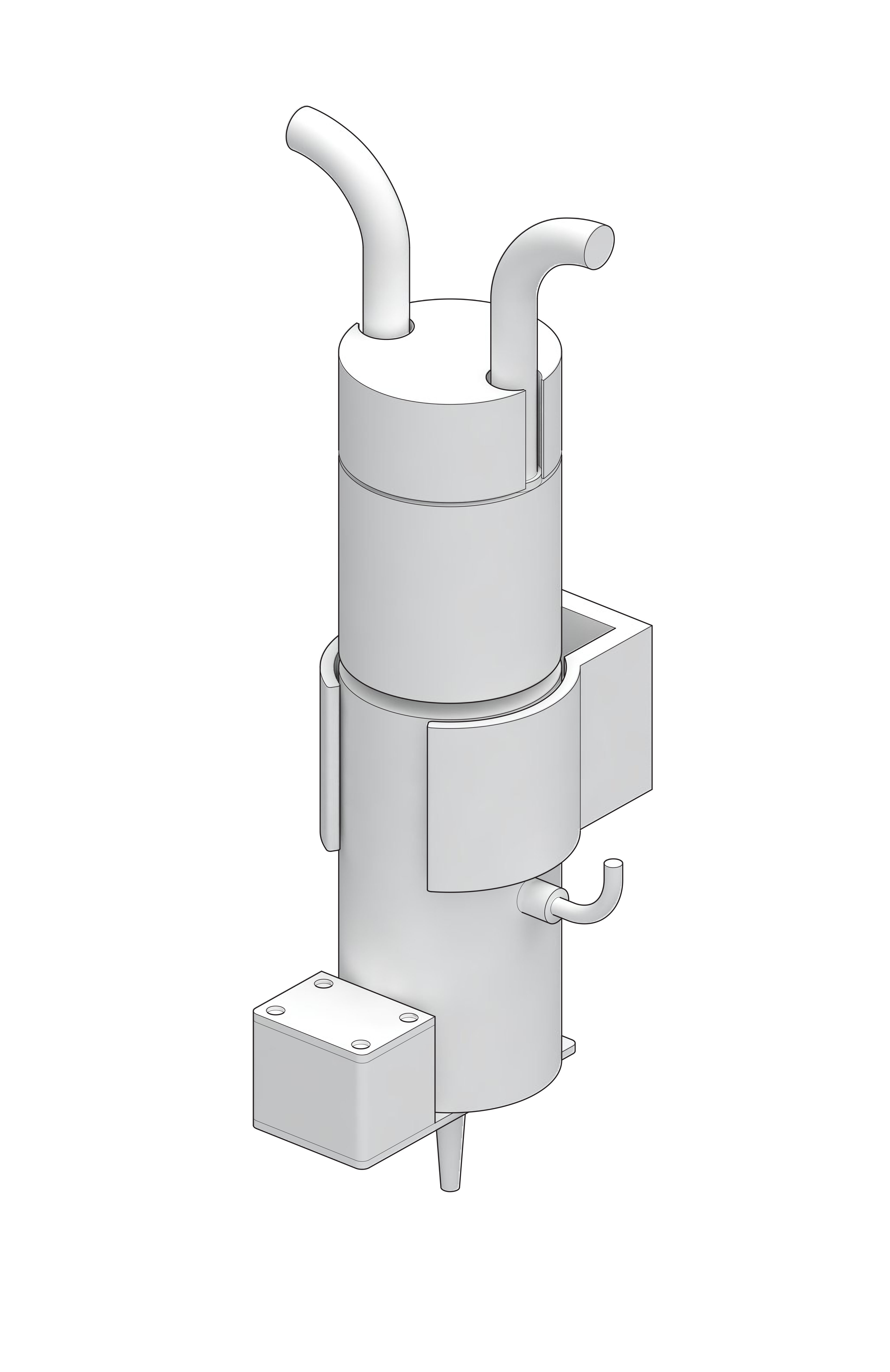
The first sketch did not take into consideration the limited carrying capacity of the robotic arm and therefore was abandoned for a more lightweight, compact design.
This end effector will be used for my thesis research, which is using machined delay to investigate an architectural design approach to digital fabrication.
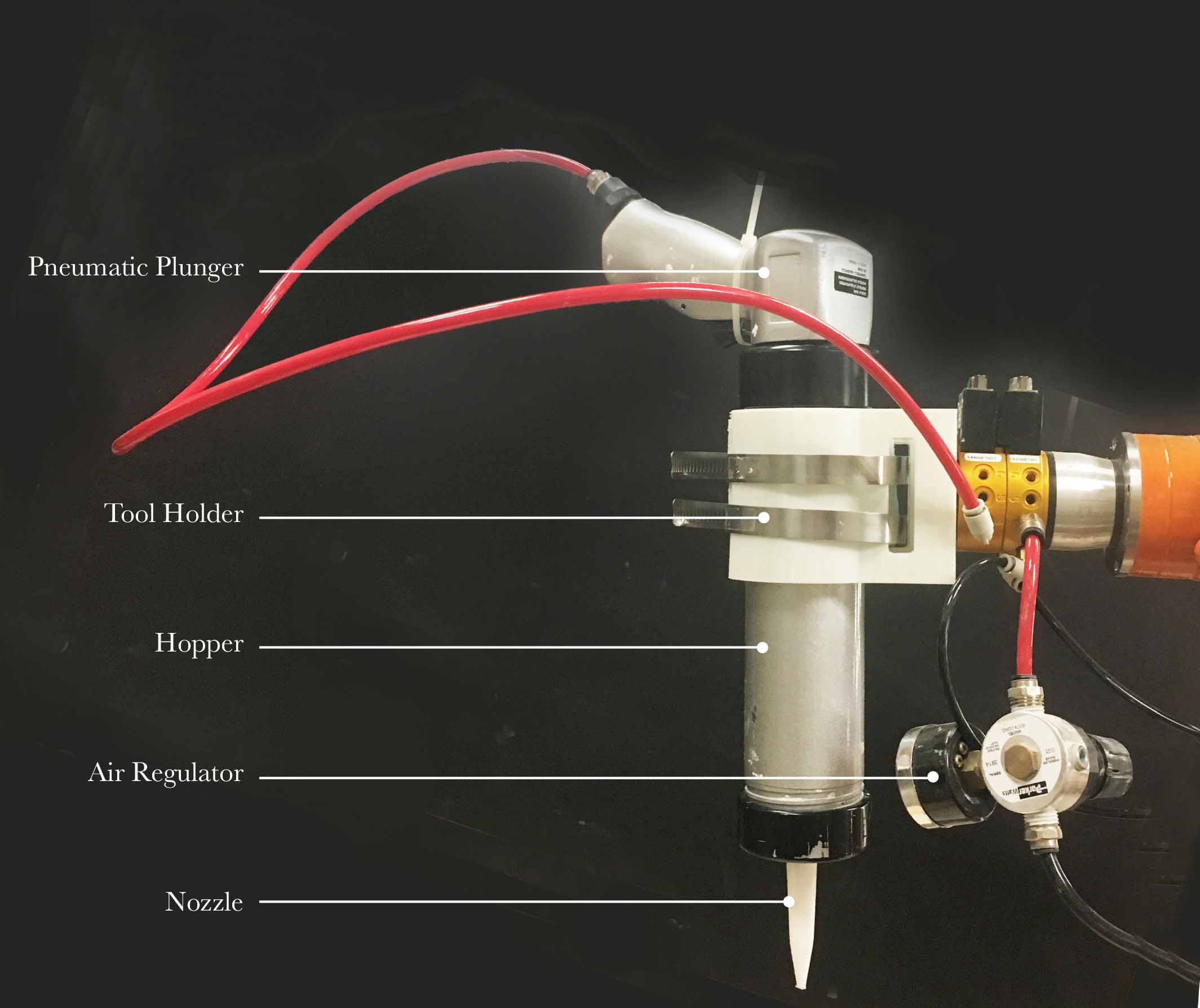
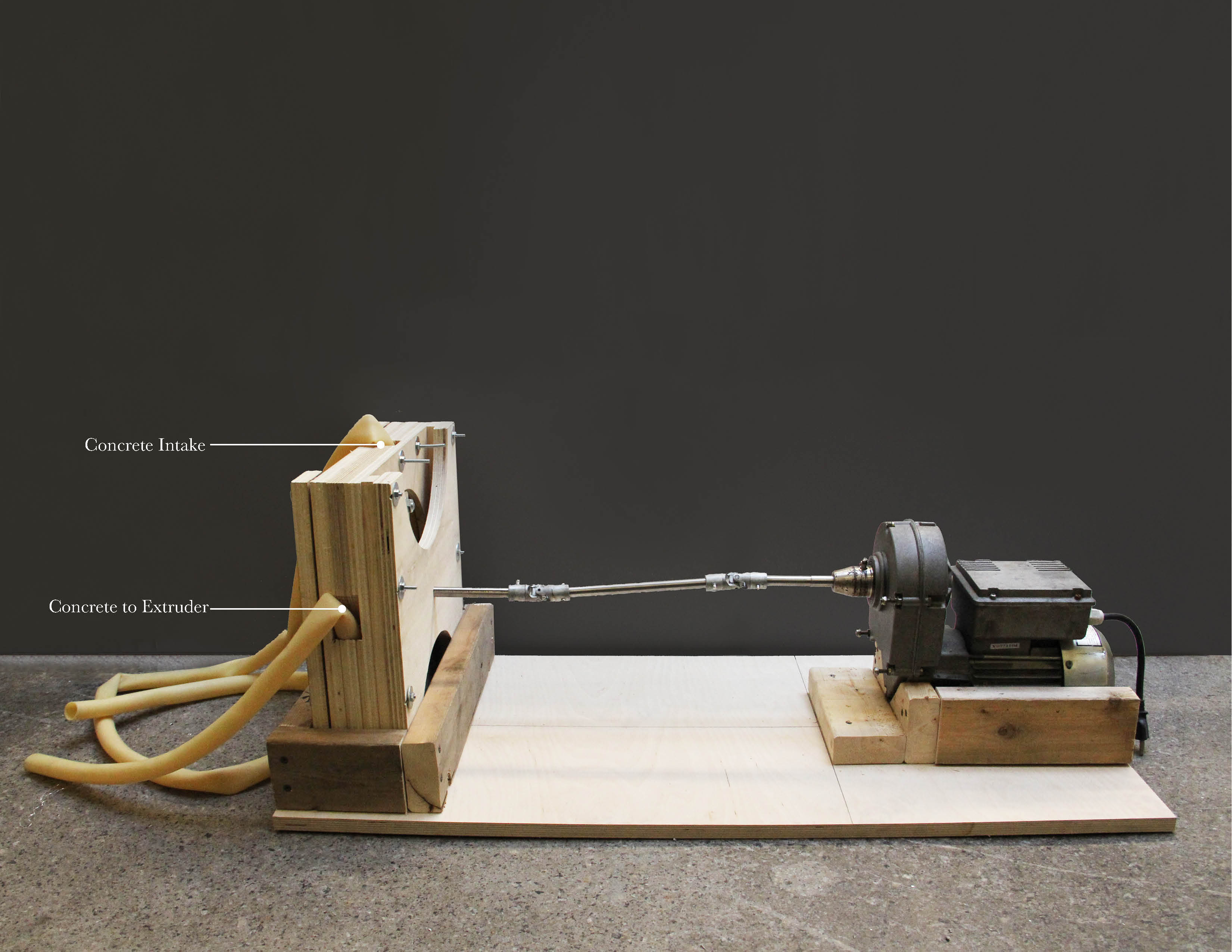
The final design of the extruder is a simple pneumatically actuated piston pump that pushes concrete through the nozzle. The piston cylinder is equipped with a magnet and hall effect sensors so I can track the vertical position of the plunger. The vertical position will indicate the available printing volume. This value will then be communicated to the peristaltic pump and turn it on or off according to how much the designer wishes to extrude.
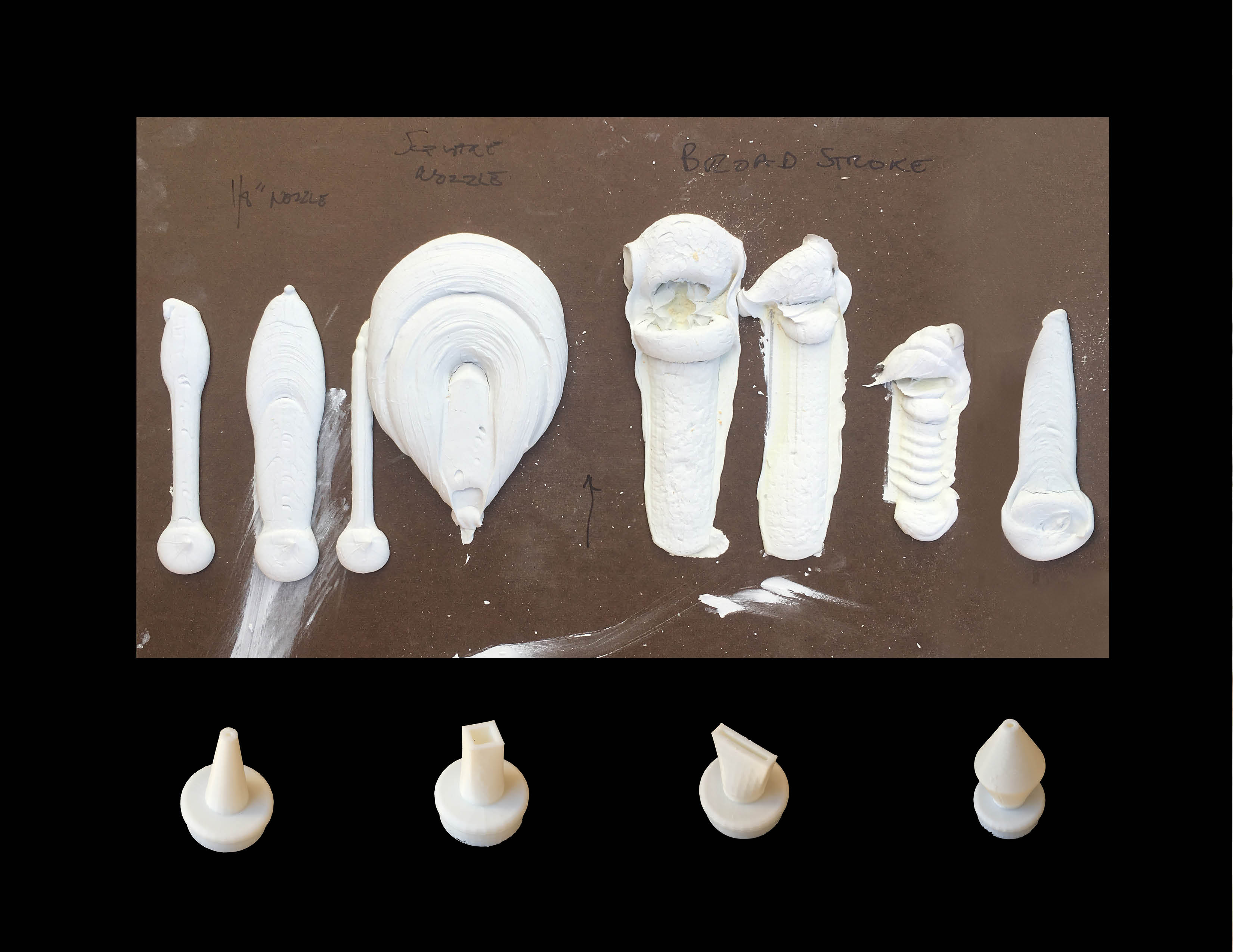
In the 3D printing week, I tested several different nozzle shapes to find the one that works best with my pointillistic time-based deposition system.
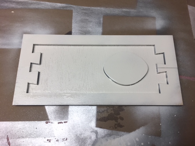
I lasercut and spraypainted a mold for the toolholder gasket and cast it out of silicone.
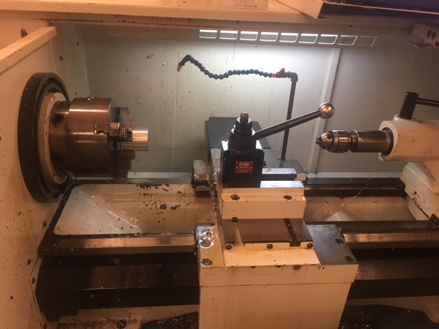
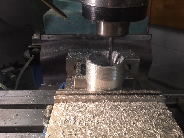
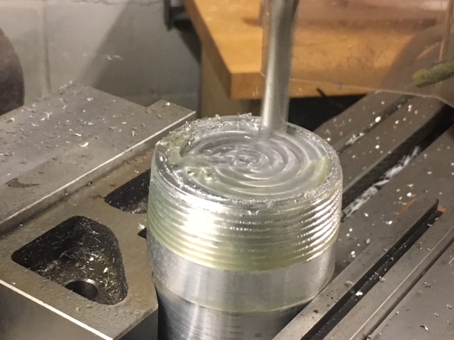
I milled and threaded the endcap and nozzle out of solid aluminum. Most of the machining was done on a CNC lathe, however, the interior of the nozzle was milled using a knee mill.
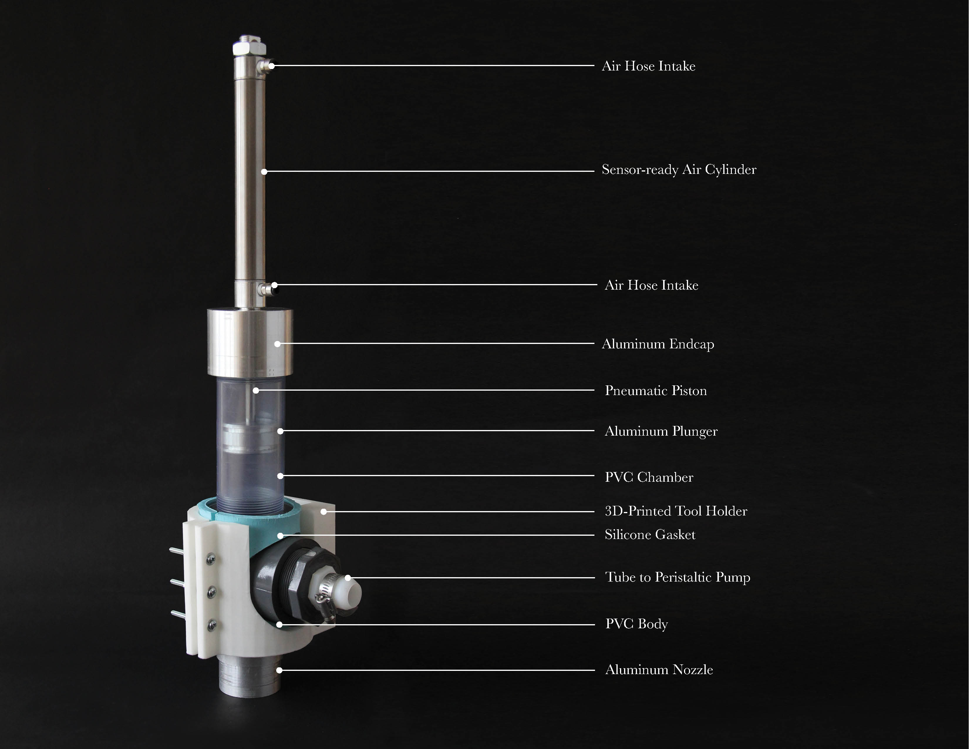
The PVC pipe fitting and pneumatic cylinder were bought as premade components. The cost for all of these components was approximately $85. I fabricated everything else: the endcap and nozzle out of aluminum, the tool holder was 3D-printed in plastic, the gasket was cast out of silicone, the circuitboards were milled, and the sensor housing was formed out of aluminum. The material costs were approximately $40.
In week 9, I got my solid state relay working to turn the motor for my peristaltic pump on and off. In that week, I was simply using a button to pull the input low, however for the final project I had to find another input that could actuate the solid state.
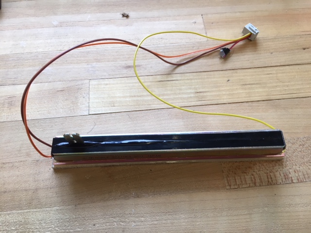
I tested limit switches as well a slide potentiometer to track the vertical position of the plunger and communicate with the pump. However, I ended up settling on two hall effect sensors and a magnetic air cylinder.
.JPG)
I got my hall effect sensor working with my Solid State Relay board. The hall effect sensors will track the depth of the pneumatic piston and turn the peristaltic pump on or off depending on if the extruder head is full.
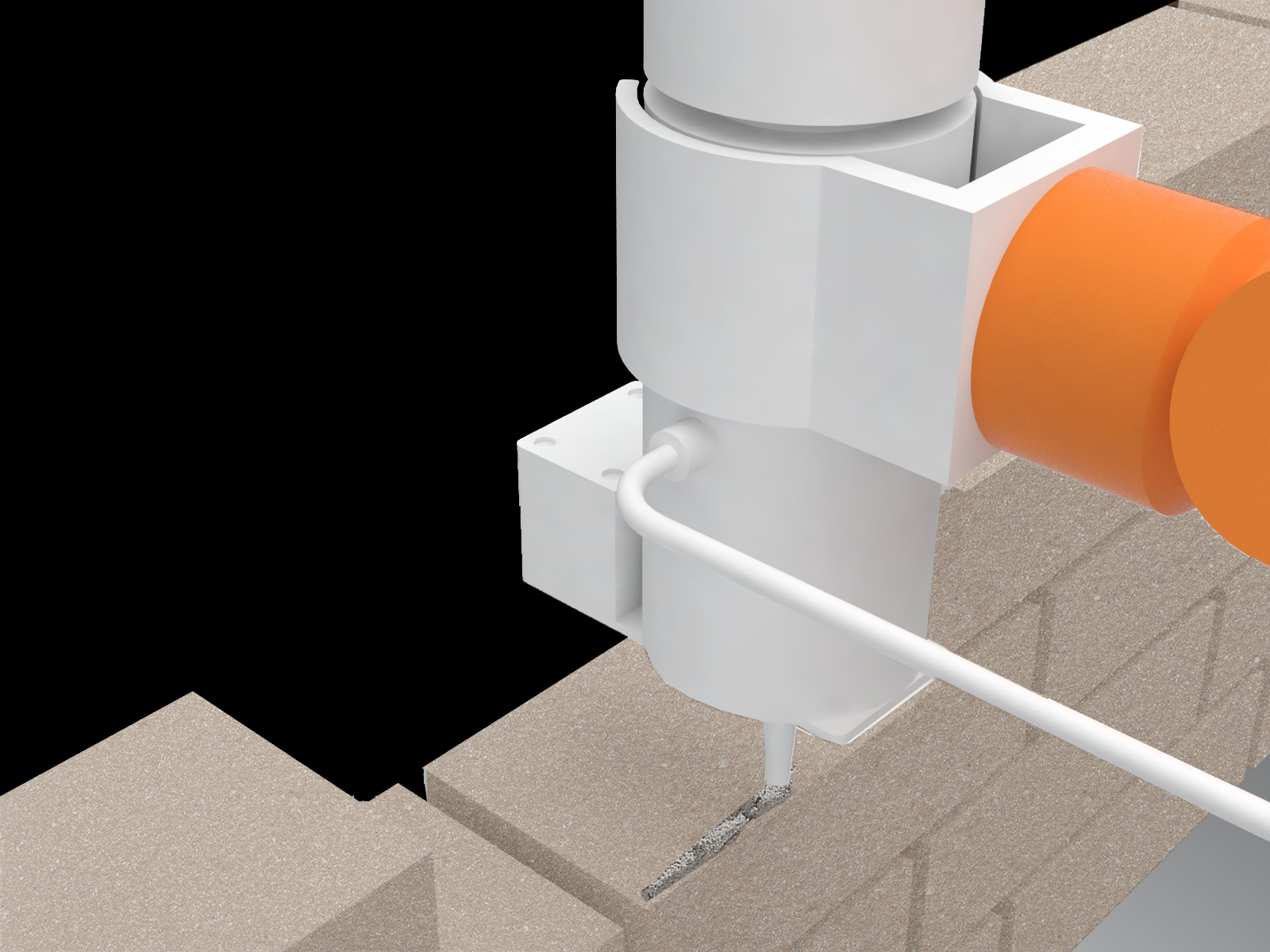
Here is the electromechanical system working altogether, though importantly without material! I tested extrusion separate from the electronics, however the material has to be calibrated further with the machine before a complete test can be carried out.