7.2 programming
The task this week is to program a circuitboard (either the one made a couple of weeks ago, or a new one). Deciding to use this week to try and talk to (and hopefully program) the chip I might use for my final project, I ended up having quite a frustrating time with surrounding problems. As such, no program; though I do have a much better idea of what's happening with the chip, and know what I need to talk to it.
I wanted to use this week as an opportunity to test the chip I'm hoping to use for my final project. This had come at the reccommendation (and kind donation) from Jake, with whom I'd been chatting about my project in the Computer Networks class. The nRF52832 (made by Nordic Semiconductor) is an ultra-low power 2.4 GHz wireless chip, with a 2.4 GHz transceiver and a flash memory. Nordic say it's:
which sounds pretty good for my purposes. Jake also pointed me to the group GitHub, which contains a number of guides on usage and a couple of model PCBs.
Initially, I confused the chip I'd been given (the nRF52832, for which there are a number of example circuits both online, and in the GitHub), with the nRF52840, which is significantly less well documented. They're both variants on the nRF52 family, and do similar things, but initially trying to design for the nRF52840 required a lot of background reading, documented here. As a PCB with high frequency GPIO and TX/RX (clocking at almost that of the ATTiny), Nordic lists a number of detailed reccommendations for the nRF52.
I've got a background in electronic engineering, but it's amazing how quickly you forget things (especially when you only learned them 2 weeks before an exam in the first place), and I've been excited to properly revisit RF electronics.
For a complex input impedance and output impedance , maximum power transfer is obtained when:
and minimum reflection is obtained when:
When resistance is purely real, the load impedance and its complex conjugate are equal, and power transfer maximisation is equivalent to reflection minimisation. In their guidelines, Nordic provide an example schematic of impedance matching to a PCB antenna.

Nordic also reccommend the use of a Balun (a component I'd not come across before) which converts between a balanced and un-balanced signal. I decided to test out their matching circuit before the balun, but might give it a try in the future.
The nRF52832 chip I'd been given was the MDBT42Q package. This is different to the package detailed on the CBA Github, but is the package used to make the Adafruit feather, which is an integrated nRF52 board. Adafruit have the Eagle file library on their GitHub. At this point (Monday), I was becoming a bit concerned about time so I (foolishly) decided to try and cut the Adafruit board on the milling machine. T
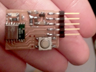
his would have been a nightmare to solder (and, mid-milling, I realised I didn't have a number of the components on the partlist), so it was a relief when, halfway through, Jake came into the workshop and said they had some spares of the BC832 package, which are documented here on the CBA GitHub. I used the png files from that to create a new board, and soldered the components; the BC832 has pads on the underside; in order to solder these, a bead of solder is added to both the board and the pin on the chip underside. After the whole chip is soldered, a hot air gun on the top of the chip should bridge the connection between the two.
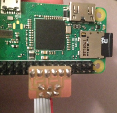
It's not straightforward to talk to the chip -- need to talk to it using the SWD pins (serial debugger), that rely on either access to a Segger Jlink (which are $$$, and nobody seemed to have), or a clever hack using a Raspberry Pi Zero and a technique called 'bit banging' to chat to the nRF52 over the SWD IO. This requires another smaller board to attach the pi to the chip, and a separate cable.
Unfortunately, I couldn't make the ethernet-ssh protocol work. An original problem was that the micro USB cable I'd been using was just for power, and was not allowing the pi to talk to the computer. The USB type needed is an OTG (on-the-go), which allows a back-and-forth between the pi and the computer. This, however, didn't fully work; I suspect that the pi wasn't actually being discovered -- and the network wouldn't let me authenticate.
At home, we had an original Raspberry pi configured to run Piratebox, a DIY offline wireless network which I'd used before to discover and talk to Raspberry Pis where I'd had this problem. However, it was on getting home that I realised the only functional micro USB we had was the one in my bag (our other one was broken), making it impossible to have the PirateBox Pi and the Pi Zero run simultaneously.
It being late, I resolved to solve this tomorrow (and hopefully talk to the chip!); it's frustrating to have what should be a simple process throw up so many bugs, but I've also made (some) progress.
The nrf52
I wanted to use this week as an opportunity to test the chip I'm hoping to use for my final project. This had come at the reccommendation (and kind donation) from Jake, with whom I'd been chatting about my project in the Computer Networks class. The nRF52832 (made by Nordic Semiconductor) is an ultra-low power 2.4 GHz wireless chip, with a 2.4 GHz transceiver and a flash memory. Nordic say it's:
the ultimate SoC for any short range wireless personal area network or IPv6-enabled automation application.
which sounds pretty good for my purposes. Jake also pointed me to the group GitHub, which contains a number of guides on usage and a couple of model PCBs.
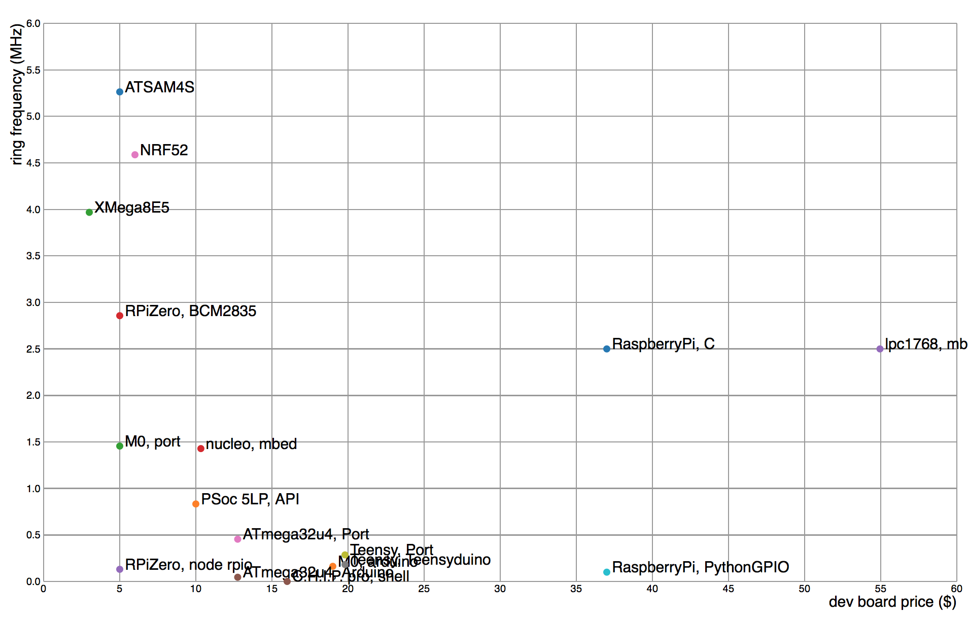
Initially, I confused the chip I'd been given (the nRF52832, for which there are a number of example circuits both online, and in the GitHub), with the nRF52840, which is significantly less well documented. They're both variants on the nRF52 family, and do similar things, but initially trying to design for the nRF52840 required a lot of background reading, documented here. As a PCB with high frequency GPIO and TX/RX (clocking at almost that of the ATTiny), Nordic lists a number of detailed reccommendations for the nRF52.
I've got a background in electronic engineering, but it's amazing how quickly you forget things (especially when you only learned them 2 weeks before an exam in the first place), and I've been excited to properly revisit RF electronics.
Impedance Matching
One of the key components of the nRF52 chip is the potential to communicate with other chips via radio-frequency signals (in the wifi range). This gives it a lot of exciting possibilities for networking. In high frequency circuits, the wavelength of the signal becomes comparable with the length of the chip, introducing a number of interesting effects due to phase differences. In order to get a sufficient signal strength out of an antenna, the circuit needs to 'impedance match' this component. Impedance matching maximises power transfer and minimises reflected signal due to phase differences. The nrf51 and 52 are largely the same, with impedance matching being the greatest key difference.For a complex input impedance and output impedance , maximum power transfer is obtained when:
and minimum reflection is obtained when:
When resistance is purely real, the load impedance and its complex conjugate are equal, and power transfer maximisation is equivalent to reflection minimisation. In their guidelines, Nordic provide an example schematic of impedance matching to a PCB antenna.
Nordic also reccommend the use of a Balun (a component I'd not come across before) which converts between a balanced and un-balanced signal. I decided to test out their matching circuit before the balun, but might give it a try in the future.
timing
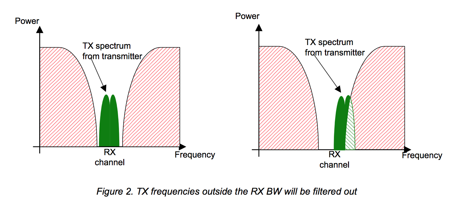
Nordic provide a set of guidelines for designing crystal oscillator timing circuits. On an nRF52, an external 32 MHz crystal is required for clocking the circuit, and an external 32 kHz crystal is also optional for keeping time on the order of hours, days and months. Incoming RF signals must fall within the Rx channel range -- any signal falling outside this range will be filtered out as noise. (the 'channel' in this case is 2.403GHz, the 802.11b, n and g wifi standard range).
decoupling
DEC pins give decoupling capacitors: used to decouple power sources from the chip. Smooths out the voltage. Compensates for delays in the power supply-smooths outGround planes
The spec states that ground plane(s) should be as large and as solid as possible. Though Nordic suggests that a typical design might have 2 ground planes, for a simple board one should be sufficient, provided bypass capacitors between VCC and GND are included.Eagle schematic
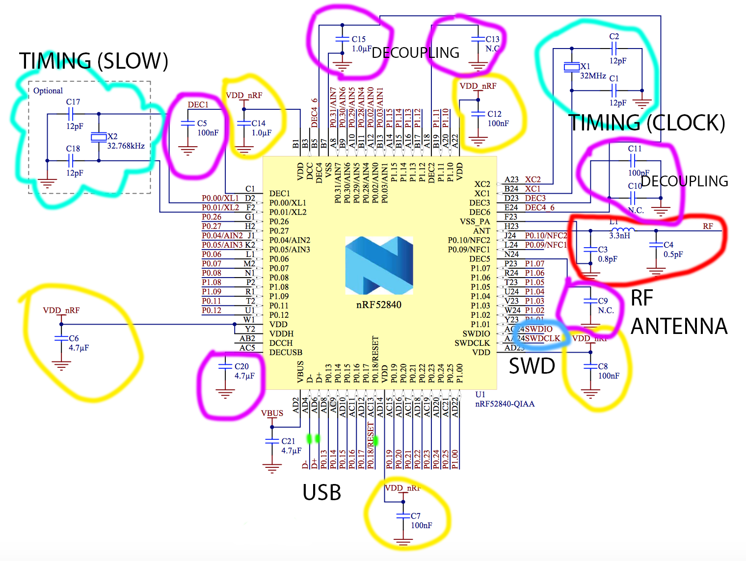
It was partway through making the Eagle schematic for the NRF52840 (labelled diagram below), when I went to my office to get the chip, discovering it was actually the considerably more well-documented NRF52832. This was frustrating, but it was nice to know I wouldn't have to start from scratch. The diagram below shows the parts of the surrounding circuit dedicated to timing (turquoise), decoupling (pink), USB (green), RF signal (red), and power supply (yellow). The NRF52832 and NRF52840 aren't that different, however, the NRF52840 is the only package that has USB interface support: the NRF52832 requires a different using a serial debugger (more on that later).
The nRF52832 chip I'd been given was the MDBT42Q package. This is different to the package detailed on the CBA Github, but is the package used to make the Adafruit feather, which is an integrated nRF52 board. Adafruit have the Eagle file library on their GitHub. At this point (Monday), I was becoming a bit concerned about time so I (foolishly) decided to try and cut the Adafruit board on the milling machine. T
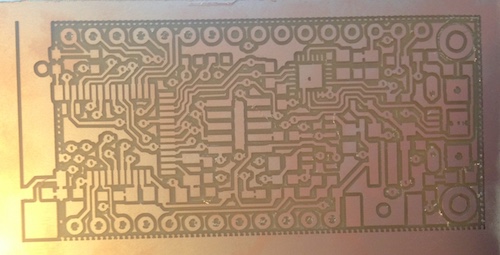
his would have been a nightmare to solder (and, mid-milling, I realised I didn't have a number of the components on the partlist), so it was a relief when, halfway through, Jake came into the workshop and said they had some spares of the BC832 package, which are documented here on the CBA GitHub. I used the png files from that to create a new board, and soldered the components; the BC832 has pads on the underside; in order to solder these, a bead of solder is added to both the board and the pin on the chip underside. After the whole chip is soldered, a hot air gun on the top of the chip should bridge the connection between the two.
programming
It's not straightforward to talk to the chip -- need to talk to it using the SWD pins (serial debugger), that rely on either access to a Segger Jlink (which are $$$, and nobody seemed to have), or a clever hack using a Raspberry Pi Zero and a technique called 'bit banging' to chat to the nRF52 over the SWD IO. This requires another smaller board to attach the pi to the chip, and a separate cable.
Raspberry Pi hell
Ironically, the part where I came unstuck was trying to talk to the Raspberry Pi Zero. I didn't have a mini-HDMI adapter handy to plug into monitor, so I needed to SSH. I discovered online that theoretically, you could set the micro-USB up as a USB ethernet, and talk to the pi zero through that. This would be useful, as discovering the pi's IP address without having a monitor attached is really hard over public WiFi -- you need to configure the pi to login to the network (this is ok), but then identify the ip address among the potential tens or even hundreds of people on the same network.
Unfortunately, I couldn't make the ethernet-ssh protocol work. An original problem was that the micro USB cable I'd been using was just for power, and was not allowing the pi to talk to the computer. The USB type needed is an OTG (on-the-go), which allows a back-and-forth between the pi and the computer. This, however, didn't fully work; I suspect that the pi wasn't actually being discovered -- and the network wouldn't let me authenticate.
At home, we had an original Raspberry pi configured to run Piratebox, a DIY offline wireless network which I'd used before to discover and talk to Raspberry Pis where I'd had this problem. However, it was on getting home that I realised the only functional micro USB we had was the one in my bag (our other one was broken), making it impossible to have the PirateBox Pi and the Pi Zero run simultaneously.
It being late, I resolved to solve this tomorrow (and hopefully talk to the chip!); it's frustrating to have what should be a simple process throw up so many bugs, but I've also made (some) progress.