9.2 another board; adding outputs
9.3 same thing, different chip
This week, I wanted to finish up talking to the nRF52, and to use it to drive a couple of servos. At the start of the week, I'd planned to also use this week to test out a basic chassis design and make a little robot that moved around. This, predictably, was consumed by lots of unforseen problems, however now that the nRF52 is talking, I hope to make a working prototype this week.
Instead, I used a pi zero I'd configured a while ago, and pinged it over a local network using
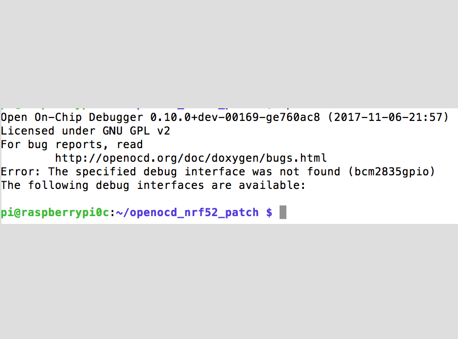
This built fine on the pi, but when it came to configuring the pi as a J-Link, OpenOCD couldn't seem to list the GPIO as an output. By this point, I'd had a conversation with Oren from Human Dynamics, who turned out to have a spare (knock-off) J-Link lying around from his work with the nRF51 chips. Whilst I'm still interested in getting the bit-banging protocol to work, I wanted to get the nRF52 working this week, and debugging OpenOCD could take a while.
programming
Configuring the pi zero
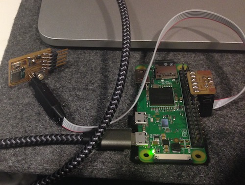
We left the communication with the nrf52 on a cliffhanger 2 weeks ago, due to a failure to talk to (and thus configure as a J link) the raspberry pi zero. Disappointingly, I couldn't manage to get the appealingly simple and straightforward USB ethernet protocol described here.Instead, I used a pi zero I'd configured a while ago, and pinged it over a local network using
ping raspberrypi.local to determine the IP address, and then ssh pi@xx.xx.xx.xx to ssh into the pi. To get a 'local wifi network', I used a pi 3 configured with PirateBox, though phone tethering also works. Next, following Sam Calisch's general Pi-Zero-JLink instructions, I installed OpenOCD, as per the instructions here. This built fine on the pi, but when it came to configuring the pi as a J-Link, OpenOCD couldn't seem to list the GPIO as an output. By this point, I'd had a conversation with Oren from Human Dynamics, who turned out to have a spare (knock-off) J-Link lying around from his work with the nRF51 chips. Whilst I'm still interested in getting the bit-banging protocol to work, I wanted to get the nRF52 working this week, and debugging OpenOCD could take a while.
setting up the JLink
Initilly, I had assumed that the J-Link would just plug in without needing to do very much. This might have been true, had I found the J-Link instructions on Sam's site (which were pretty straightforward). Instead, through a somewhat circuitous root through the SEGGER software, stackOverflow and AVRfreaks (a really useful resource for talking to chips), I found this guide here to setting up JTAG drivers for OSx. The tutorial needed to edit driver FTDIUSBSerialDriver.kext. It turns out on OSx Sierra that this doesn't install, and instead has been replaced with an Apple FTDI driver: AppleUSBFTDI.kext.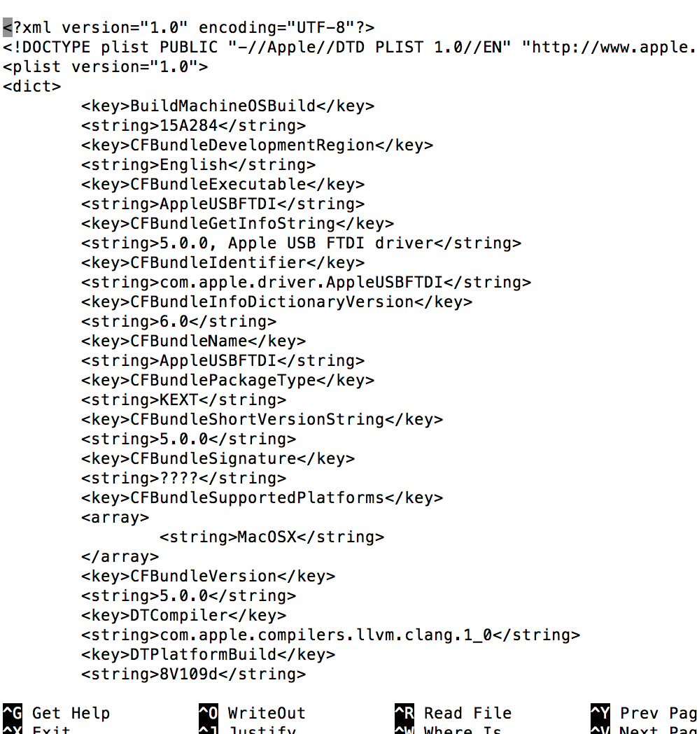
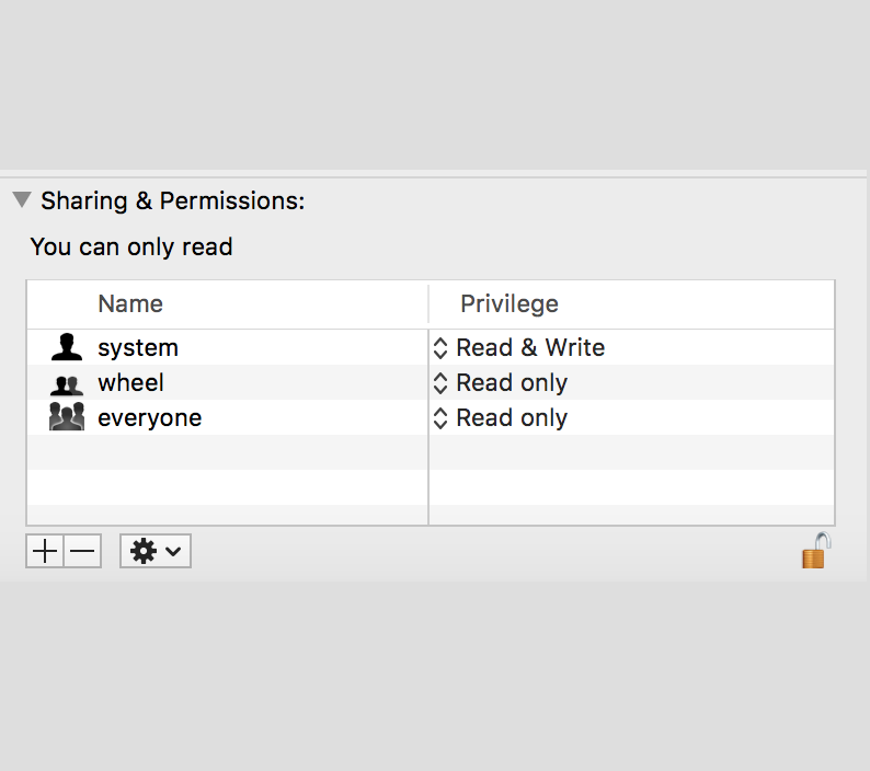
As per the instructions, I tried to edit this file to include J-Link drivers. However, OSx prevents you from editing the text of this driver (even using sudo), as it's an 'apple' driver, not an external one. At this point, I asked Oren for some software advice. He said that he'd worked with SEGGER's J-Link tools software. I downloaded Ozone -- SEGGER's J-Link debugger, and plugged everything in. This started well (it recognised the J-Link), but failed to recognise any nRF52 chip on the other end.
At this point, it was (luckily) pointed out to me by Jake that a key reason the J-Link might not recognise my board was that the BC832 was soldered on the wrong way round. Given that this board was also using a SWD header that didn't match the J-Link connectors I was now using, I decided to mill the new board and test the (correctly-oriented) nRF52 on that instead.
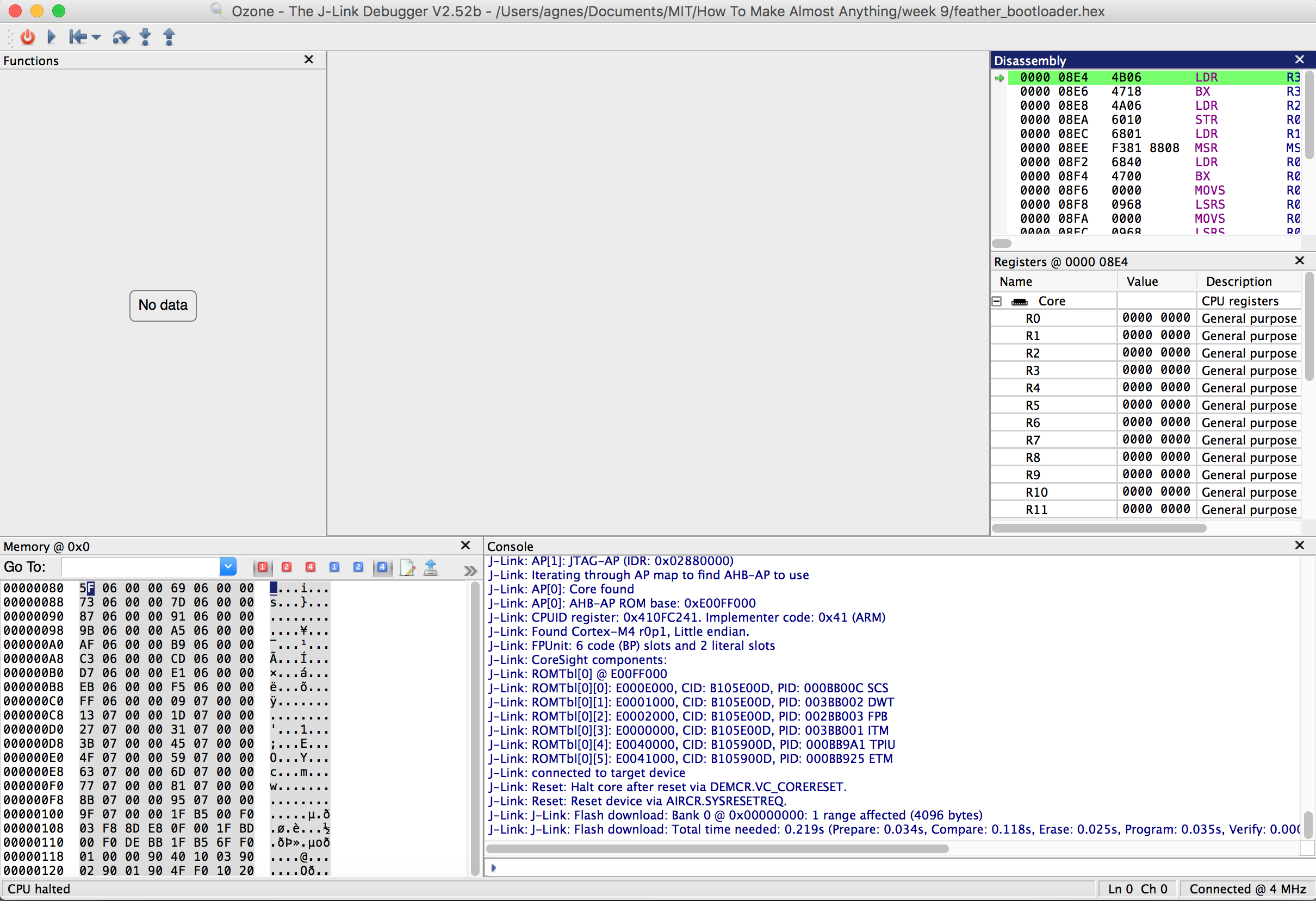
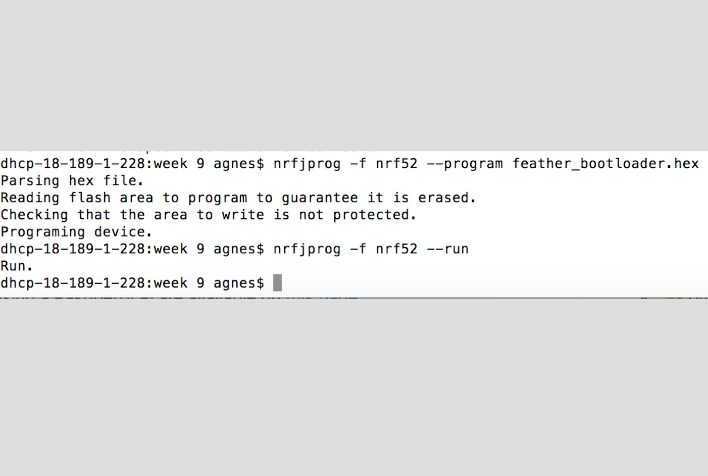
~~some hours later~~ This time, Ozone read my board -- and quite possibly wrote to it -- but I found the interface extremely confusing, and, in trying to upload sketches to the board I was really unsure if anything was running. At this point, I was looking back at Sam's site for a clue to what might be going on with the chip, and saw that he reccommended using the nrfjprog command line tools for Nordic that communicate directly with the nRF52 via the JLink. I flashed the program feather_bootloader.hex: this was successful (and clear), and I was pretty confident that things were working.
The next step was to run a program on the chip: for this, I used the Arduino IDE (for safety and familiarity). In order to do this, the Arduino needs to be able to talk to the nRF52. This is done with a library downloaded here. The steps to installing the nRF52 are to:
- Start Arduino IDE
- Go to Preferences
- Add
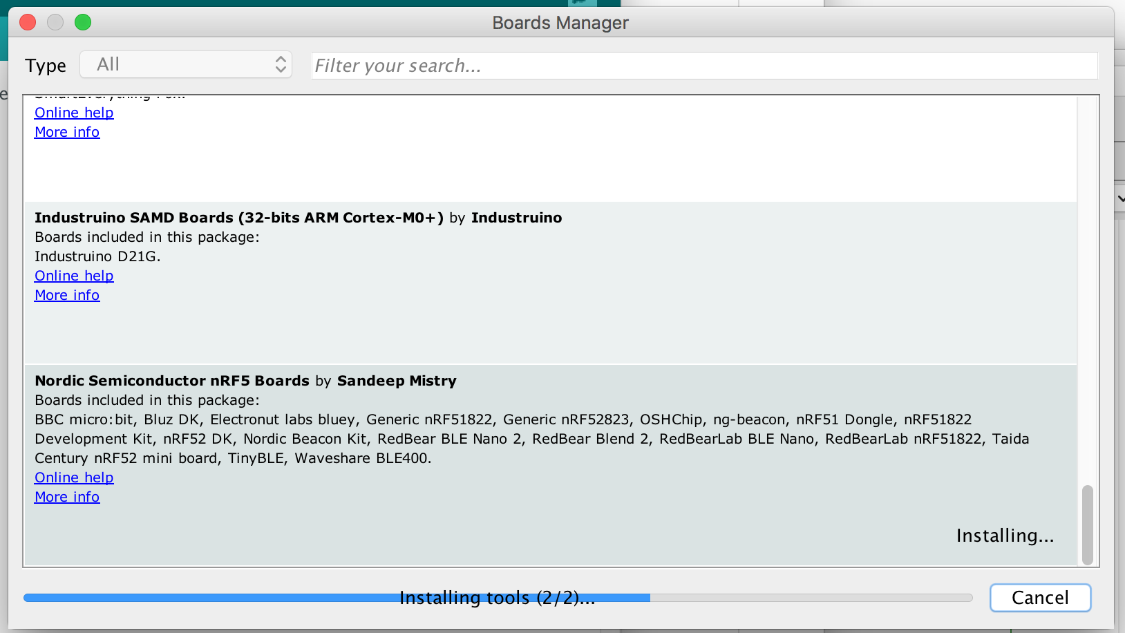
https://sandeepmistry.github.io/arduino-nRF5/package_nRF5_boards_index.jsonas an "Additional Board Manager URL" - Open the Boards Manager from the Tools -> Board menu and install "Nordic Semiconductor nRF5 Boards"
- Select 'Generic nRF52' from the Tools -> Board menu
- Select 'J-Link' from the Tools -> Programmer menu
The first time I tried to compile a sketch to the chip, it returned a
fatal error: MSpanList_Insert error. This was resolved when I updated the Arduino IDE, and then
In hindsight, I'm fairly sure Ozone worked fine: just confusingly, and it might be a more effective way to compile code onto the chip (when compared with Arduino).
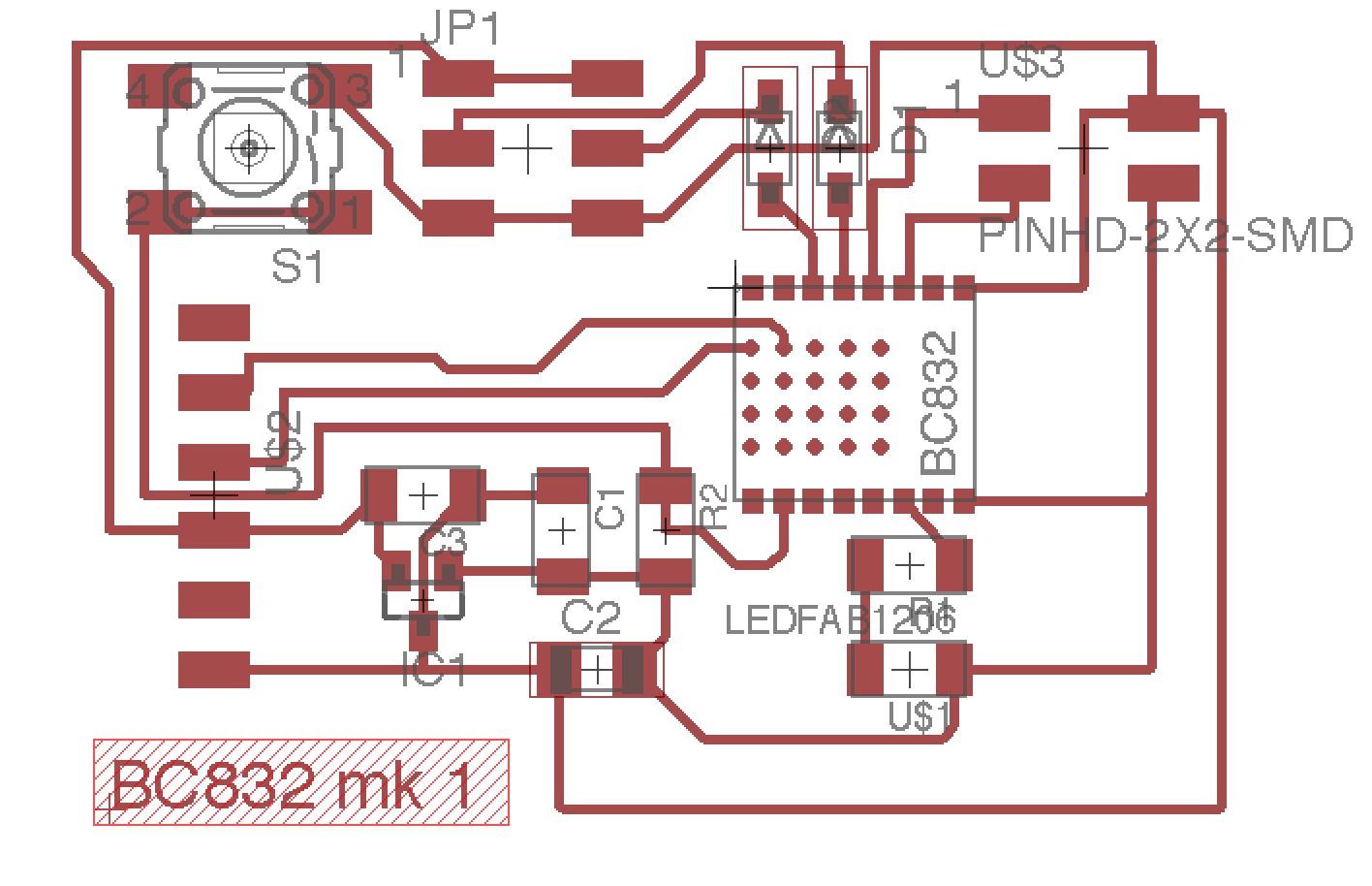
Designing the board
For the setup of the first nRF52 board, I'd used a png from Sam's repo, which gave the simplest configuration needed to run the bootloader onto the chip. In order to generate outputs from the board, I needed to addProblems with Eagle traces
Nordic disribute Eagle lbrs for their boards, including the BC832. On loading the part, the 'board' layout matched the datasheet perfectly -- however, the symbolic schematic layout did not align with the Eagle grid. The way Eagle schematic connects components means that, in order for 2 parts to be electronically connected, the grid must match exactly (and there is no way to toggle off 'snap to grid'). Sam had written his board in Kokopelli, so hadn't encountered this problem.After seeing if there was a grid layout that matched both the original parts and the BC832 schematic, I decided to edit the xml of the schematic to allow me to edit in the schematic layout.
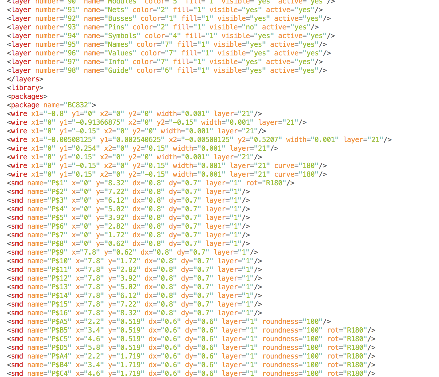
This worked surprisingly well. The most annoying part was needing to conform to a 0.1-inch grid with a file that used metric, meaning that all the spacings were in multiples of 2.54. However, it took about the same amount of time as my previous efforts to reconfigure the grid, and had much better results. Once able to edit the schematic, I re-made the original board that sam had made, and then added in 2 output pins (with diodes for current protection).

As the nRF52 can easily output PWM, but does not contain a DAC (analog signals can, however, be approximated with PWM and a high-pass filter), I decided against using a motor controller for this week, and instead looked at using servo-motors. To mount 2 servos on the board, I used a 2x3 SMD header, into which they can plug straight in. (I did, however, get the order of the pins wrong). In terms of robot locomotion, a contiunous rotation servo is almost certainly sufficient for what I want the robots to do (i.e not move very fast, be quite light), and driving 2 differentially will be enough to get a reasonable steering action.
PWM and driving servos
The servo I chose to use (I won't lie, it was because it was next to my desk), was the fixed rotation SG90. These take a pwm signal of between 1-2ms out of a 20ms pwm period. Using Sam's pwm 'hello world' code from the site, I edited the duty cycle values until I got the servo to move (it was 2am).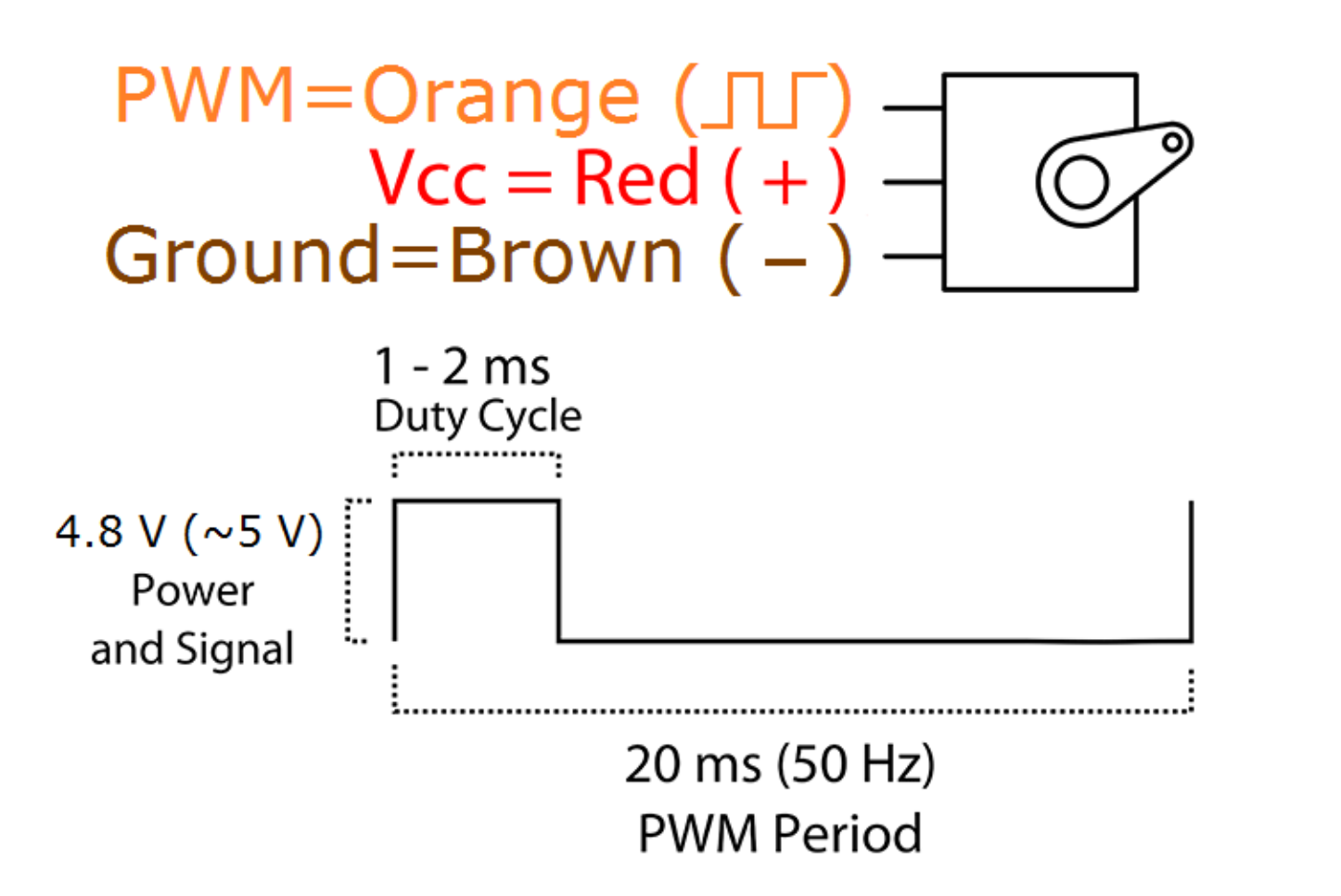
configuring PWM
Later on, with Tomás, we returned to Sam's code to try and figure out what was happening with the pulses. The document nrf52_bitfields.h contains a key to all the commands that can be sent to the nRF52, which was really helpful in figuring out what was going on. The code is written in C, and written to the chip through the Arduino interface. The code itself is pretty confusing, but with the bitfields.h guide it got a bit more manageable.
PWM requires both a duty cycle and pulse width definition. The data sheet for the SG90 servo we were using specified a 50kHz base frequency, with a duty cycle of between 1-2ms. One of the things that had been confusing was that the frequency definition in the code wasn't 1:1 -- the frequency we got out from the chip using Sam's code wasn't the number specified in
COUNTERTOP, which seemed to be the register in which frequency was getting set. However, after a more careful look at the datasheet, we realised that the line NRF_PWM0->PRESCALER = (PWM_PRESCALER_PRESCALER_DIV_1 << PWM_PRESCALER_PRESCALER_Pos); was pre-scaling the frequency base-level, and countertop was just setting the frequency within that. 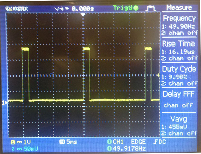
With this, and some help from the oscilloscope, we were able to set a duty cycle --
pwms[0] -- and get the servo to rotate to particular positions. However, we were not able to get the servo to change position within a loop, which we were attempting by using an array of pwms.