Week 5: Electronics Design

Designing the circuit

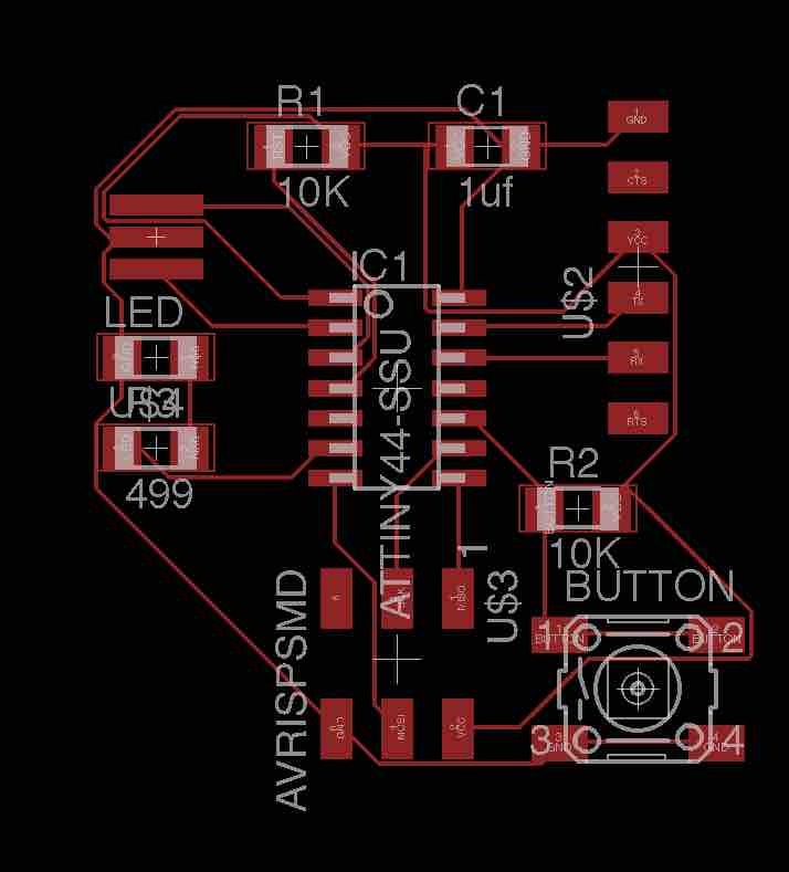
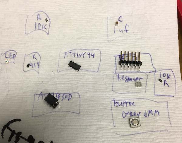
This week I had to add a button and LED to an existing circuit design. I really didn't know where to start for this one, and Eagle has to be some of the least intuitive software I've ever used-- so I followed everyone's advice and Googled for some tutorials. I'd highly recommend Jeremy Blum's Youtube series, which got me up-and-running quickly. I downloaded the electronics library Fab.lbr and then looked through the sample Hello World circuit from last year to see what I'd be making. I was still pretty confused, so I looked through my friend's pages from last year and found links to more helpful information-- like Anna Kaziunas's step-by-step tutorial for her AS220 Fab Academy students. The first step, I decided, was to come up with a list of all the components I needed. Cross-referencing between the sample circuit and Anna's tutorial, I came up with a list that would help me find everything in the Fab components library:

On original board:


For my board:

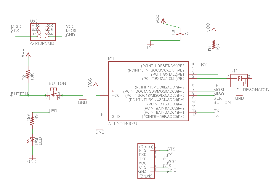
The next step was to add all these circuitry elements to my schematic. Then I had to sort out what was connected to what, and connect things properly-- which was actually nontrivial, since I totally missed the fact that half of my "nets" weren't actually connected to component leads even though they were physically touching in the schematic. (This must be why people prefer to program in Eagle rather than use the UI.) Some time later, I successfully copied the original board schematic into my own file.

Responsive image

circuit diagram

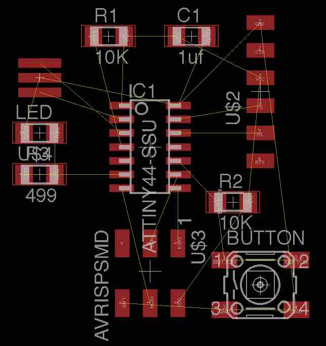
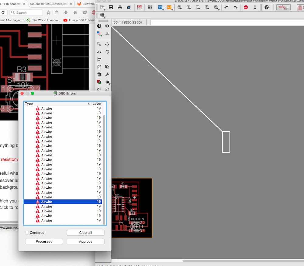
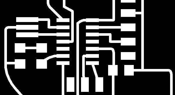
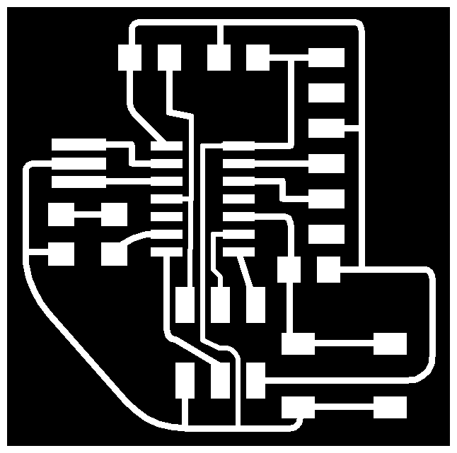
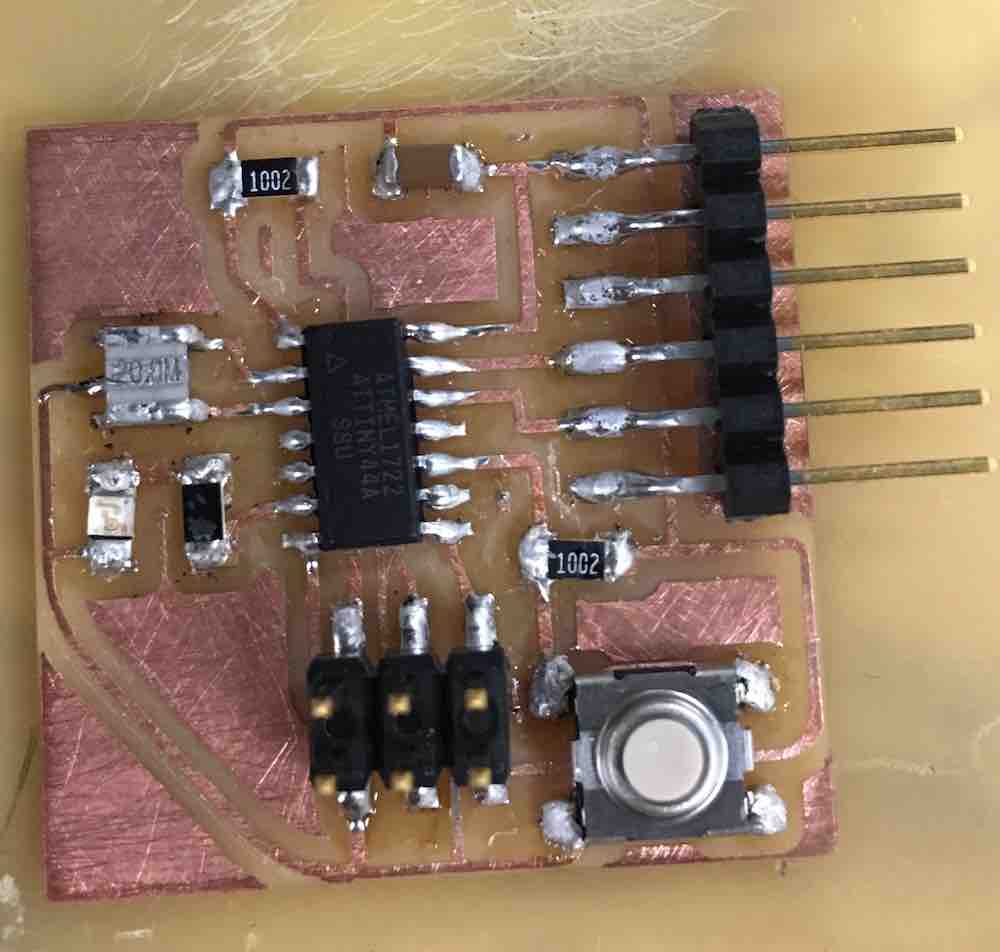
It was then time to create a circuit board. I opened up the board for my circuit and wound up with a spider's nest of little yellow tentative connection lines, which I had to lay out in roughly board-format.

circuit diagram

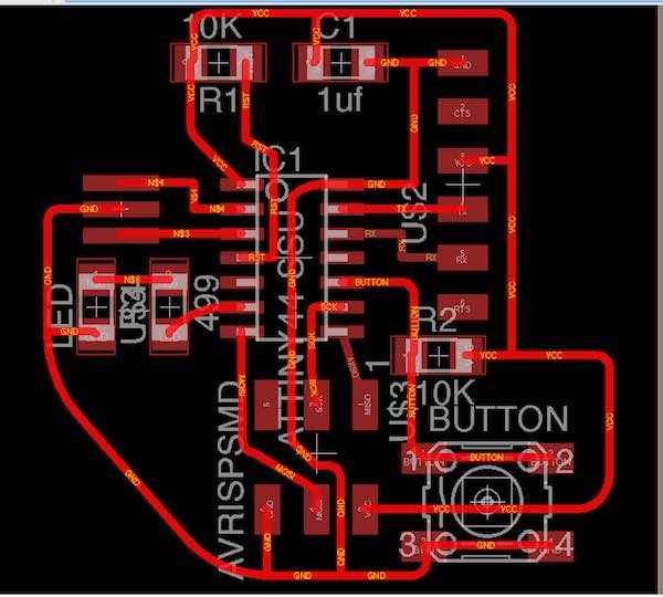
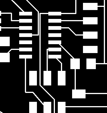
I then tried to auto-route, which turned all the yellow spindly lines ("airwires") into proper circuit traces.

circuit diagram
But they were all too closely-packed together, and a bunch of my connections were missing! Turned out that I had missed even more disconnected nets, so I had to go back and fix things. Finally, I spread out the lines and felt ready to mill-- but luckily I checked for errors first. There was a mysterious disconnected bunch of airwires somewhere which were causing a number of errors, though I couldn't actually find where it was.

circuit diagram
I looked only at the airwire layer and found one culprit after zooming in: a tiny segment of disconnectivity. (Yet again, I was reminded of why everyone recommended using programming commands rather than the Eagle UI.) This solved some of the airwires, but not the other ones... so I saved and quit the program. Upon reopening, the mysterious airwires had all disappeared. Weird. At least the board seemed ready to go.

circuit diagram
The next step was to export my board traces to an image, which I did following Anna's instructions. Opening it up in GIMP, I noticed for the first time that my traces were WAY skinnier than the example traces. I went back to Eagle and found that the default trace width had been set to 6-- but everyone recommended 16!

circuit diagram
After struggling to figure out how to group everything at once rather than one wire at a time, I used the Change tool to change all cables to 16. This turned out much better upon exporting to an image.

Then it was finally time to mill my board! The traces milled out nicely using Mods but, while attempting to mill out the outline, I then learned about two new failure modes on the Modela. The mill wouldn't cut deep enough-- it just kept going around at the same depth, even though Mods was sending it the right commands to go a bit deeper every time. Why not? The answer was one or both of the following:

  • The CBA grad student I accosted explained that the computer's buffer probably developed some issue, so you have to quit the browser running Mods and the Terminal window in which the program actually secretly runs.
  • Tomás pointed out that you can't push the 1/32nd endmill too far into the Modula head, because then it can't be lowered properly.
  • circuit diagram
    I also turned the Modela off and on a few times, for good measure. Eventually, it milled out-- and then I looked at the milled board, and saw that some of the traces were overlapping and I'd missed one of the connections to the ISP.

    circuit diagram
    Back to the Eagle drawing board, where I added in the missing connection, shuffled everything about, and then made the traces under the microprocessor width 12 to ensure that they didn't overlap with other traces after milling.

    components
    This board turned out much better, so I picked out all the components I needed and then set about soldering.

    circuit
    Some of my solder joints turned out cloudy, so I tried to reflow them. The button was particularly difficult to solder on properly, since the pins were placed awkwardly high above the actual board, but I more-or-less got them soldered.

    circuit
    All the joints seemed solid, so my board was ready for programming.

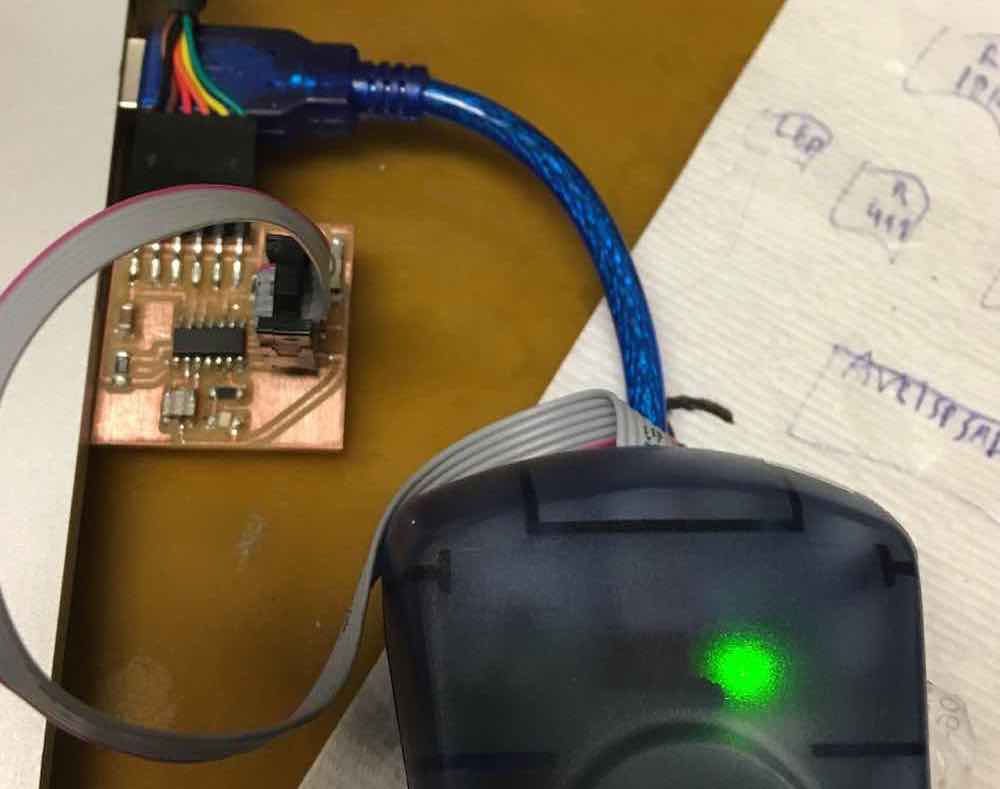
    Thras said we should be able to get our boards working through the Arduino app, so I followed his steps to set that up:

  • Download Arduino IDE app
  • Install ATTiny support software for Arduino following the guidance from High Low Tech.
  • Select the right board, resonator, and programmer from the Arduino settings
  • Run the "Burn Bootloader" command under the Tools menu
  • Write and upload programs
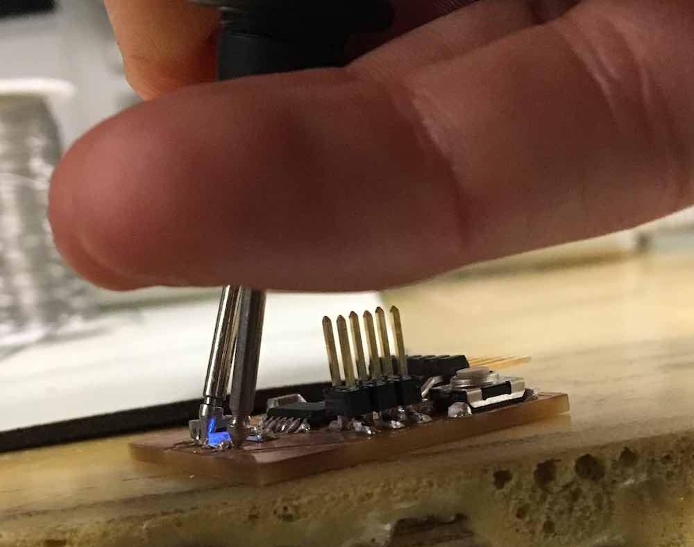
  • My LED was definitely working, and the programmer lit up properly...

    ...and then the blink code I tried to run within Arduino didn't work at all. Argh. Then Oscar helped me try out the suggested Hello World tutorial, which worked beautifully within the Arduino app, so my board is mostly functional! Success.

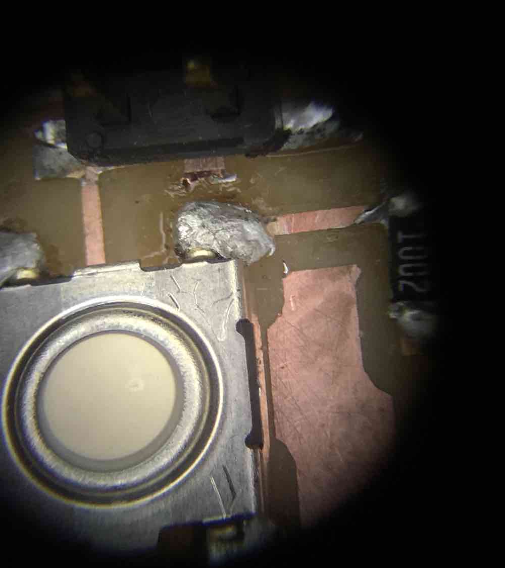
    What went wrong with the blink program? Everything checked out on the multimeter, so it's hopefully an issue with the program. Stay tuned for Week 7, when I'll learn how to program electronics and we'll check back in for some debugging excitement...