How To Make (Almost) Anything
To the end!
Photogrphers use a lot of angles to show many different perspectives. In my work in the past, I've tied a tripod to a bus, dangled a gimble from a vine, and even attached one to a lazy susan.

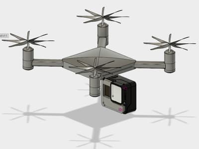
The problem is that all of those are unstable and niche. One of the common things people are now using that remains stable is a drone. I was hoping I could attach a drone to a camera
Update 2
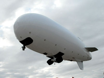
Looking in versions. It seems a blimp is also an alternative, but they are rather large and would need helium to rise and fall. The other problem with blimps would be the propulsion. How would you get them to move in a straight line? You could use fans. In which case you would need four cardinal fans. It would also be interesting to see if you could get one on top and bottom to control the height. In this case, weight control would become an interesting problem as the ballons are normally very light and that's how they fly. Furthermore, how would you attach these fans to the blimp?
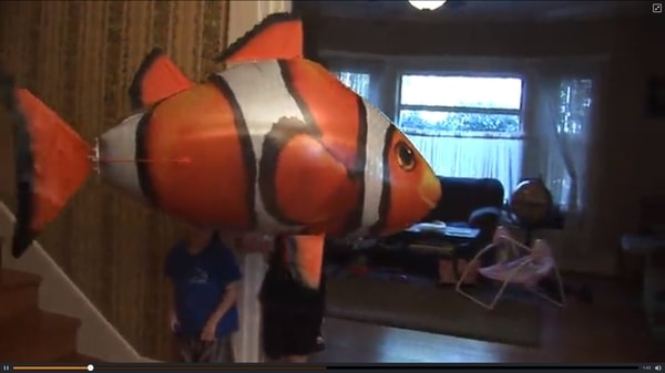
I looked on Amazon and found these floating nemo blimps. It seems they they do fly quite well and are able to maintain their aire control even with the electronics attached.I have ordered some of the material for them as well.
Update 3
I can use a Stepper Motor to drive the fins of the ballon.
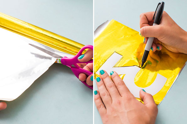
Helium balloons are made of Mylar. Mylar can be can be cut using the vinyl cutter and then sewed together using the technique tom taught us together. I can also imagine decorating the balloon with Velcro as well.
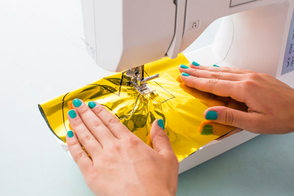
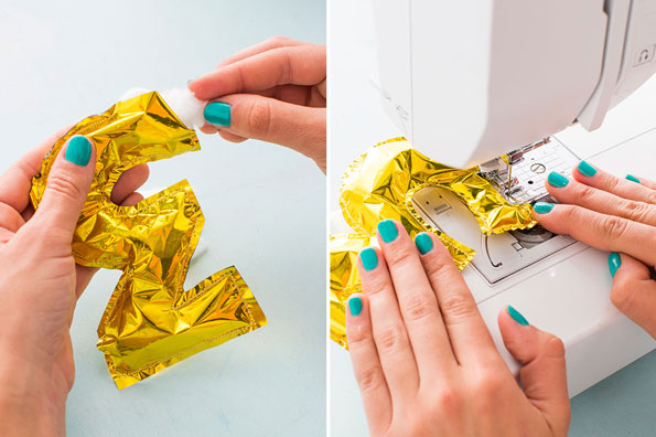
Sadly, those images make it seem easier than it was!
I was able to get some balloons that Anna had made. I thought that I might be able to just inflate them and put my electronics on them. Sadly the balloon was unable to carry more than .1 pound above its own weight. Furthermore, when I tried to put my electronics on the balloon, it popped from the pressure!
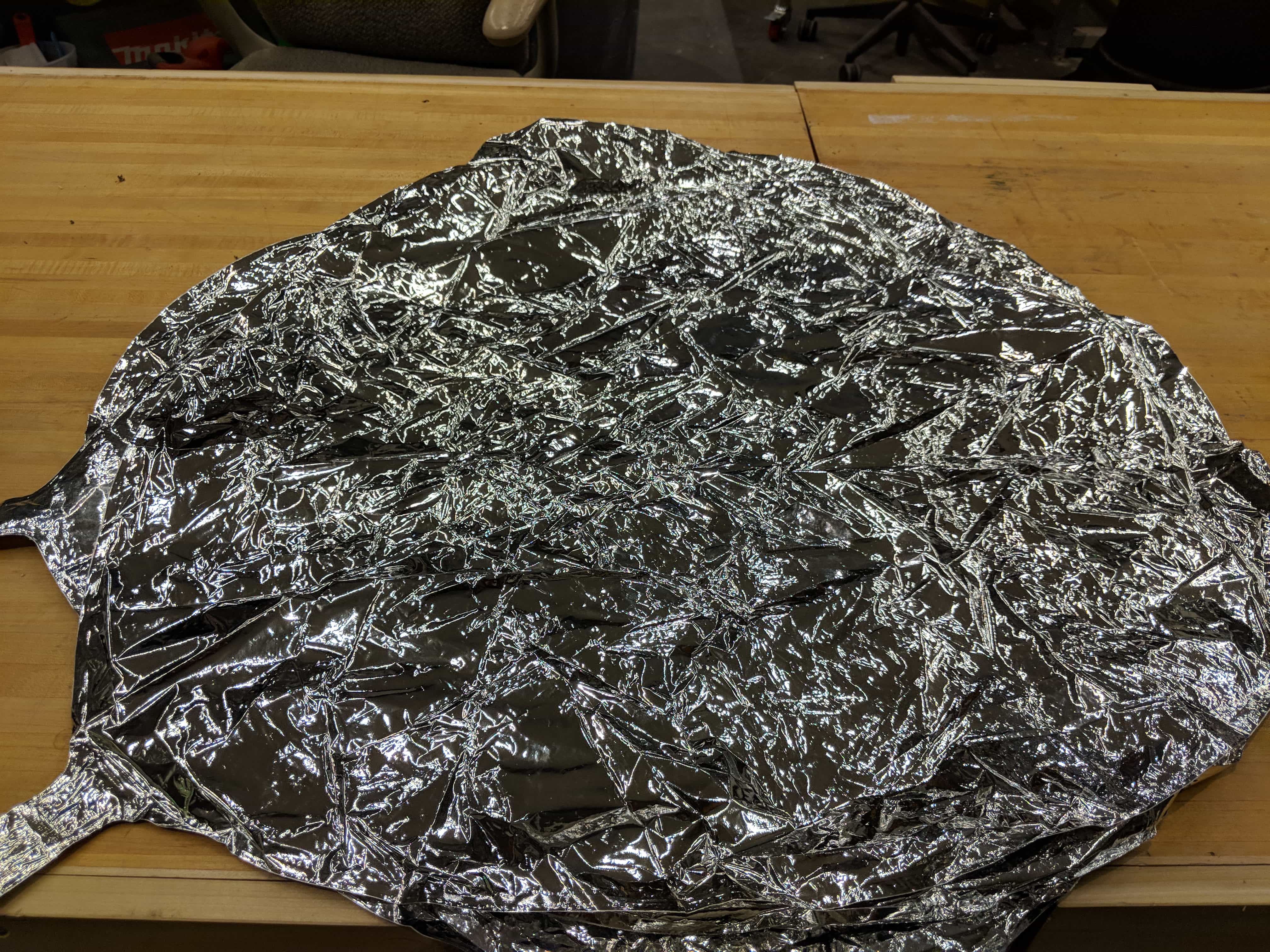
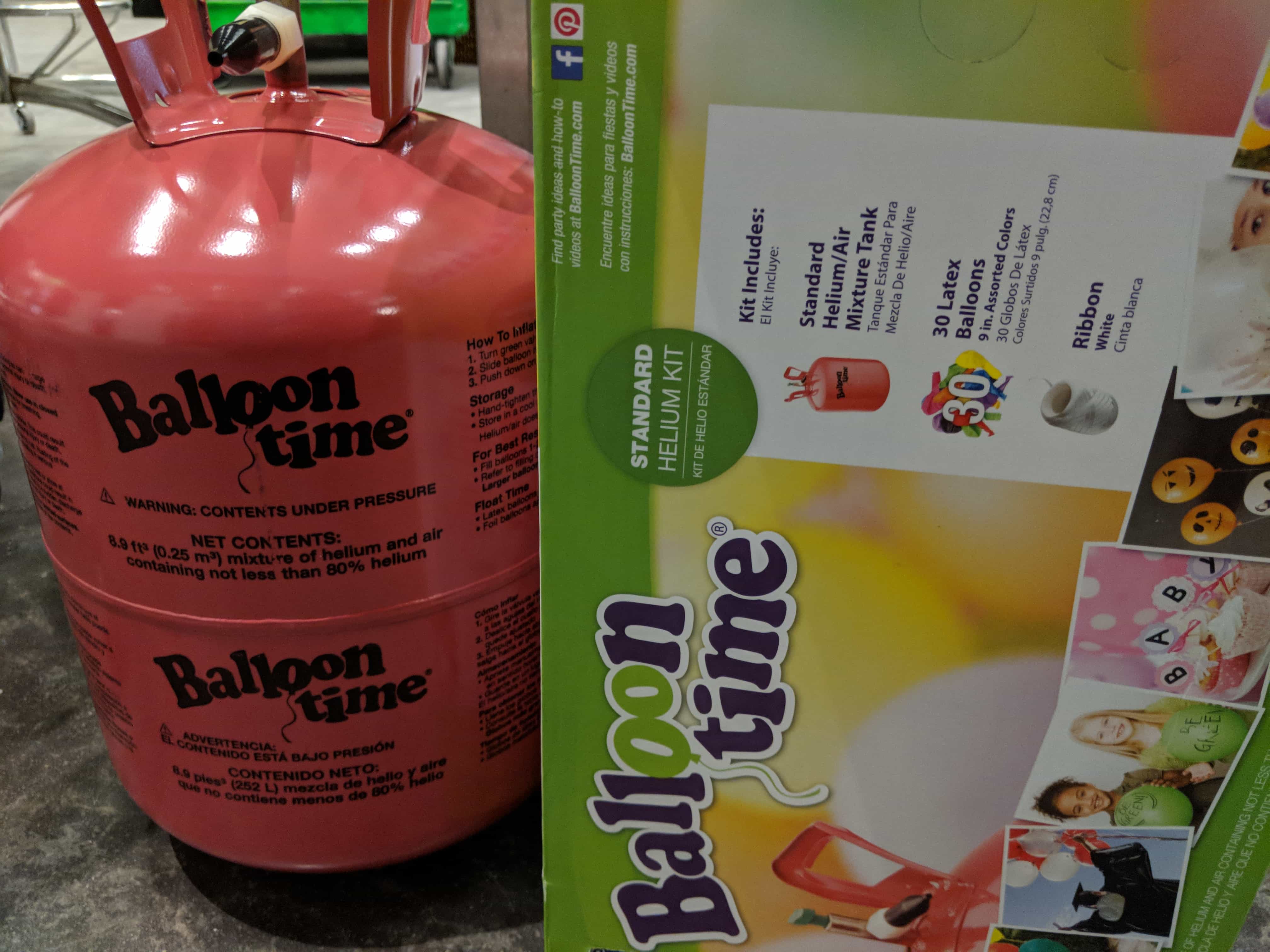
I ordered a giant mylar roll that was twice as thick on Amazon and I also bought a tank of helium from Target. I figured that if I was able to make a giant mylar balloon it would be able to hold all the weight at some diameter as volume (and lift) grows a cube whereas surface area (and the downward force) grow as squared.
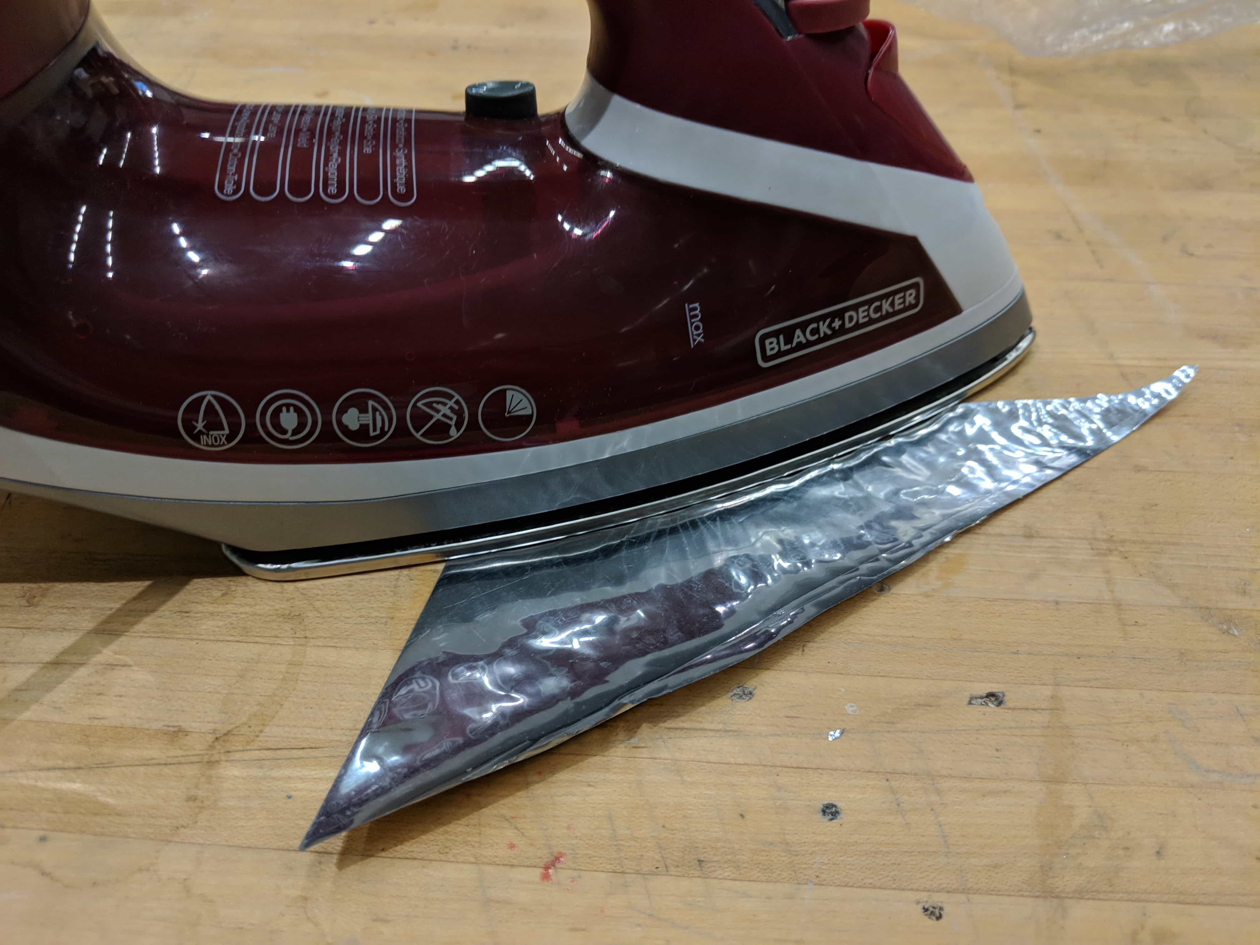
When my Mylar arrived, I tried sealing it. Mylar is supposed to form a vacuum seal when it is heat even with a home iron or curling iron. I tried for hours with my pieces, but wasn’t able to get it.
The iron did nothing but left indentations in the foil.
I tried using the hot air gun in the electronics lab but it burned the mylar!
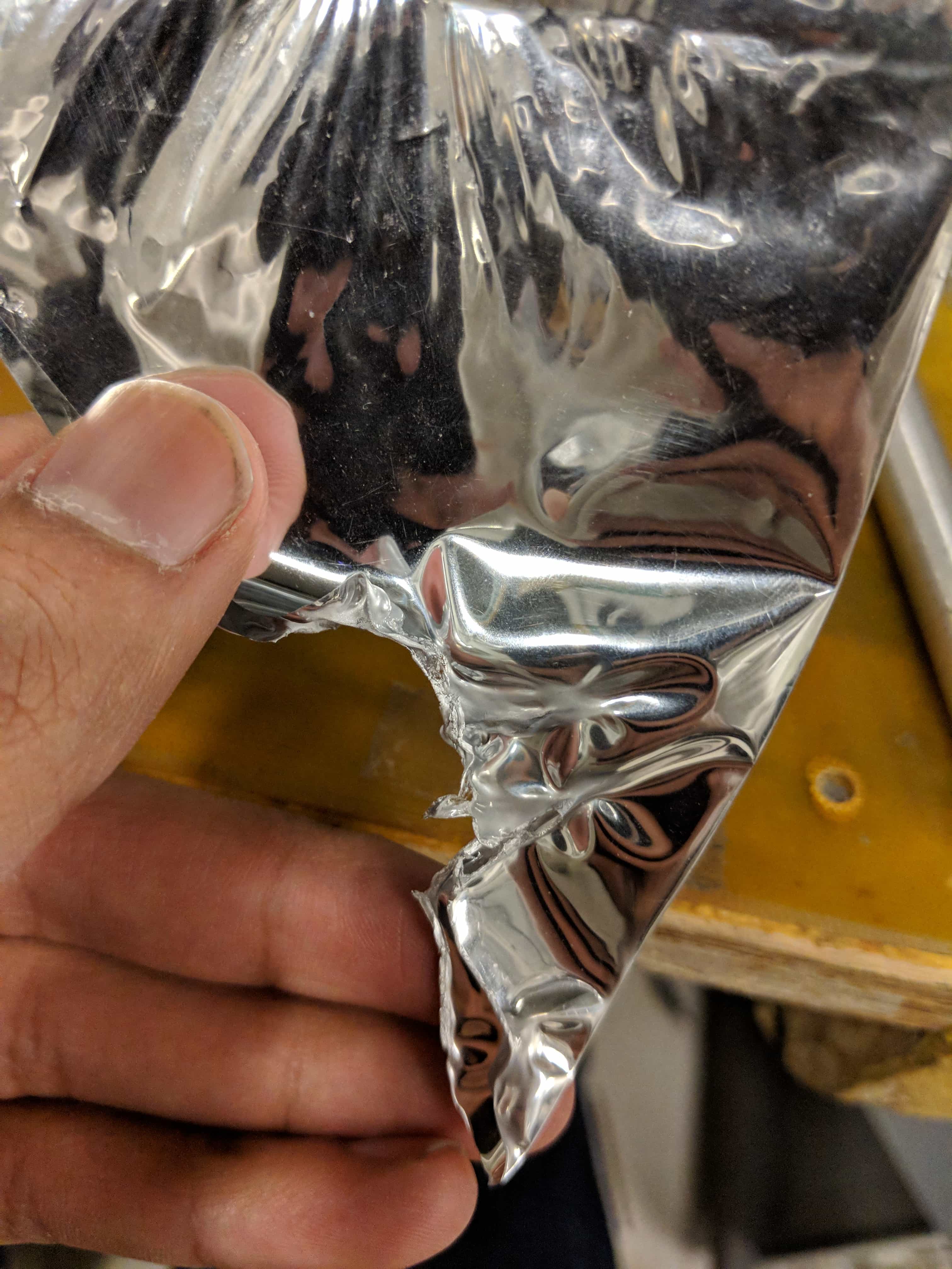
I tried to heat it at every 25 degree interval from 300 to 800 with the soldering iron. It either didn’t stick or it burnt!
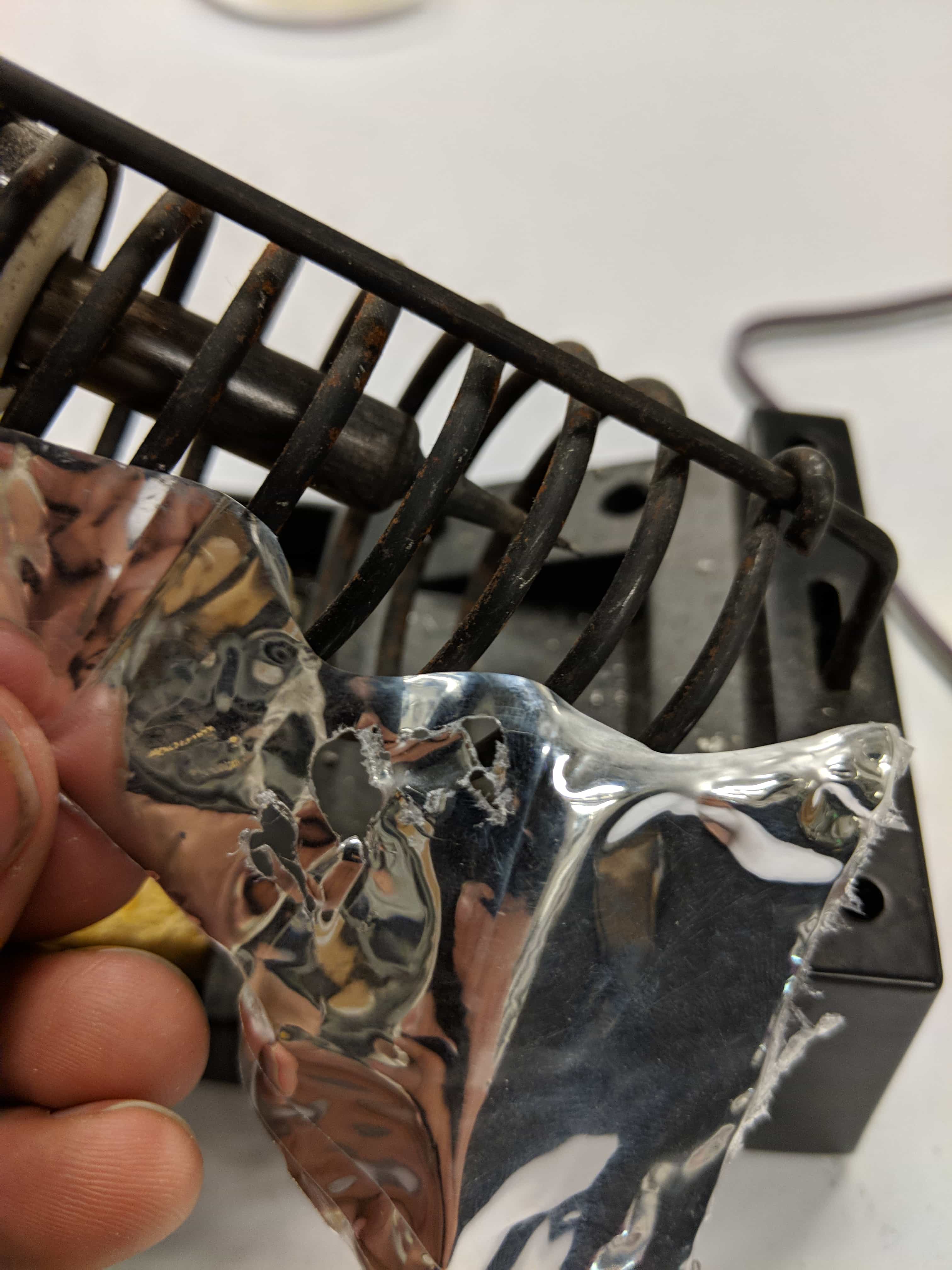
I figure that the way that the vendor made the mylar thicker was to place some sort of plastic binder in between two thin layers. This had the effect of making my Mylar not stick and in fact burn with heat. This was shown in effect when I took the balloons Anna gave me and saw that they stuck to each other with heat.
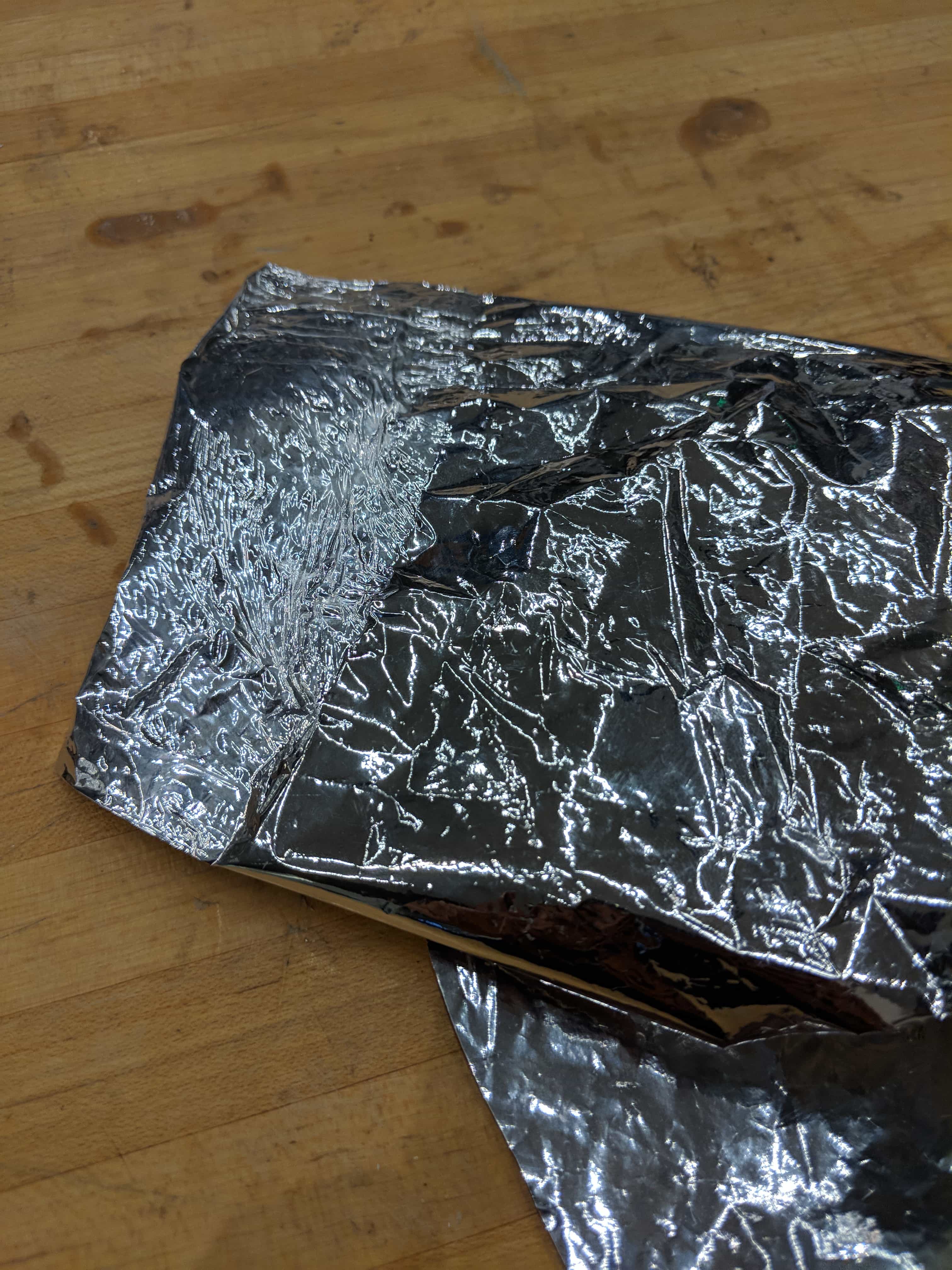
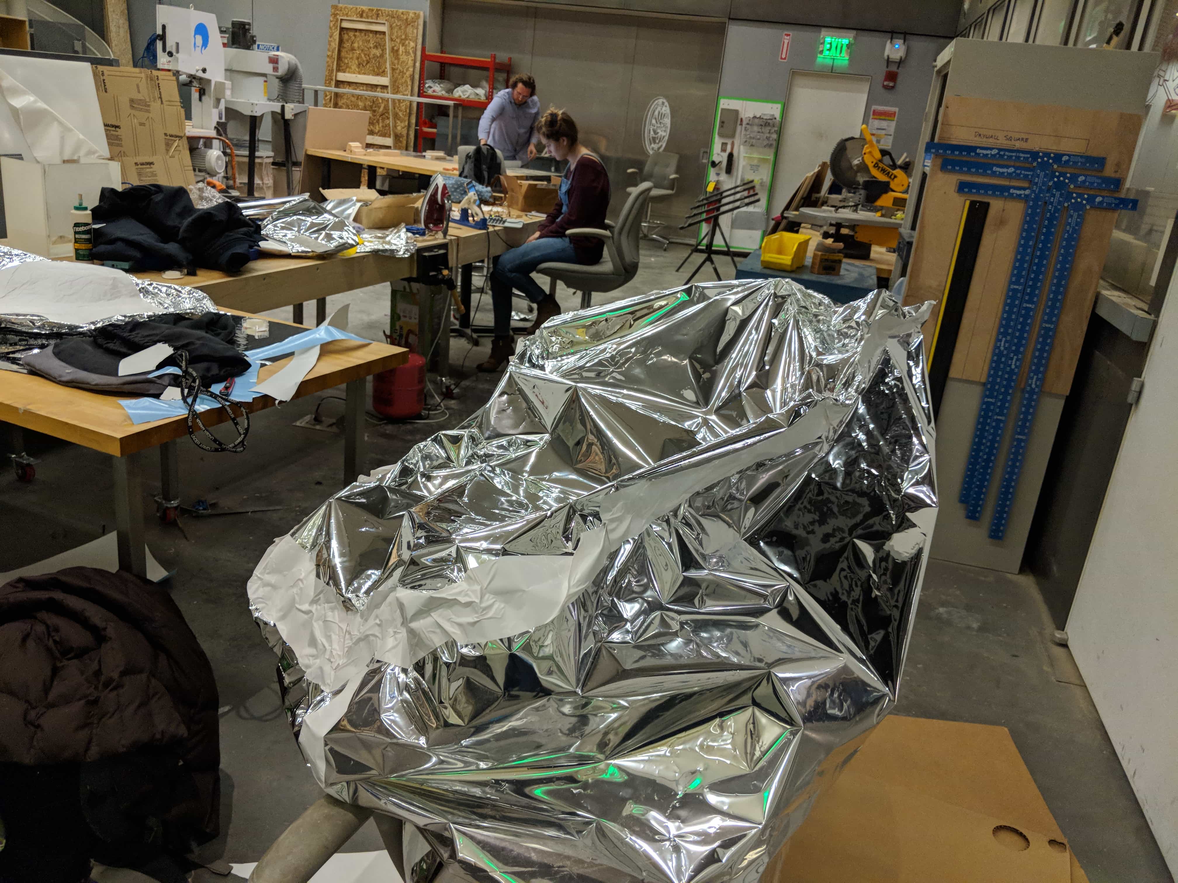
I then decided I could take my Mylar and stack it with double sided tape and vinyl because vinyl kept air bubbles trapped often. I used the vinyl cutter to cut the vinyl into perfect square sheets that I then used the tape and vinyl to stick together into a giant cube.
I used cardboard to hold the pieces up while I taped
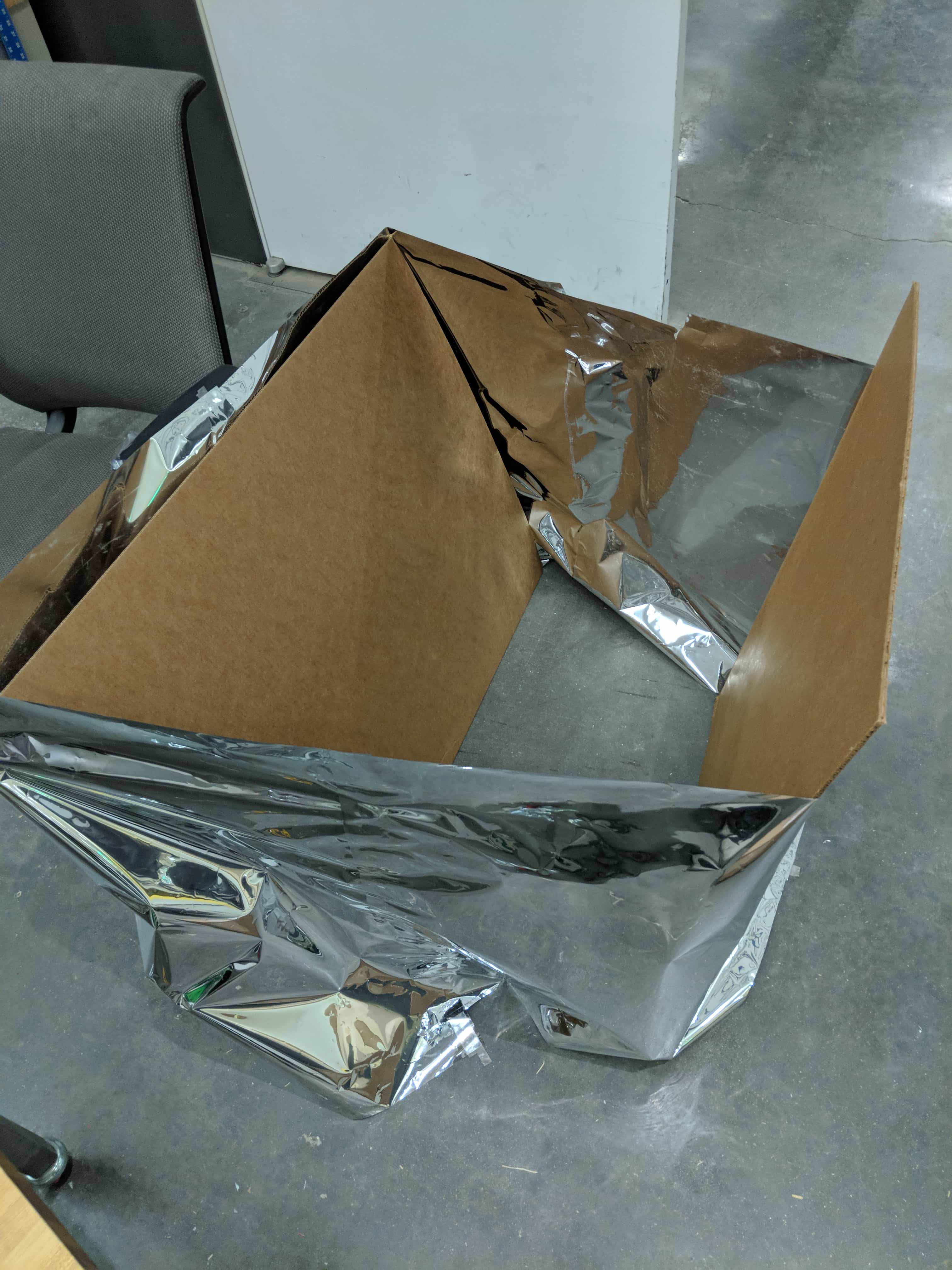
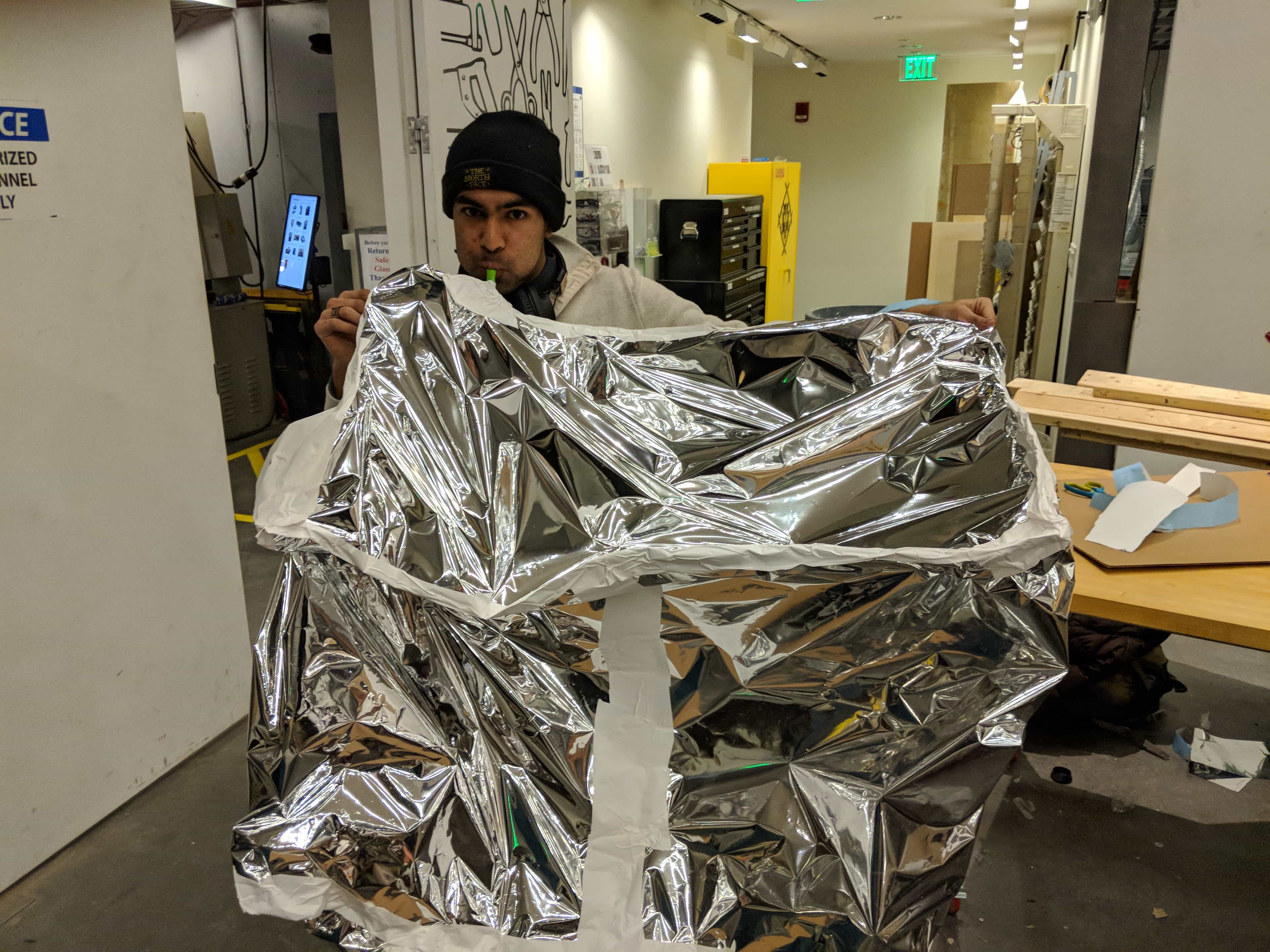
They seemed to hold really well and seemed almost seamless
I added extra vinyl over any areas that weren’t completely covered.
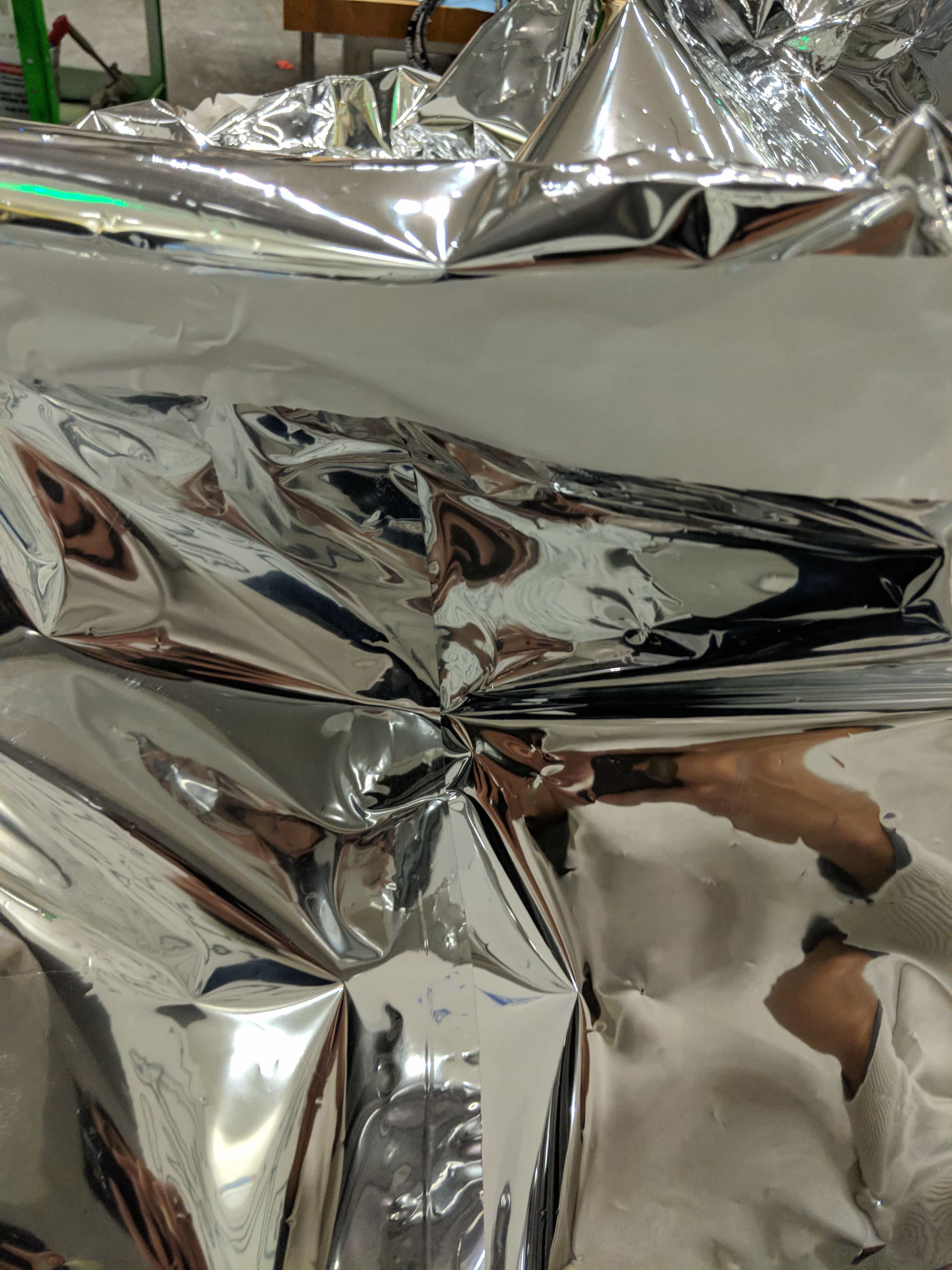
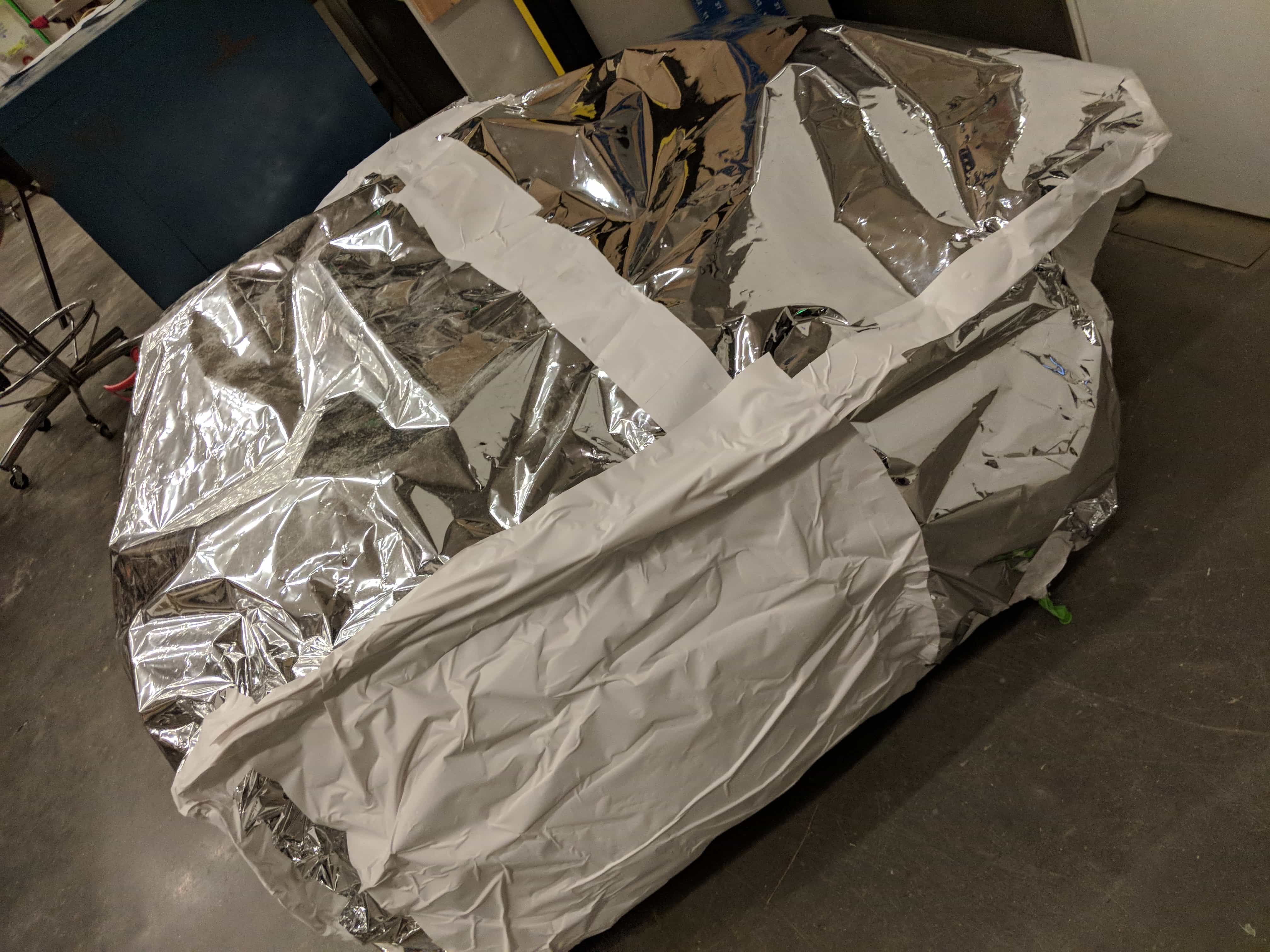
Then I tried blowing it up and I found there were holes. I tried to cover all of them up but I just couldn’t seem to. I tried submerging the balloon in water, using dish soap, and finding the holes by hand.
I then decided to try blowing up all the balloons and stuffing them into the big balloon. I ended up needing to buy a second helium tank. Even with two tanks full of helium I wasn’t able to get it to float!!!
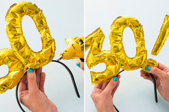
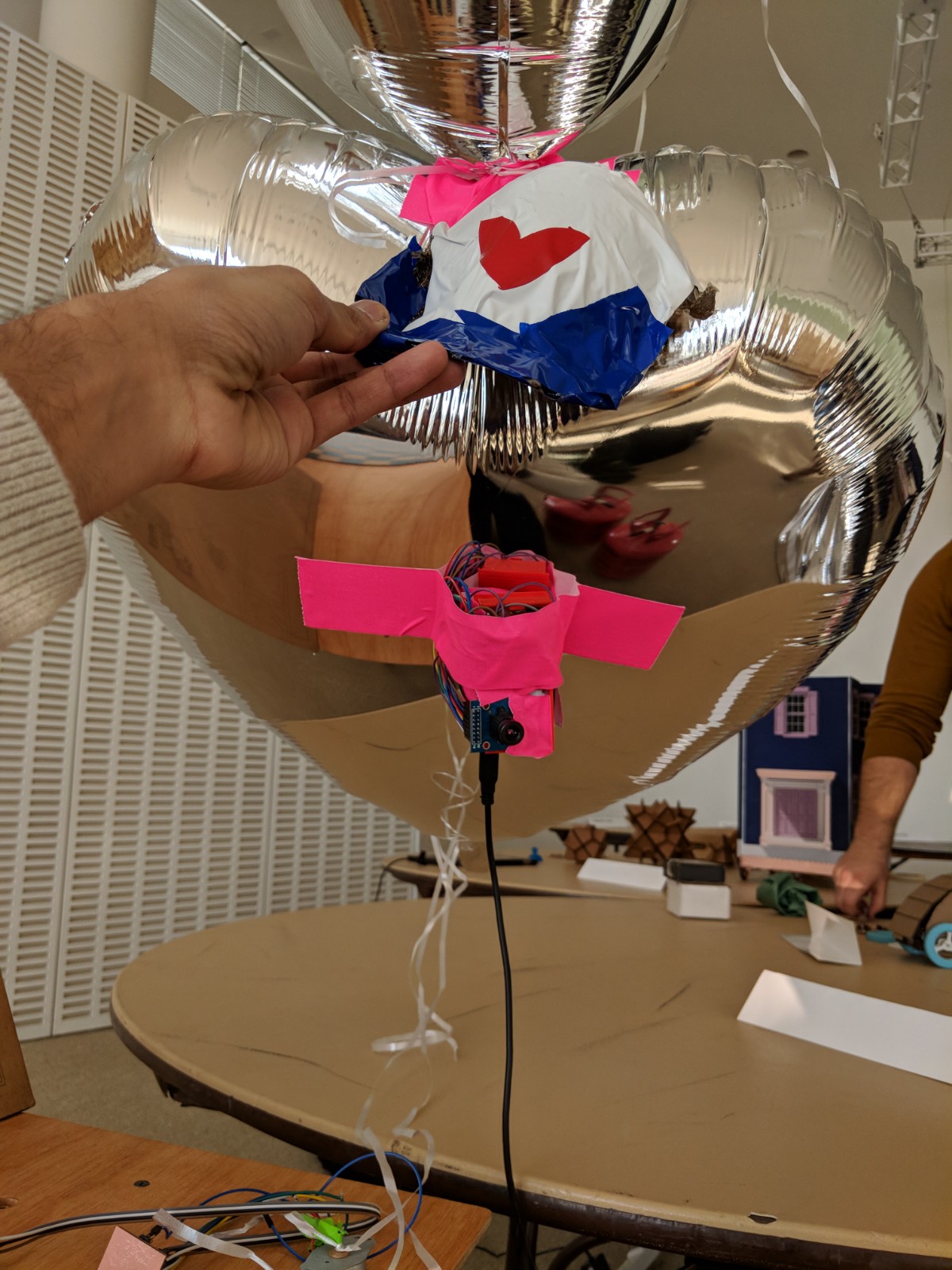
After talking with Anna and Pinar I decided to shift focus and go with the heart theme and make it something for my girlfriend. I ended up stacking the existing balloons into one figure.
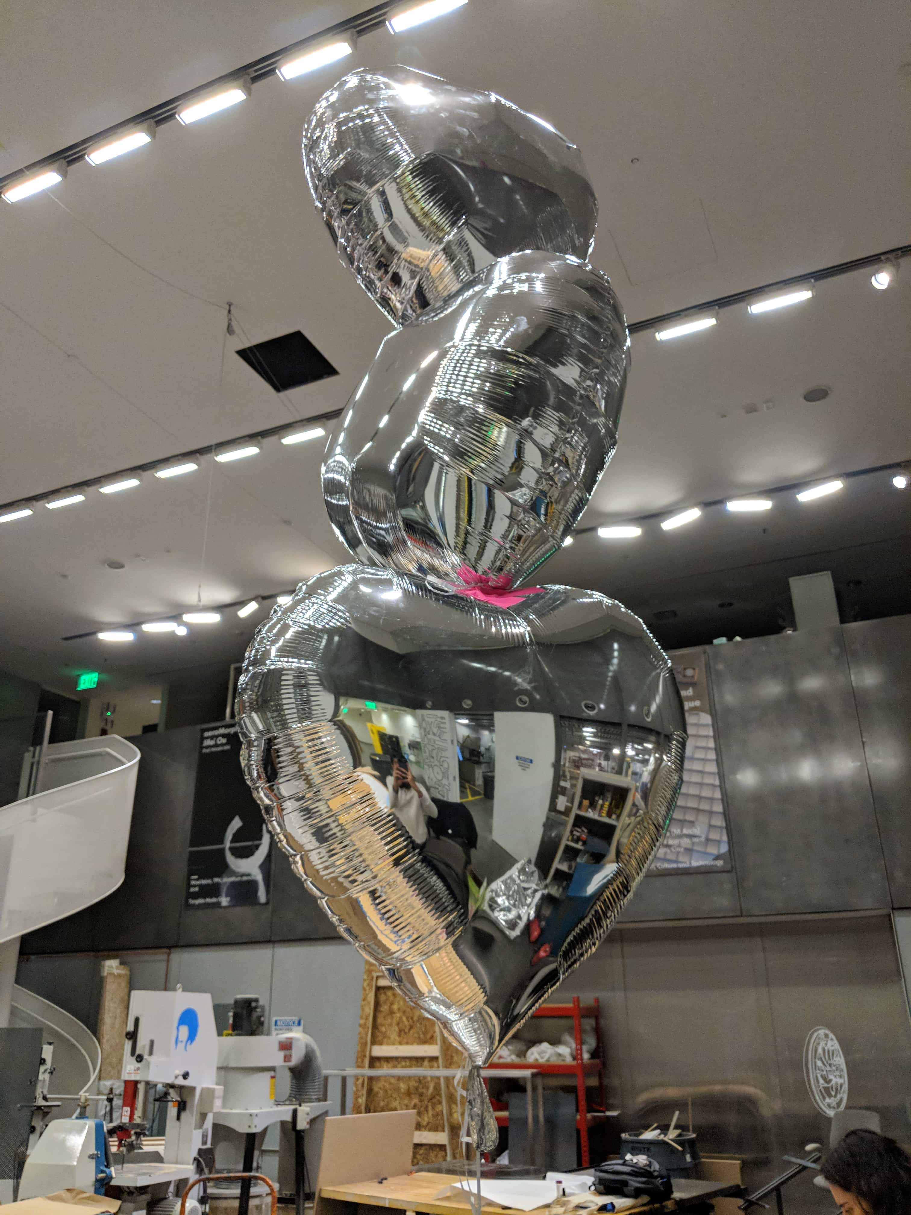
Now with these ballons there were four other pieces to add: a turing stepper motor, a camera, a burlap hat, and some lights!
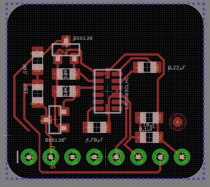
I based it off Niels design but I wanted it to also be BLE compatiable so I had tobe thoughtful. There weren't many pins availible in the sample design so I decided that I could use a trick for the usb programmer. Have the isp header first send out signals to program the board which turns the miso and sck keys then into rx and tx using arduino serial. The sample board used several components including a 10k resistor, a 6 pin isp header, and an ATTiny44. These pieces are simple enough after the prior weeks, however introducing the stepper motor and understanding what “T1 N” stood for took some time. I decided not worry about the BLE until networking week.
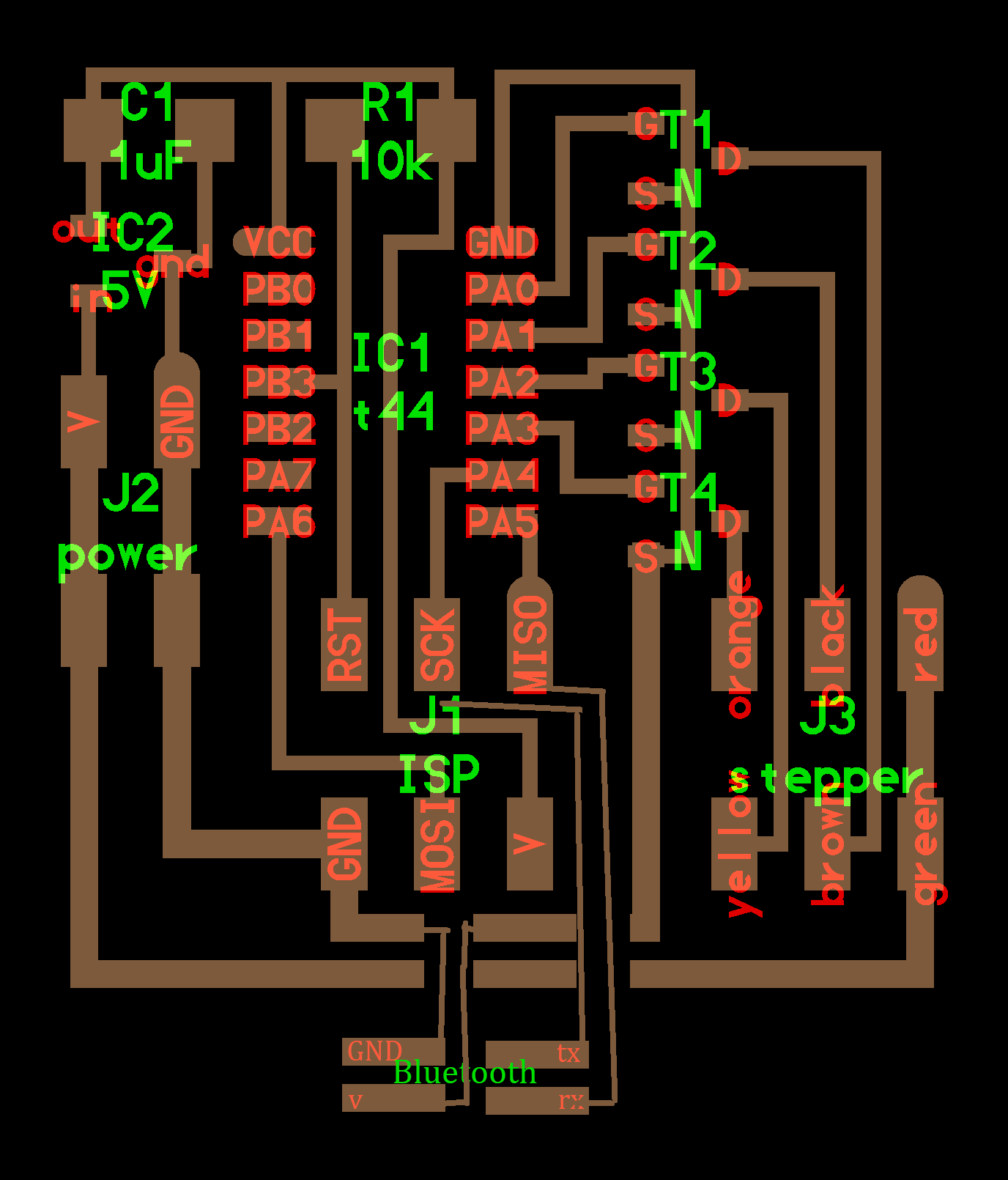
Issue 1: “T1 N” – Figuring out what T1 N stood for was actually a little more trouble than it seems. The board in general uses several short hand acronyms from IC to R. If you look online for those symbols there are simple translations “integrated circuit” and “resistor.” However, “T” proved to be more difficult – it was default written as transformer. I looked all over the electronics shop for tiny three pin transformers labeled “N.” None exist. I also found it suspicious that four transformers were needed and that they would come in such small packages. Eventually after discussing with Tomas, I was able to figure out that “T1 N” actually stood for transistor – specifically an N-type mosfet.
After this step, I was able to mill out the board and attach the components. Unlike the last two electronics week where I shorted and burnt my circuits, this week I was actually able to solder a working circuit the first time!!
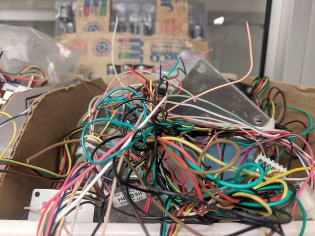
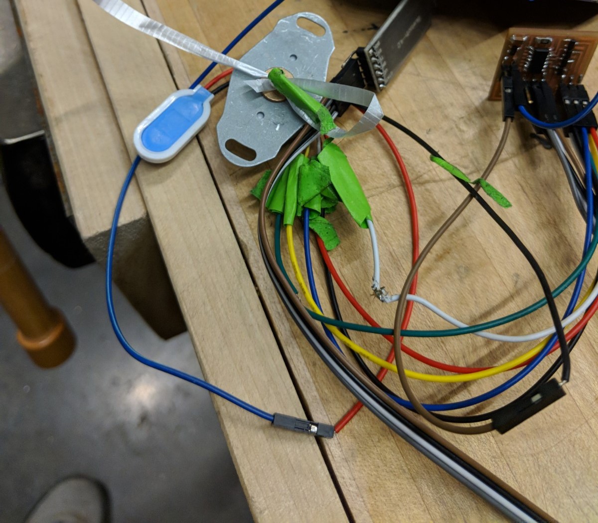
Issue 2: Figuring out the stepper motor. The sample board above uses a stepper motor with orange, black, red, yellow, brown, and green color wire insulation. Good luck finding that color combination anywhere else. Searching all over the web and through all the other motors in the shop, I could not find one motor that match the one in the sample. This naturally indicates that one should look at the data sheet. Sadly, all the motors in the shop were bunched together in a big ball so not only were they difficult to separate, they were also unlabeled and I was unable to find their data sheets.
In the end, I had to be a bit cleverer. In most unipolar motors have six wires, but they can also work with 5 when the center wire in the arrangement is connected. Often times even in six wire connections the center wire is connected outside the module. In the sample board, they were connected together and to vcc. I decided to use the multimeter to test the resistance. The center wires should have half the resistance to the ends than the ends do to each other. I used this to find the “red and green” wire in the board which on the stepper motor were actually “brown and orange.” I also decided to connect the other four wires randomly, hoping for the best.
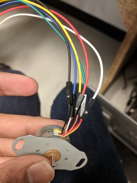
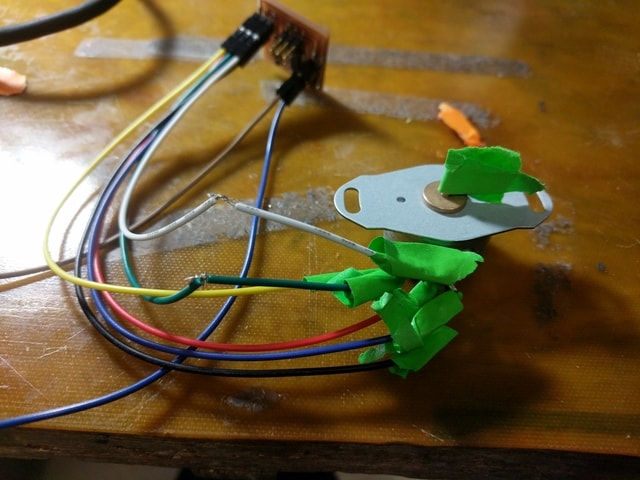
Issue 3: Wiring. Now there were the six wires on the stepper motor and I wanted to connect them in the same pattern as their corresponding color on the sample board. Sadly, the stepper motor I was using was the only 5V motor I could find and it had really short wires. Furthermore, in general to connect the wires together I would need a female-to-female adapter. I found six separate wire adaptors but as I attached one another would fall off and the small wire sizes gave even less room for error as I moving a wire meant essentially moving the motor. In the end, I decide to cut the female-female adaptor, tin the wires on the stepper motor, and then solder them to the adaptor.
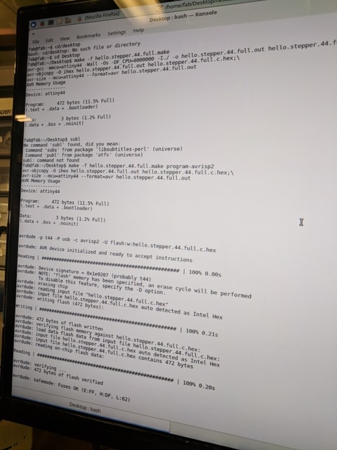
Then it was time to program the ATTiny44 with the code I would need to move the motor. I also here used the sample motor provided. I was so scared the first time I plugged in the programmer to my board and my laptop to find it growing red. It turns out I forgot to add the 9V battery. I almost cried when I glowed green!!
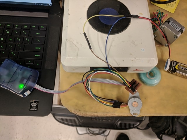

Finally from there, I was able to launch the sample code and test the motor.
In the end, it seems that the motor had something stuck in it or there was something I couldn’t find in my code to get it to revolve by itself. But with a push, I was able to get the motor working!
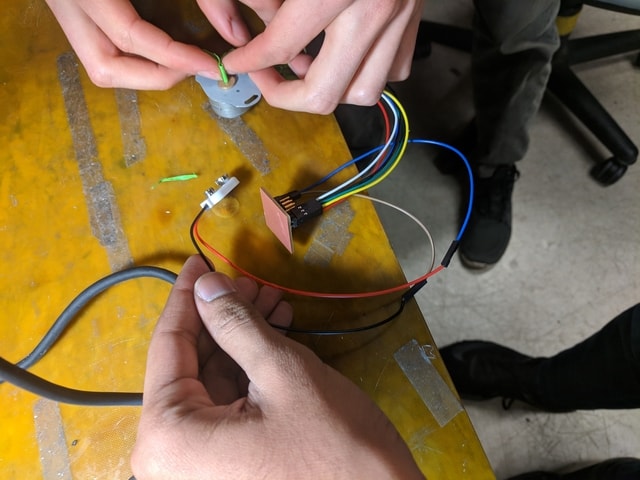
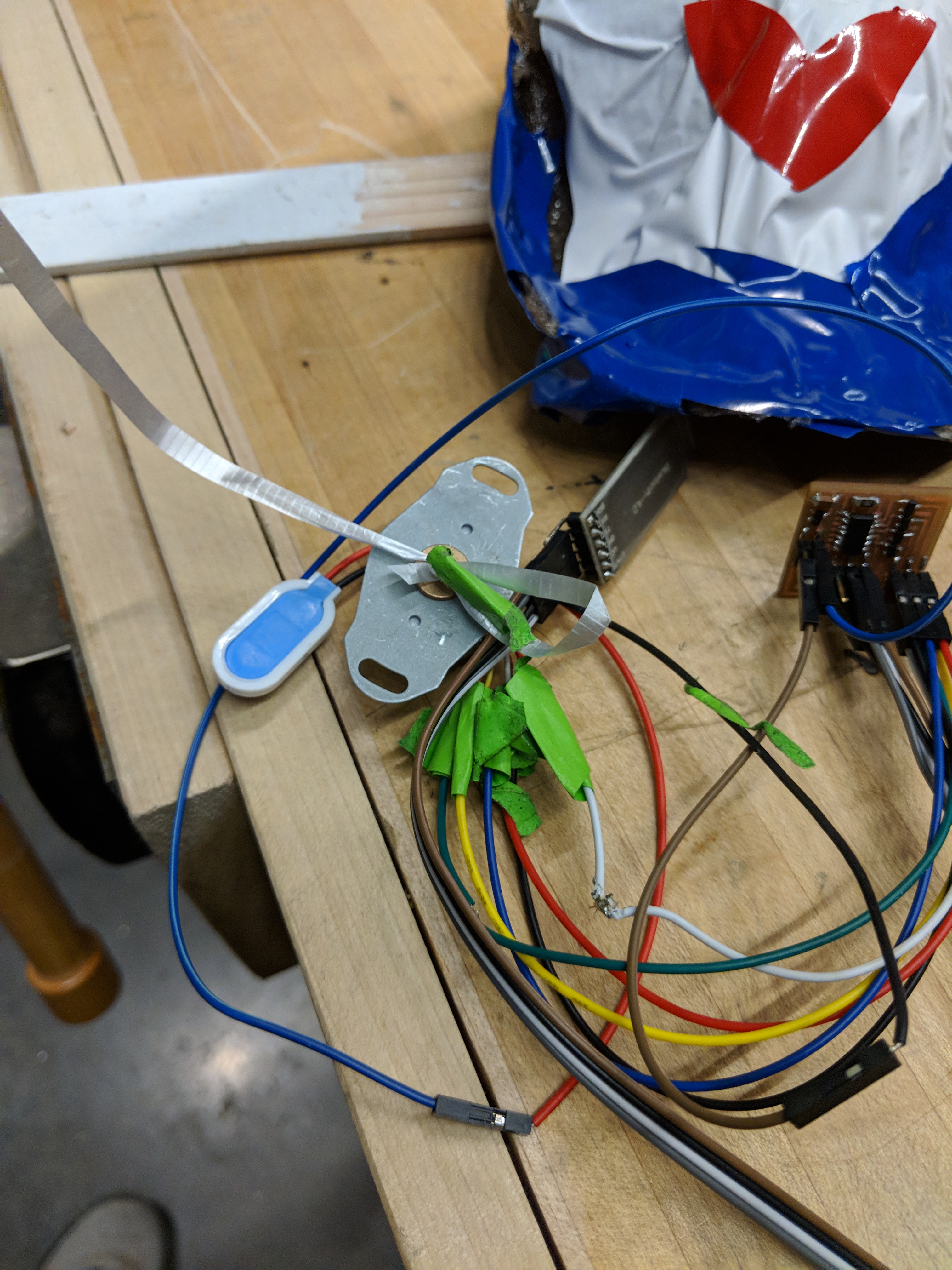
I was able wire up the cable as shown above and conect it with my computer.
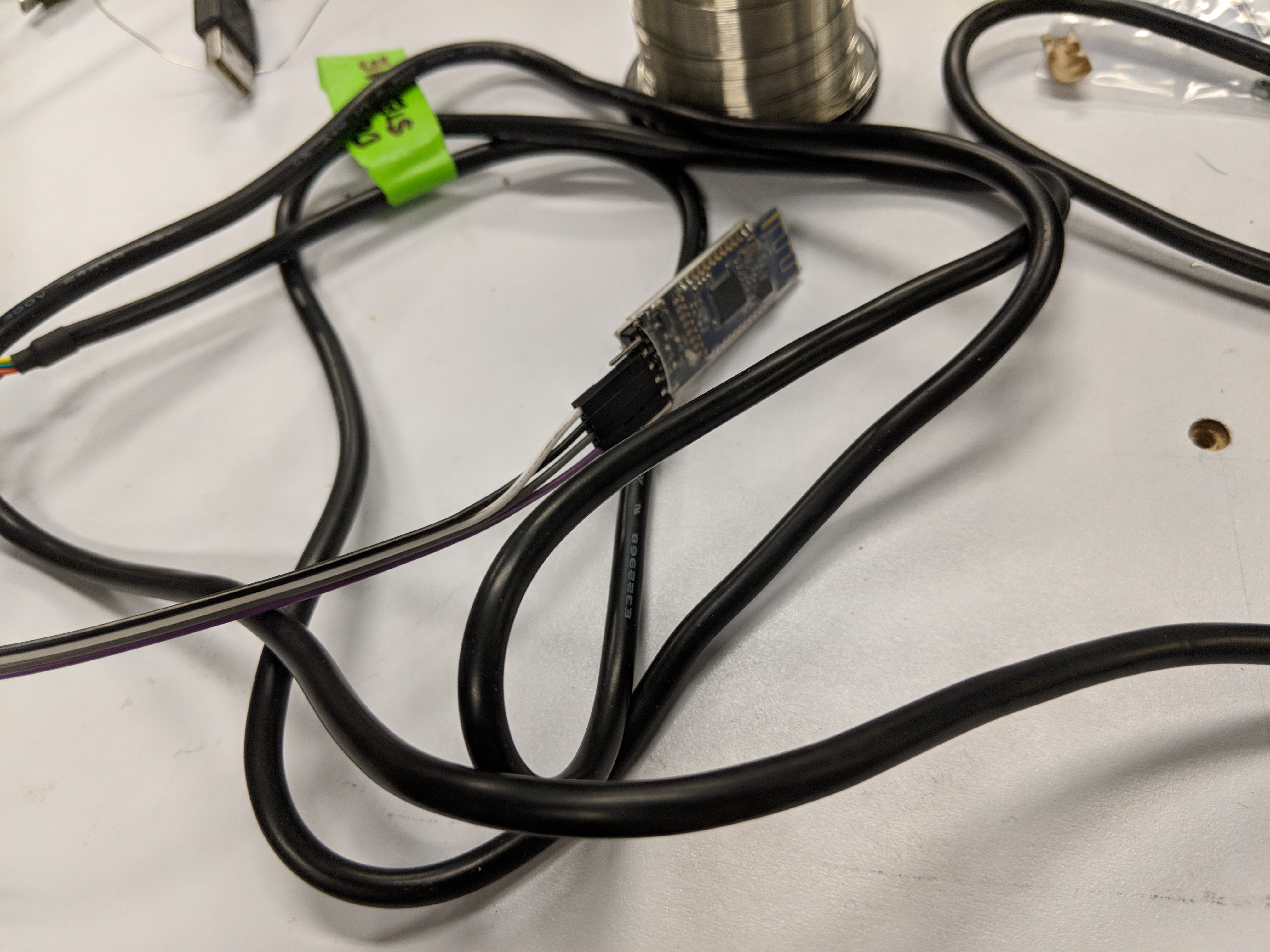
Then I took the other bluetooth cable and connected it to my computer as well with an fdti cable.
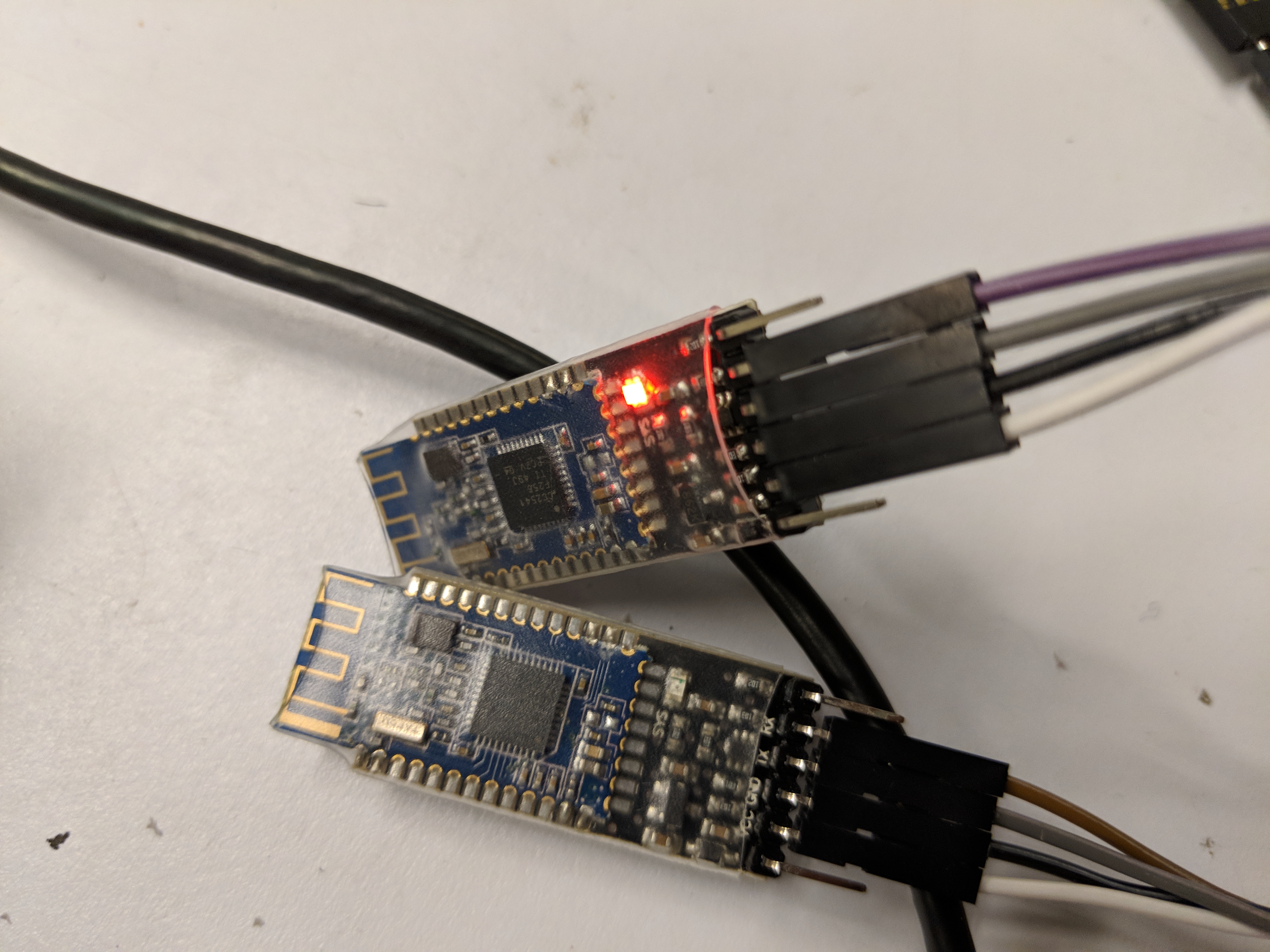
I was able to check with AT+NAME? and AT+ADDR? to see if the bluetooth modules connected and I was able to connect one bluetooth module and load some directions to it for the stepper moter.

The other bluetooth module I had became unresponsive and while it still looked fine and worked on the multimeter - it struggled to produce a viable connection I could use.
I was able to get these pieces together to have something that could turn my ballons. Now for the camera!
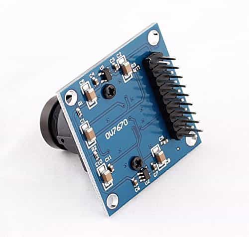
I decided to try and use the arducam – which I hoped to use for the final.
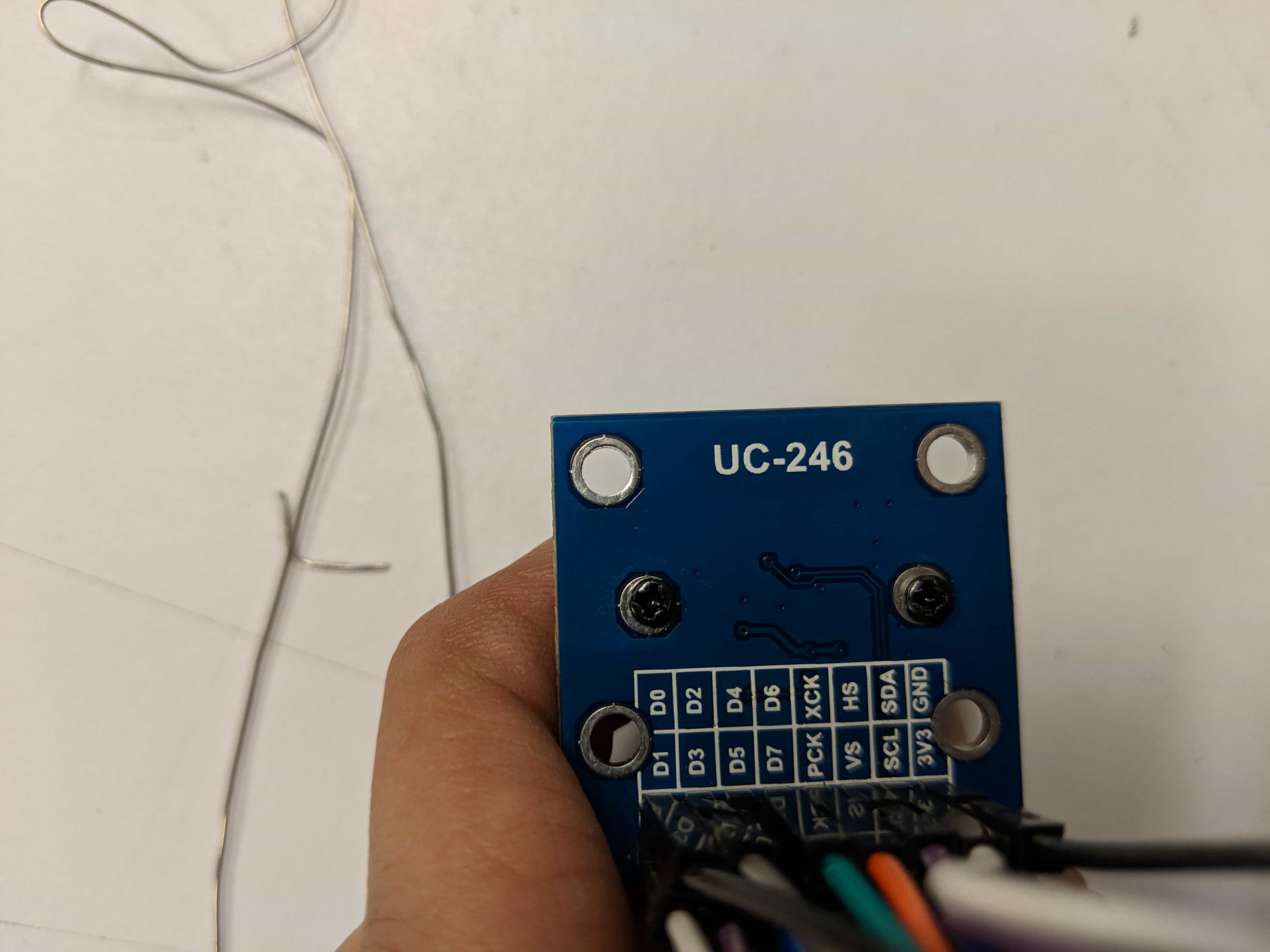
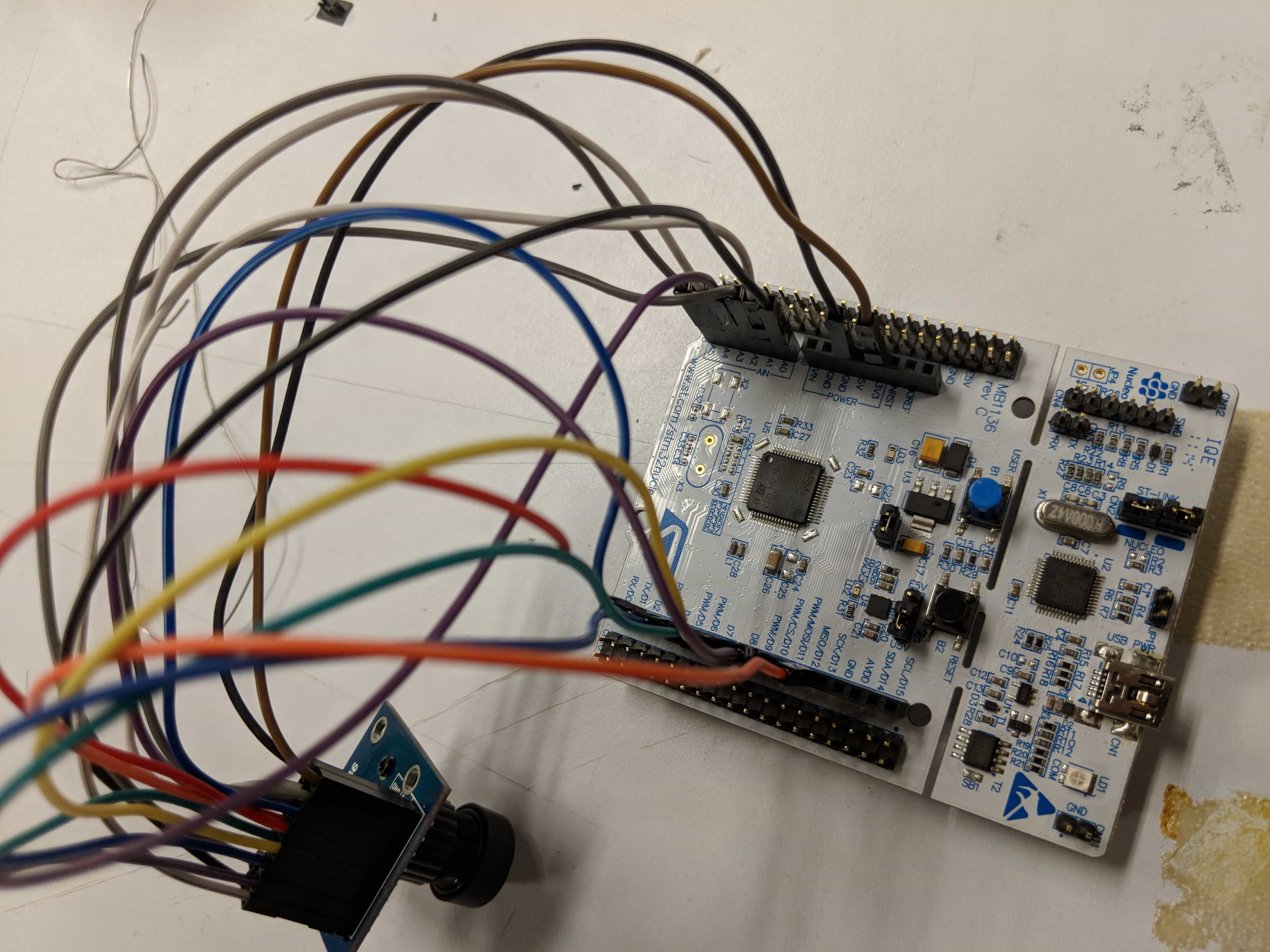
I soon realized that it was quite difficult to use for two reasons. One it had 16 pins so there was a lot of data to manage. A lot of the online resources on how to use the camera used the Arduino due or an uno with a shield. Both of which for my purposes and this class are less than ideal. Furthermore, they all used a different version of the camera. You can compare the amazon version (first) to my version (second); there are less pins and quite a few less components on board. I nor any of the TAs I asked were really sure what was the exact differences were.
I did find a useful instructables tutorial that laid out the pin connections with an Arduino uno. As I became convinced that I could not find another way to use it, I decided to try it out.
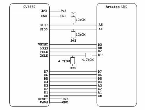
I did feel that I could at least make my own board for the resistors and other components that acted between the Arduino and the camera and so I did.
At first, I tried using the stm128 to find the key to using the camera step but step, but I really couldn’t figure much out. I decided to full on use the uno and and was able to put something stable together.
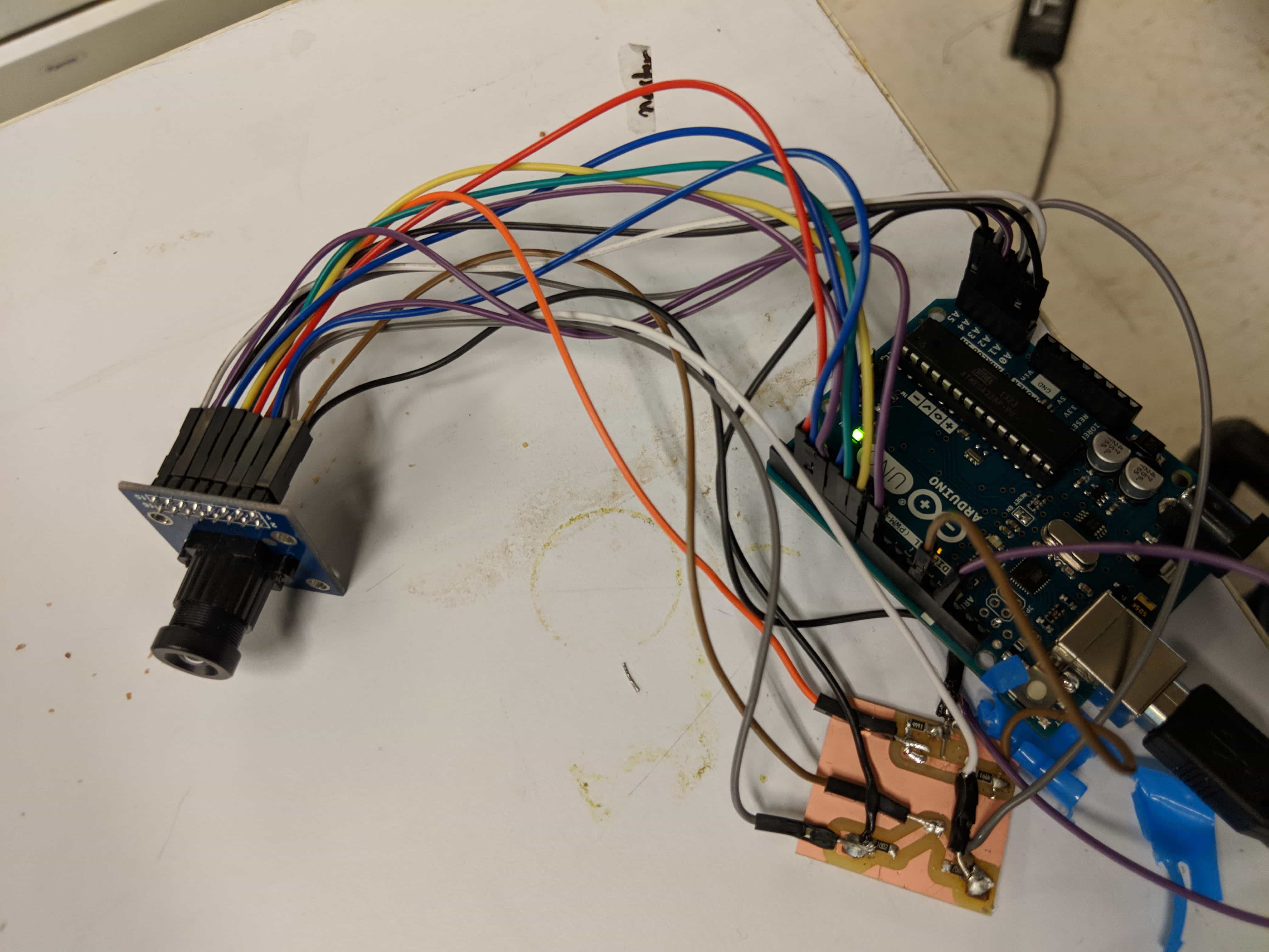
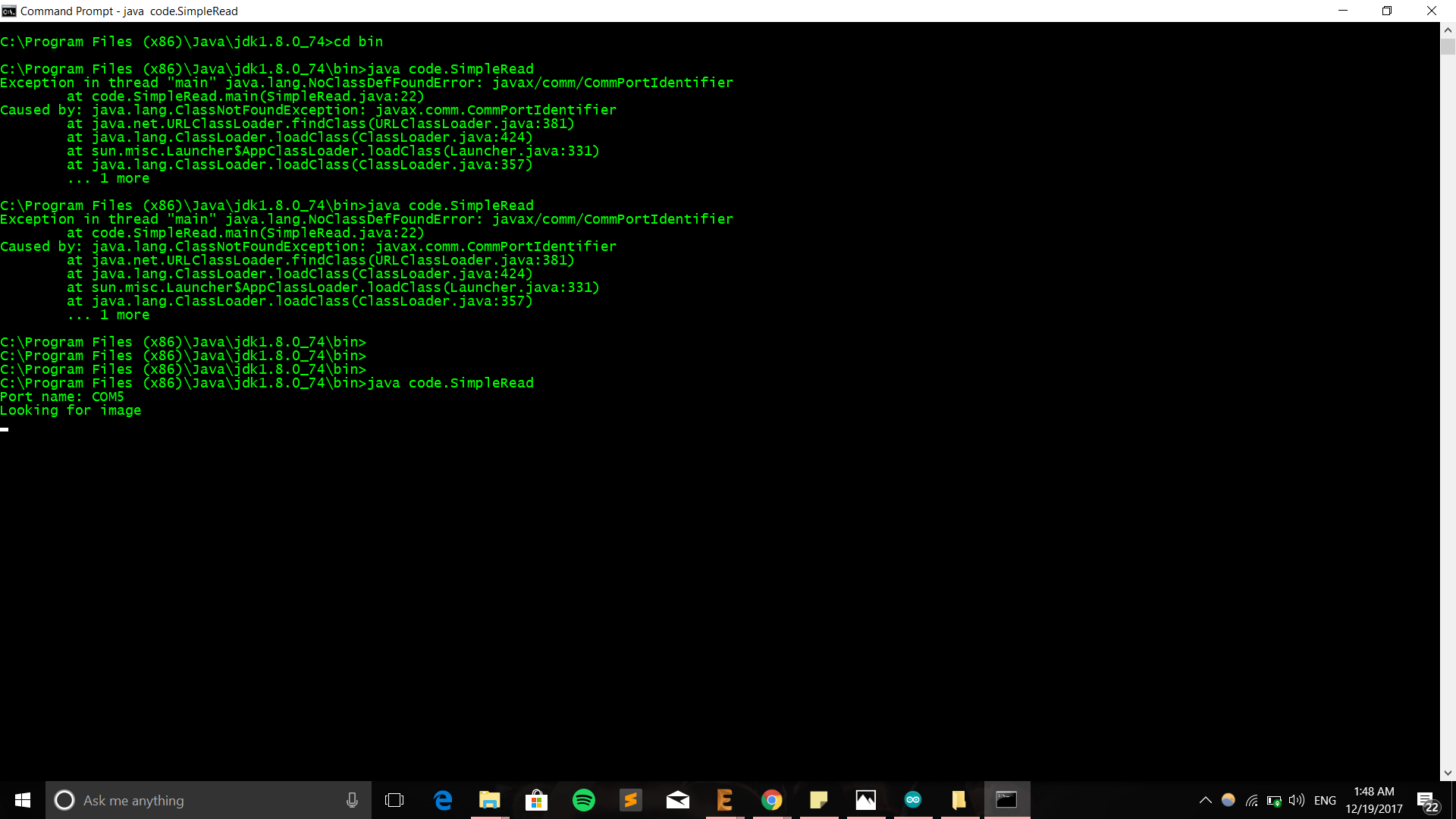
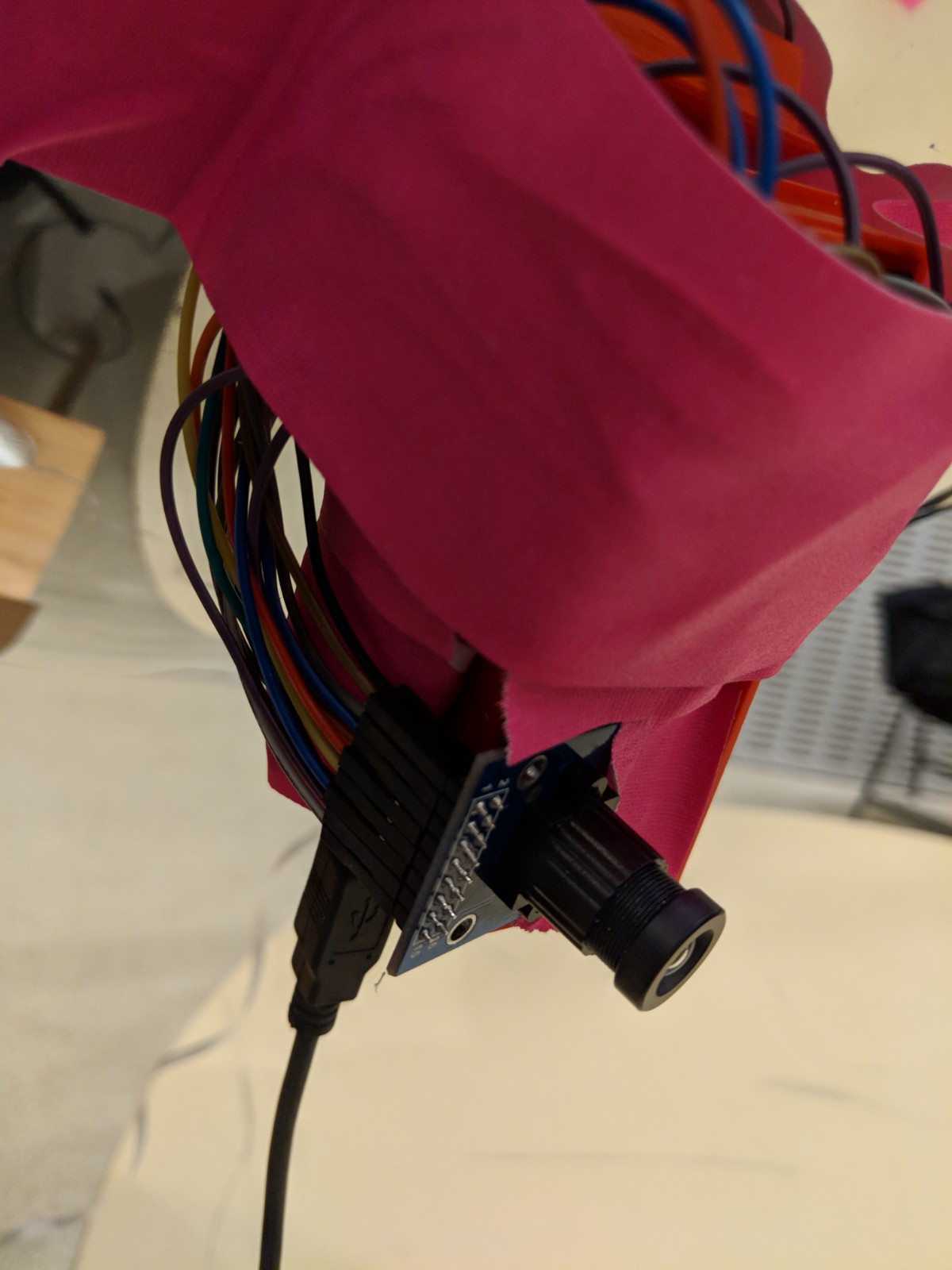
In the end I was able to get Arduino Ide to read the pins and ask the camera for photos.
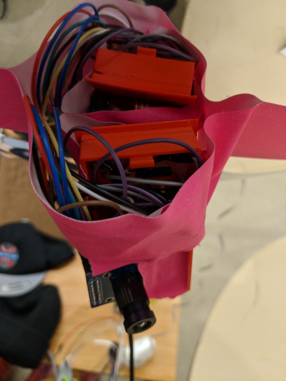
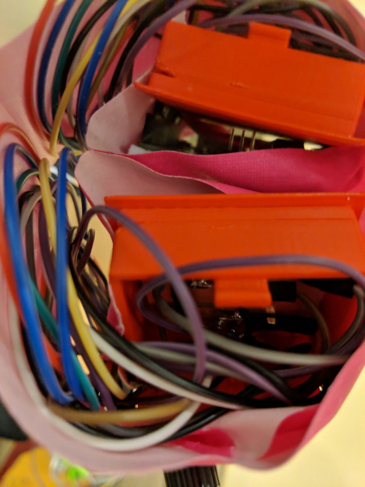
I put this camera in the 3D printed electronics box I made in Week3! Now my girlfriend also has an iconic hat and so I wanted to make that.
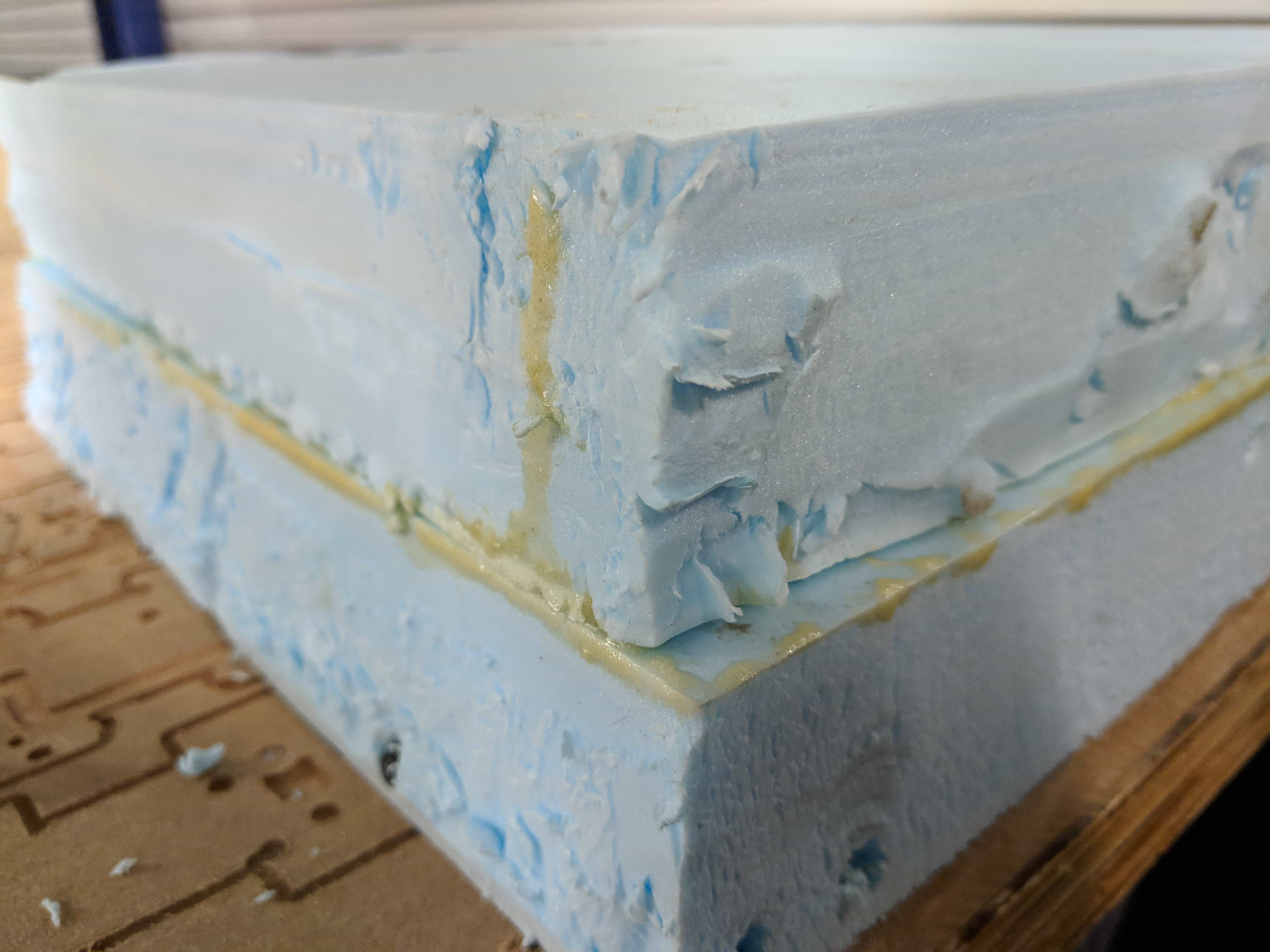
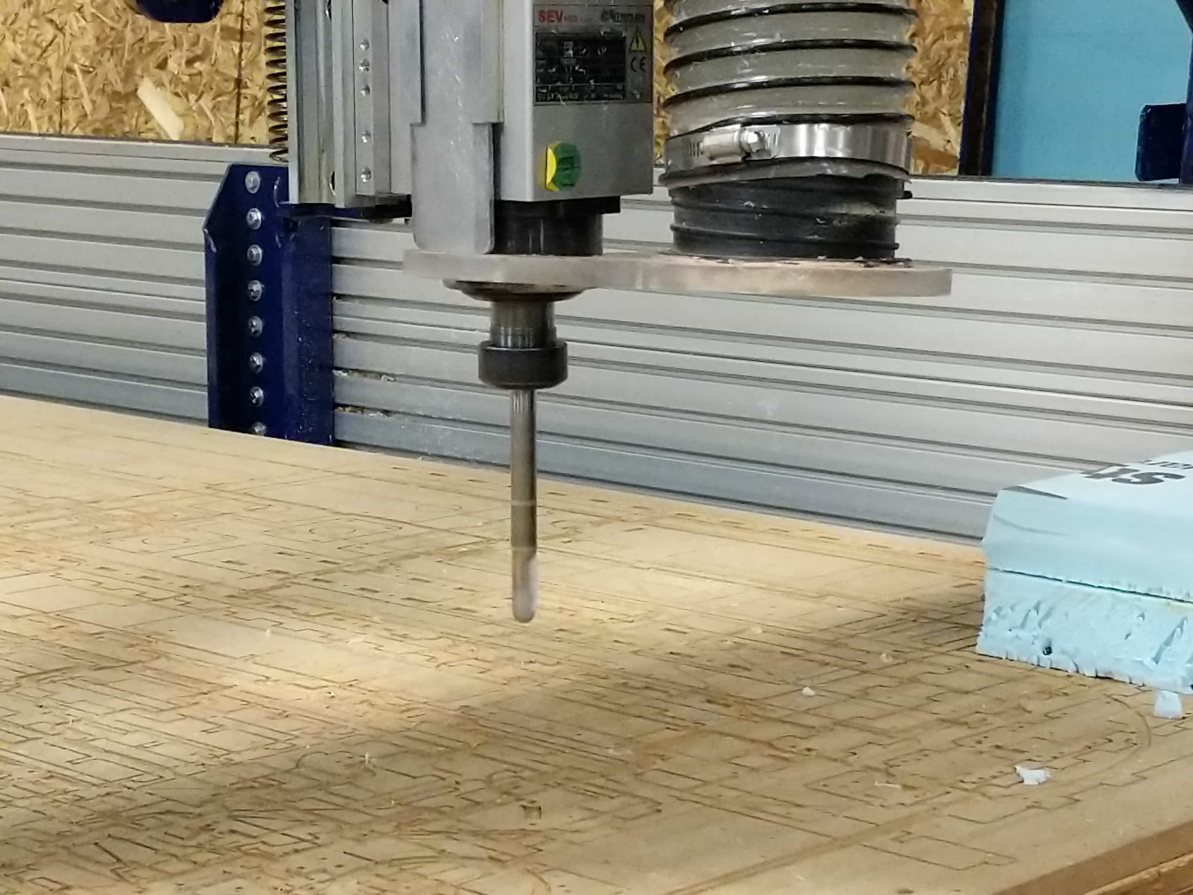
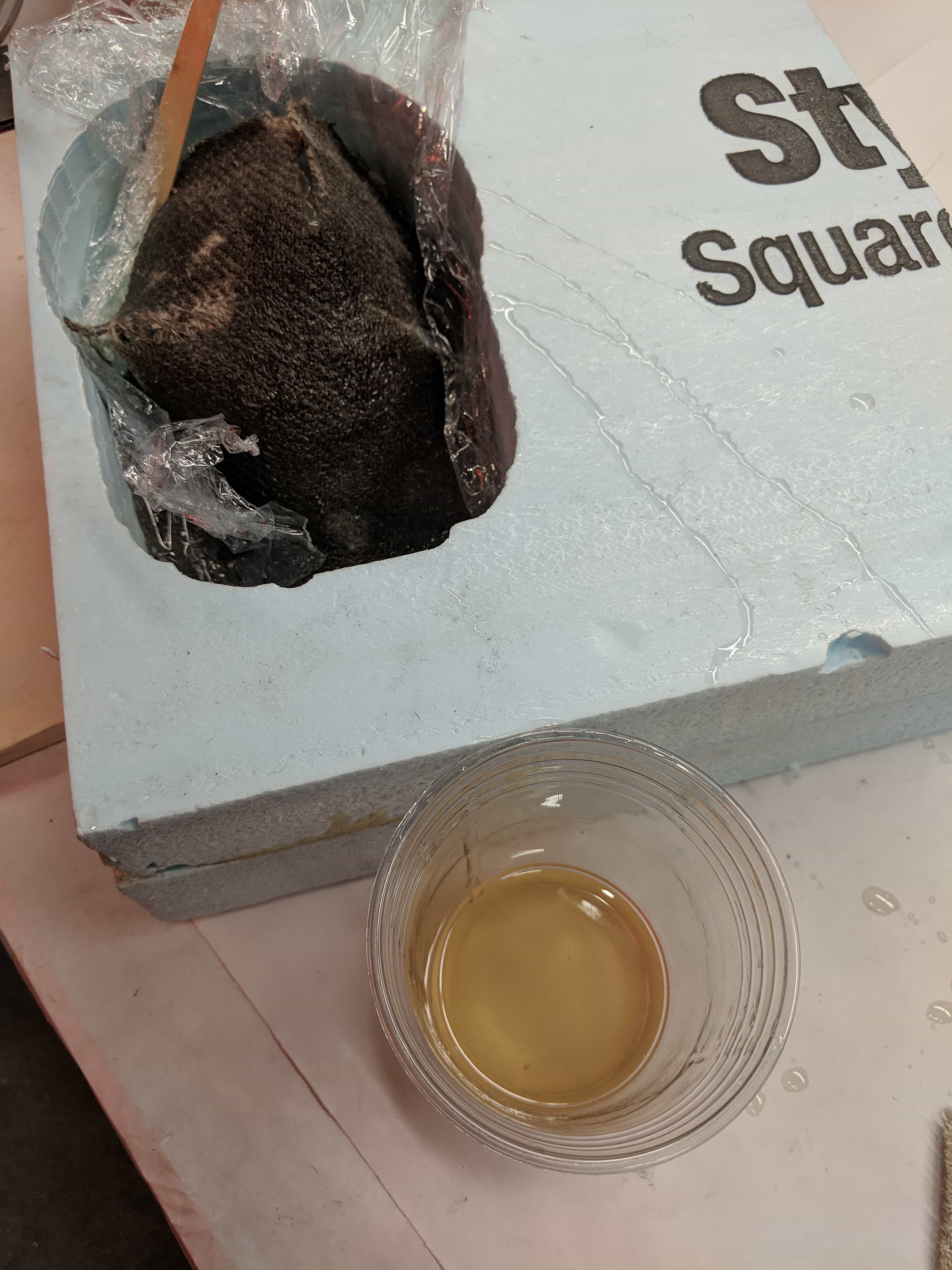
Tom suggested we nail in the foam so it is steady in the bed!
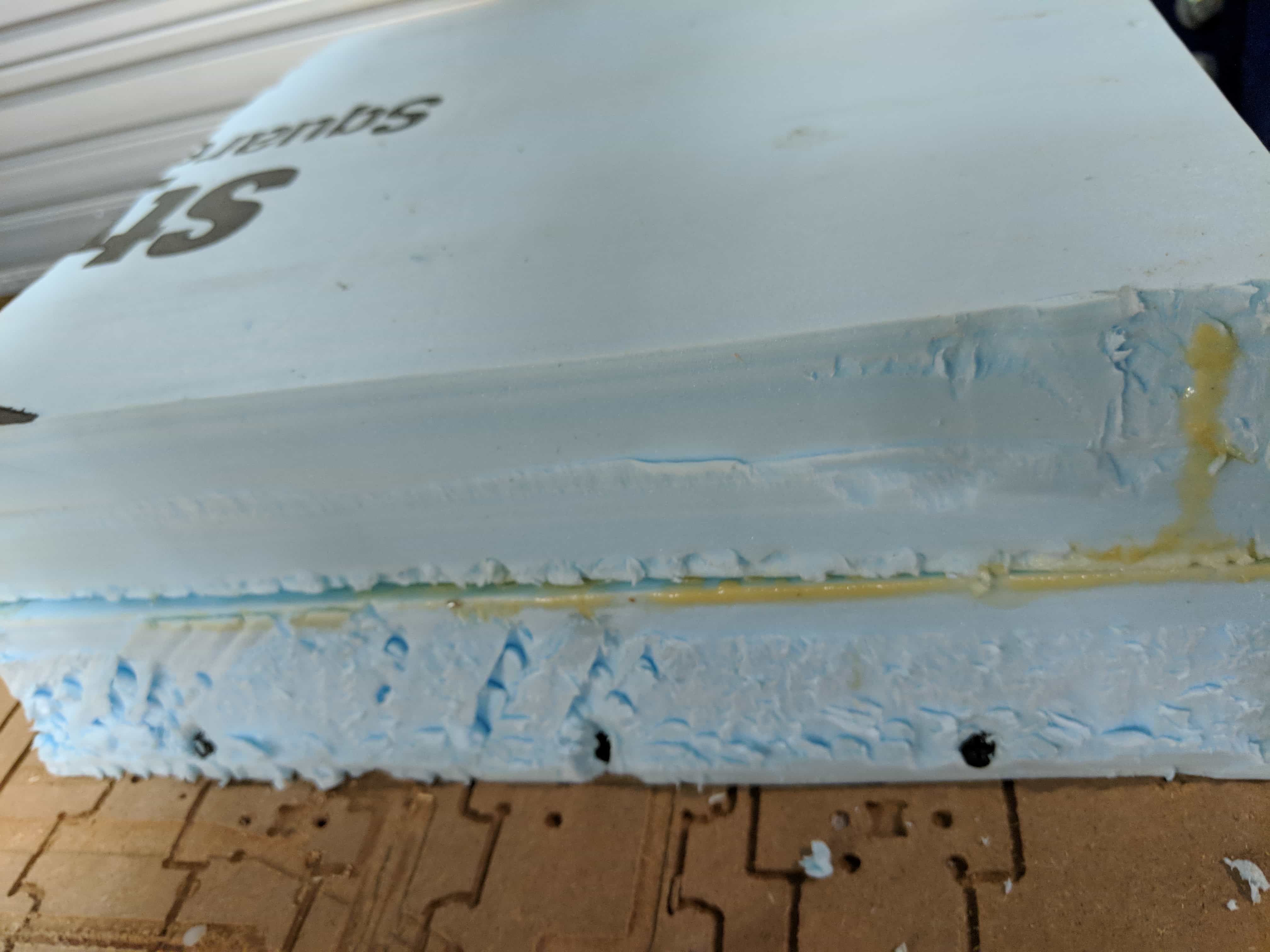
Some of the glue I put into the foam expanded and started to flow down - it was hard by the time it hit the bed of course.
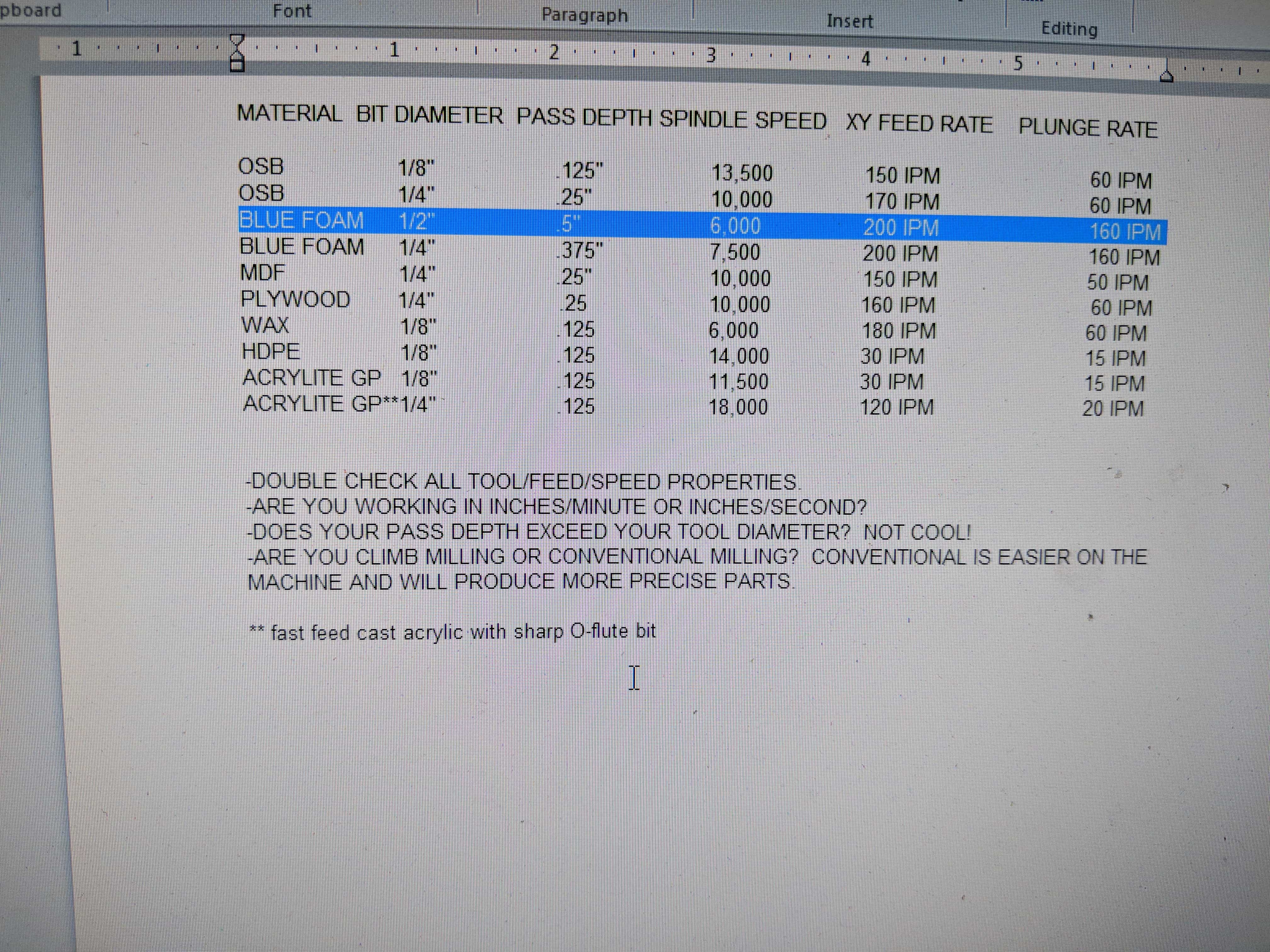
Got to find the right settings!
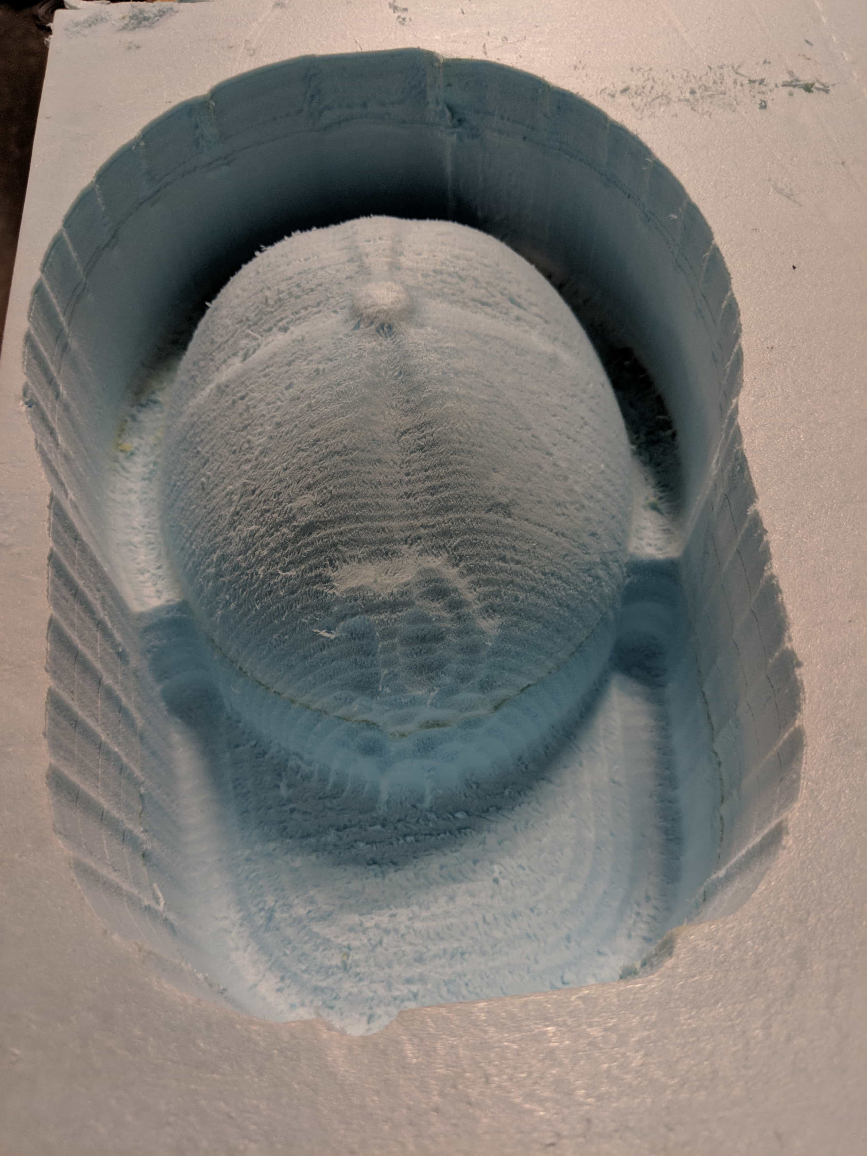
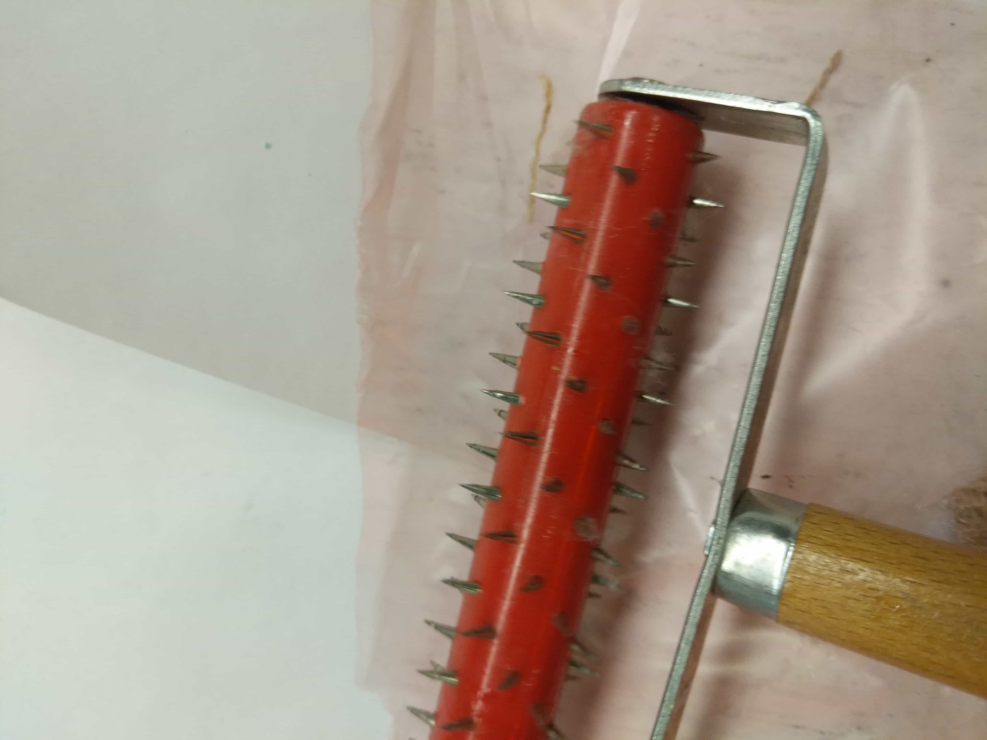
I wanted to see how the baseball cap would come out at this scale! Could I make it more detailed?
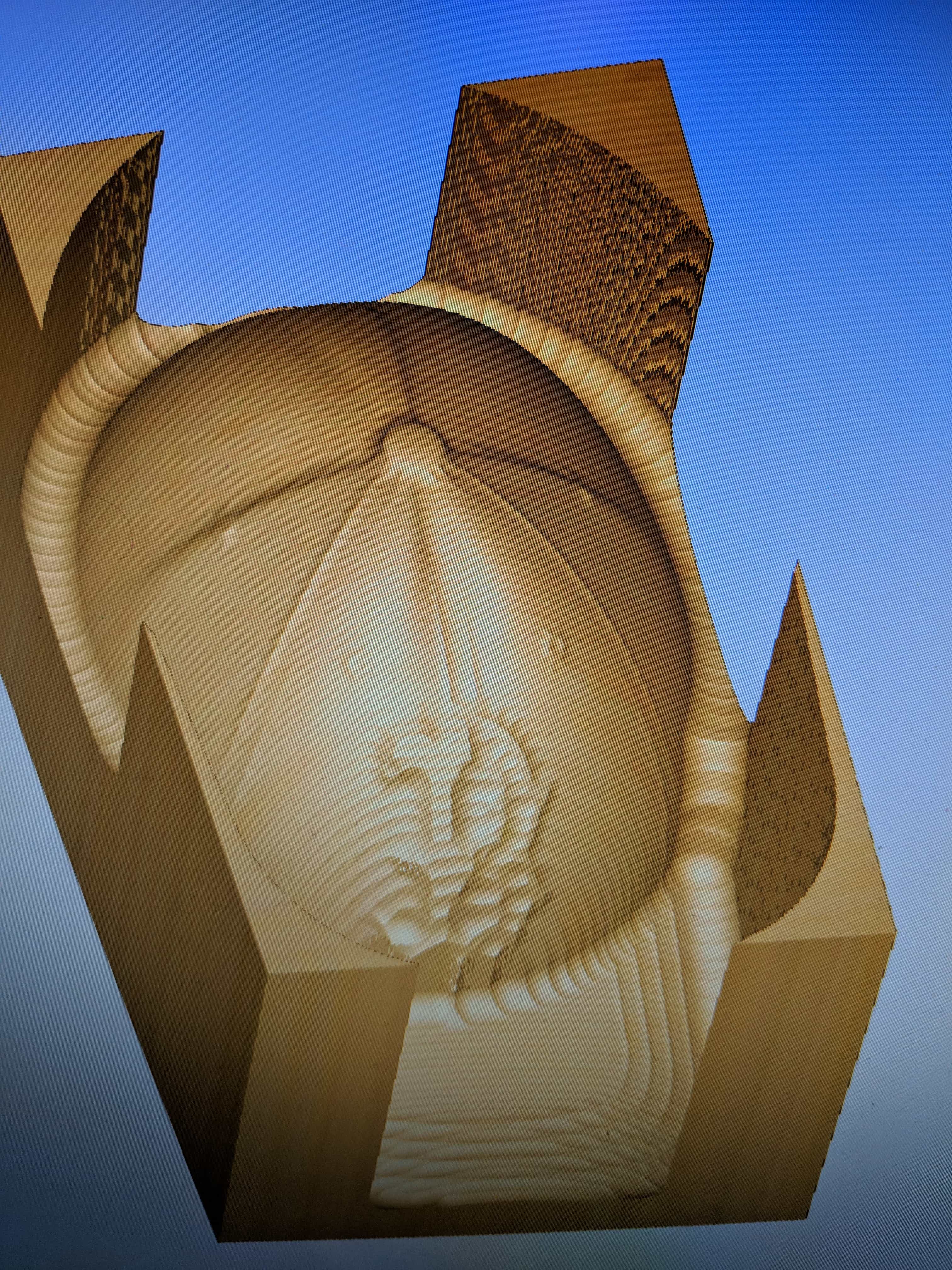
Air runs with the giant drill bit are scary.
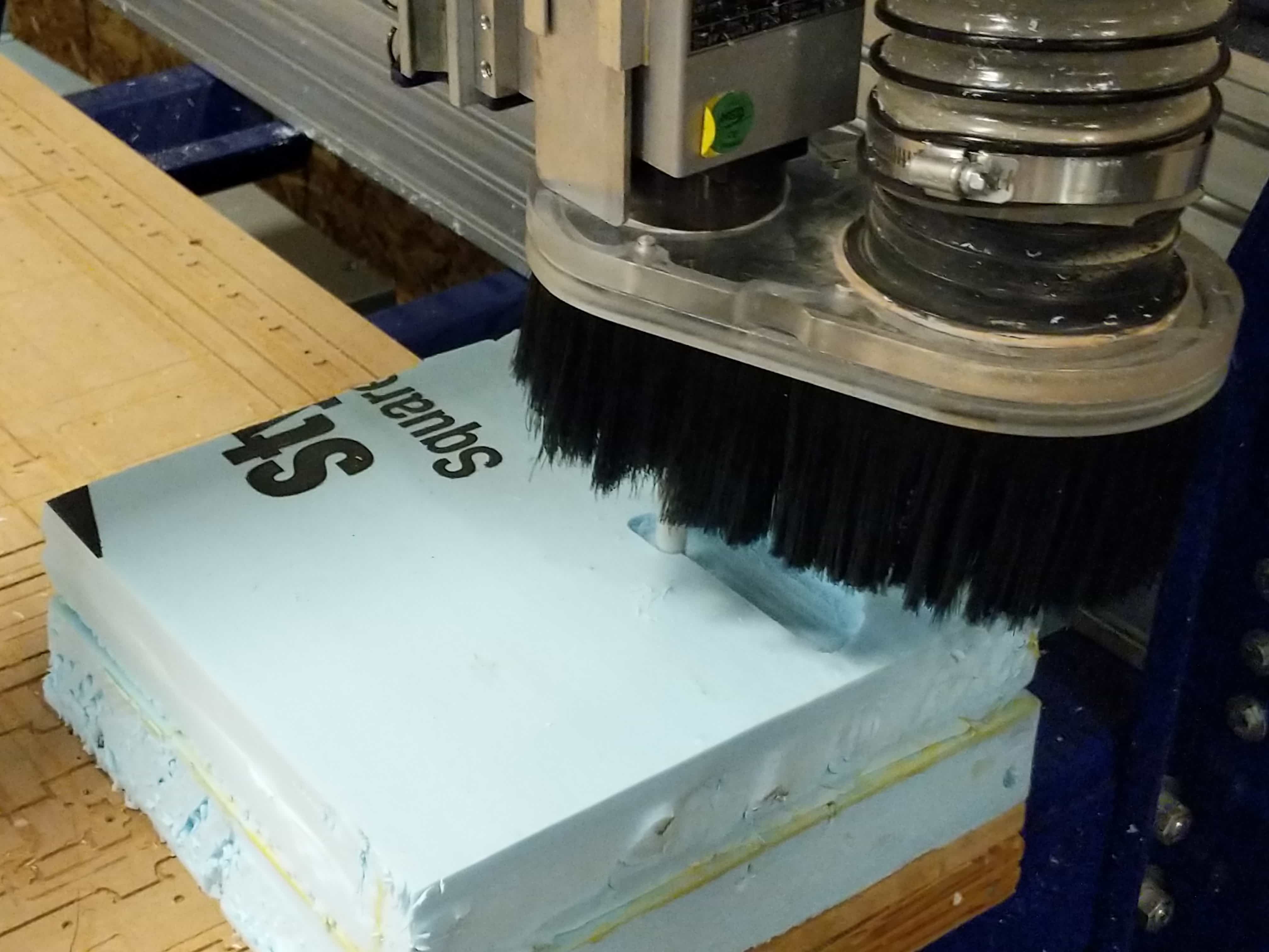
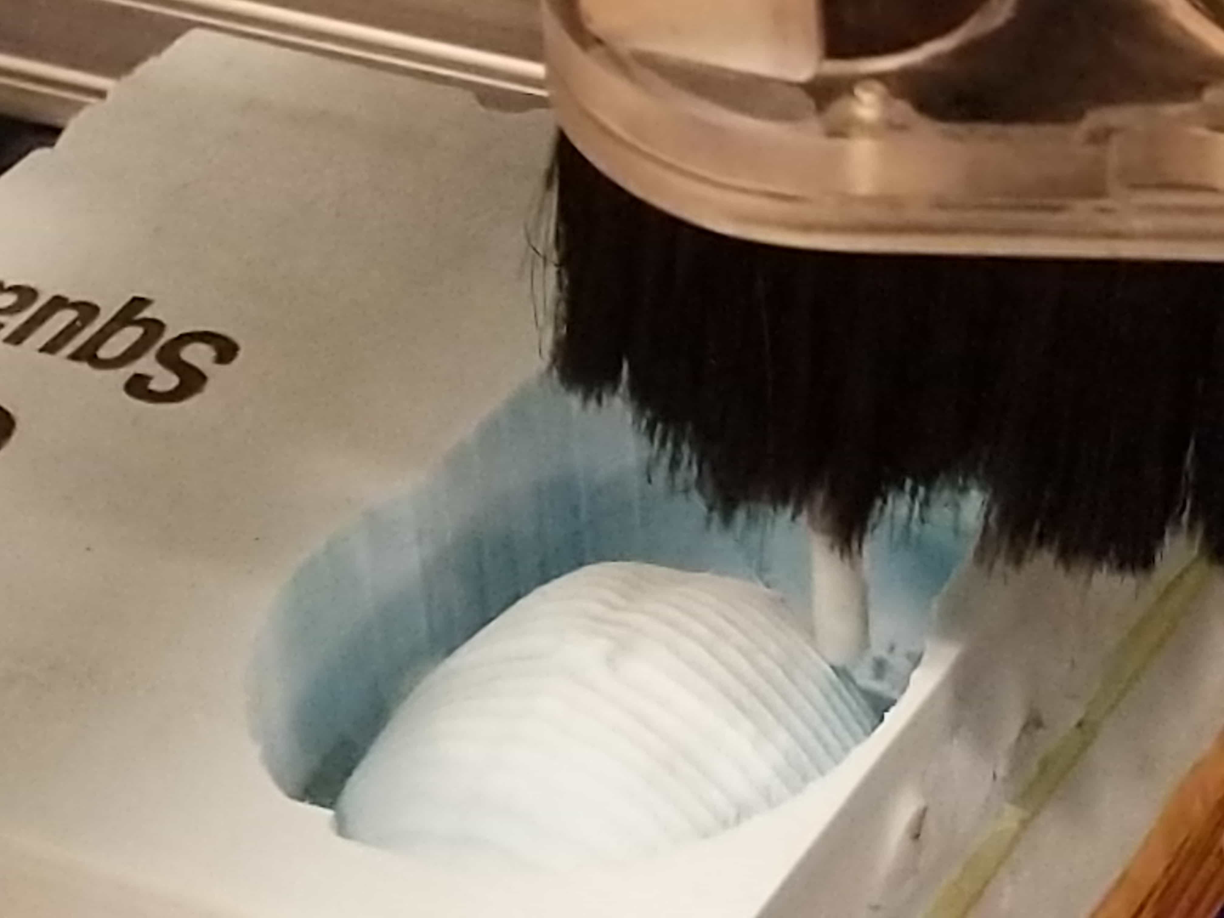
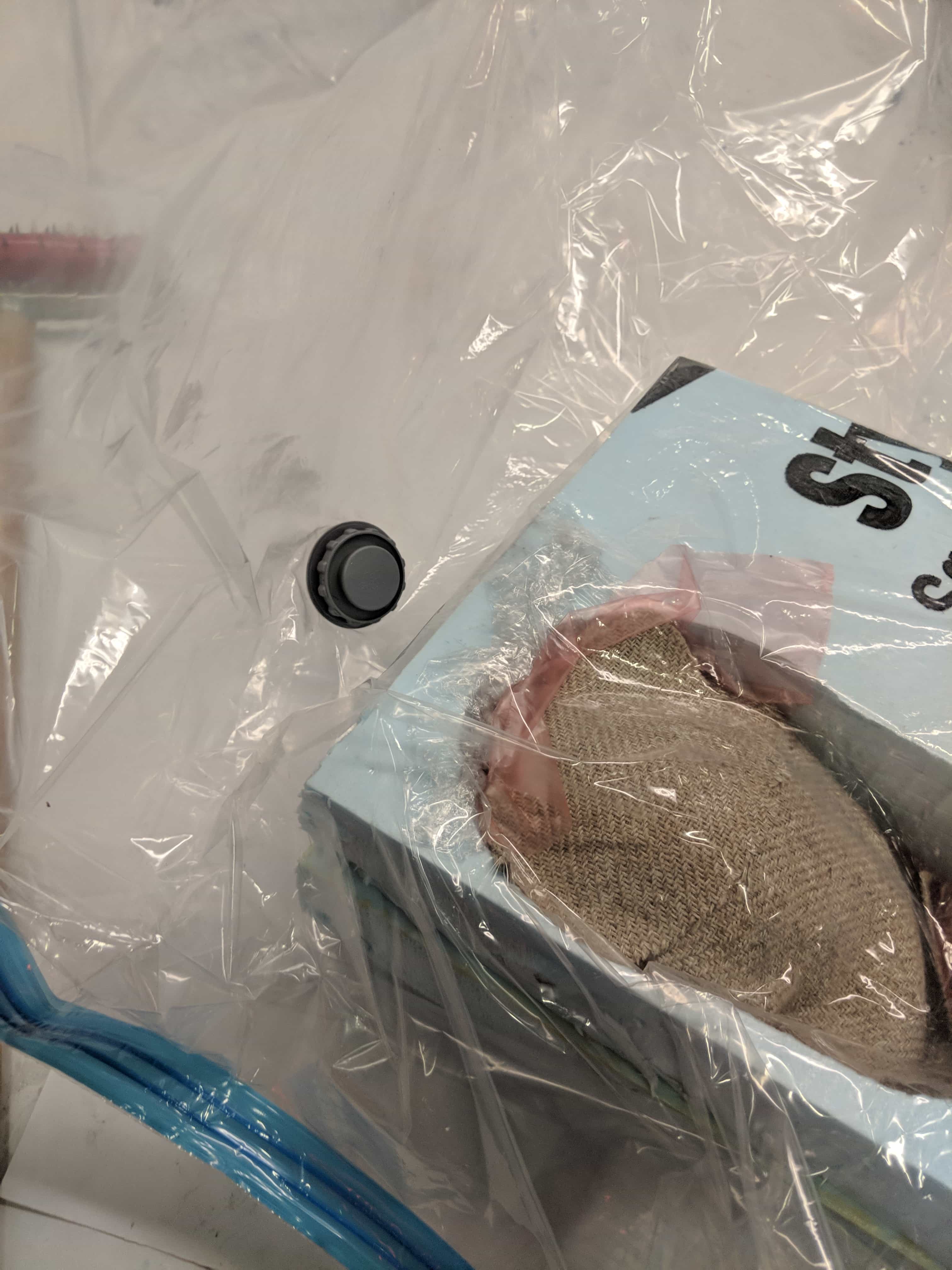
The foam came out pretty nice!
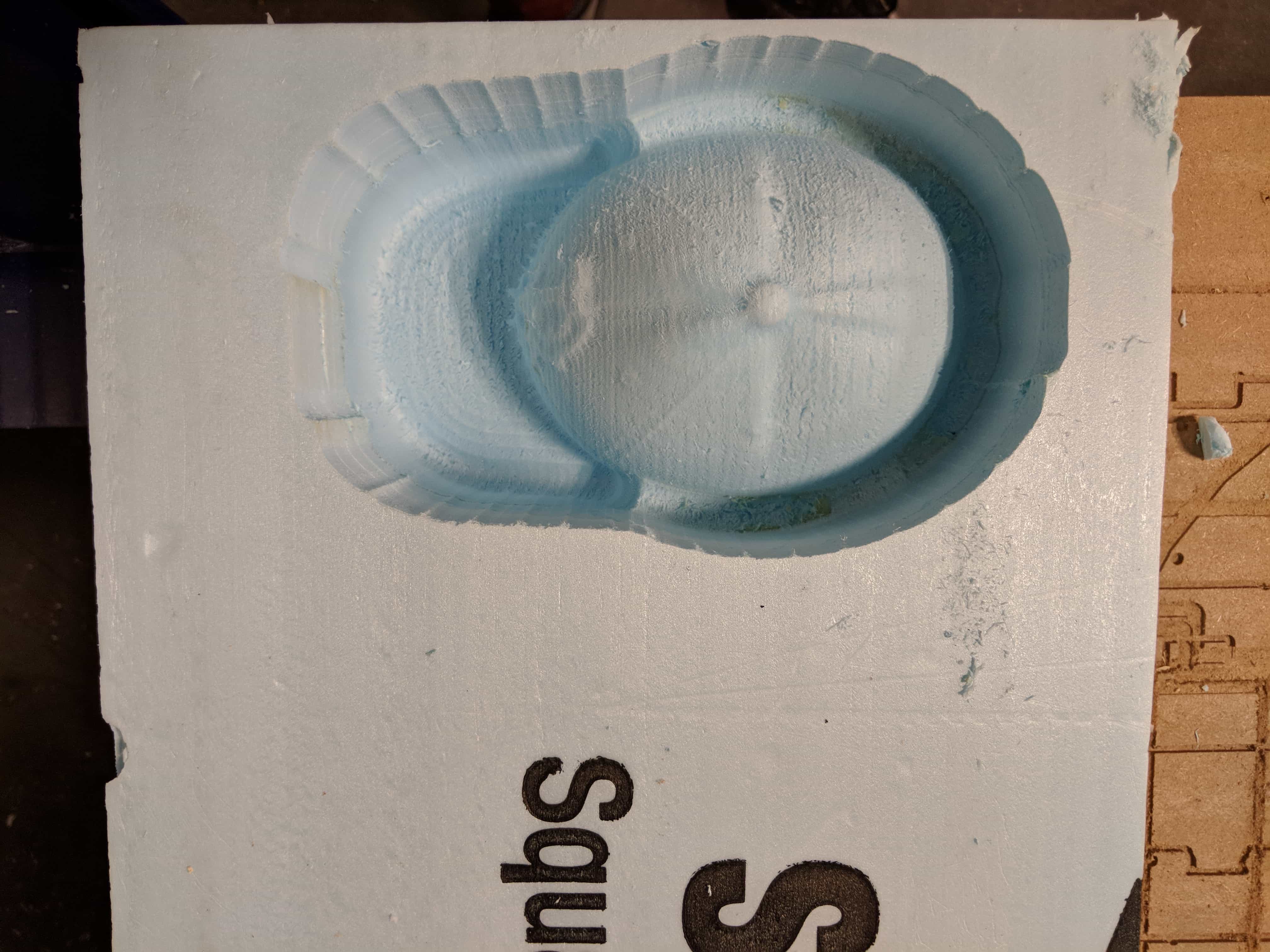
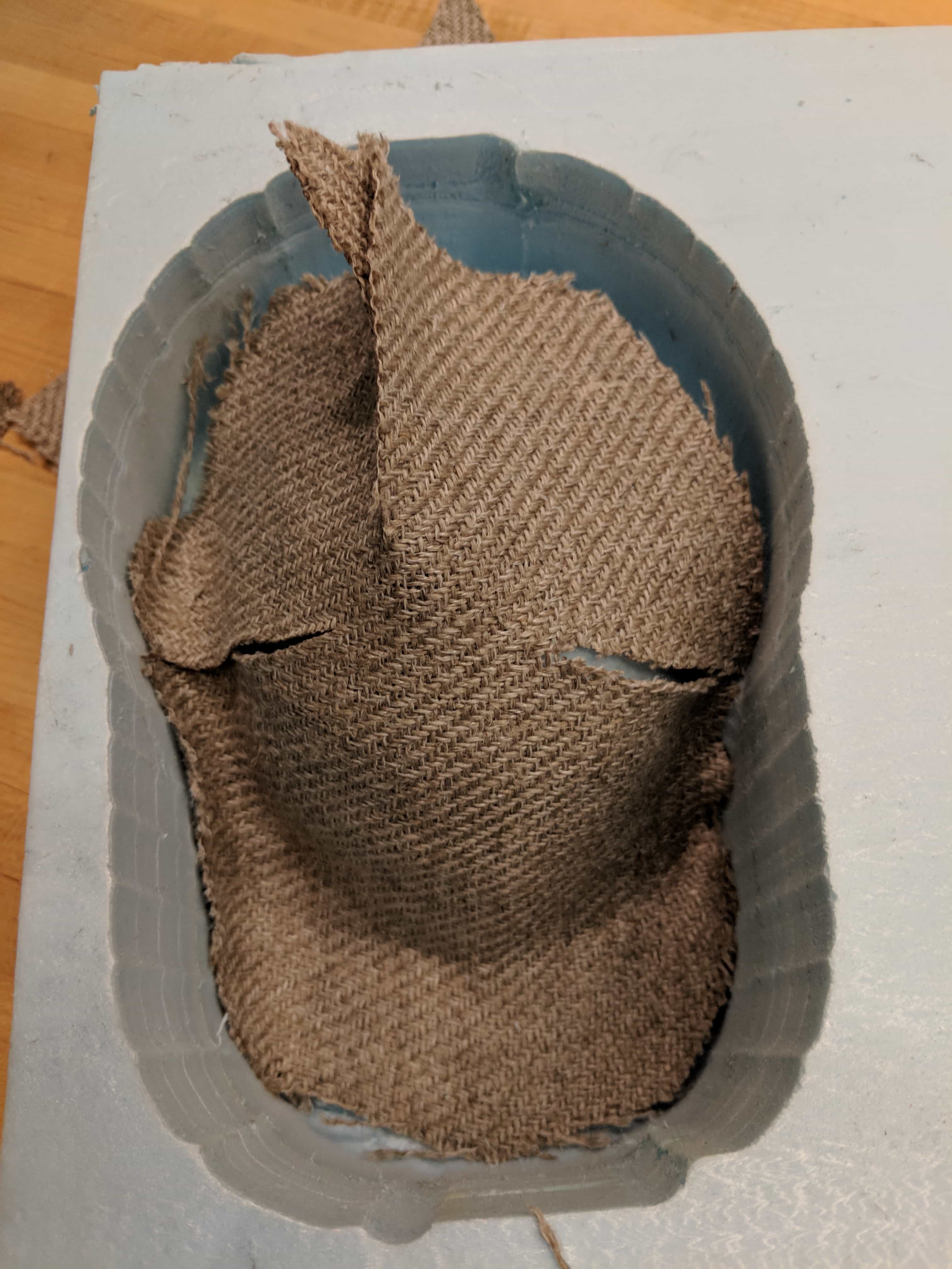
Cut the burlap and laid it over
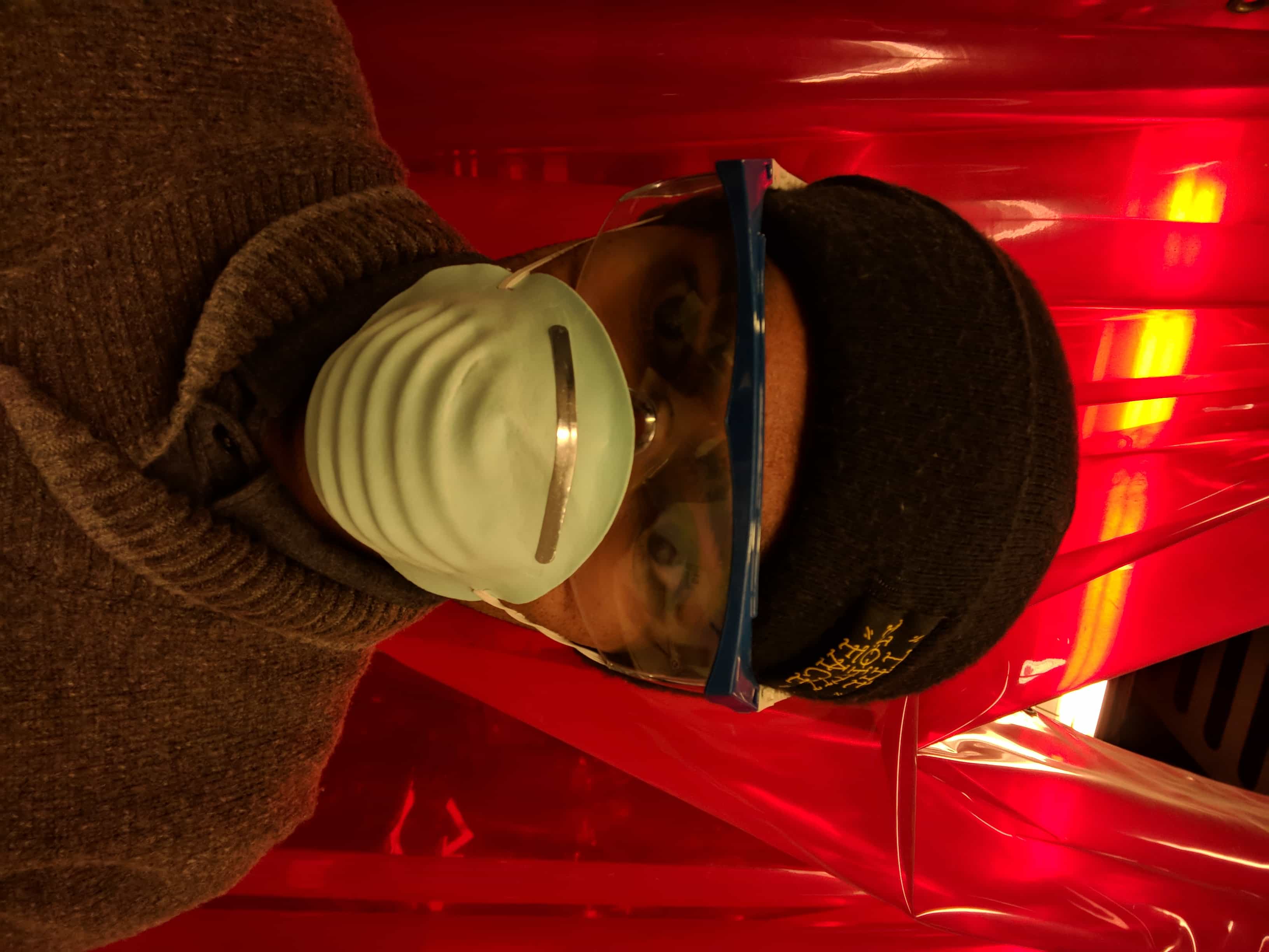
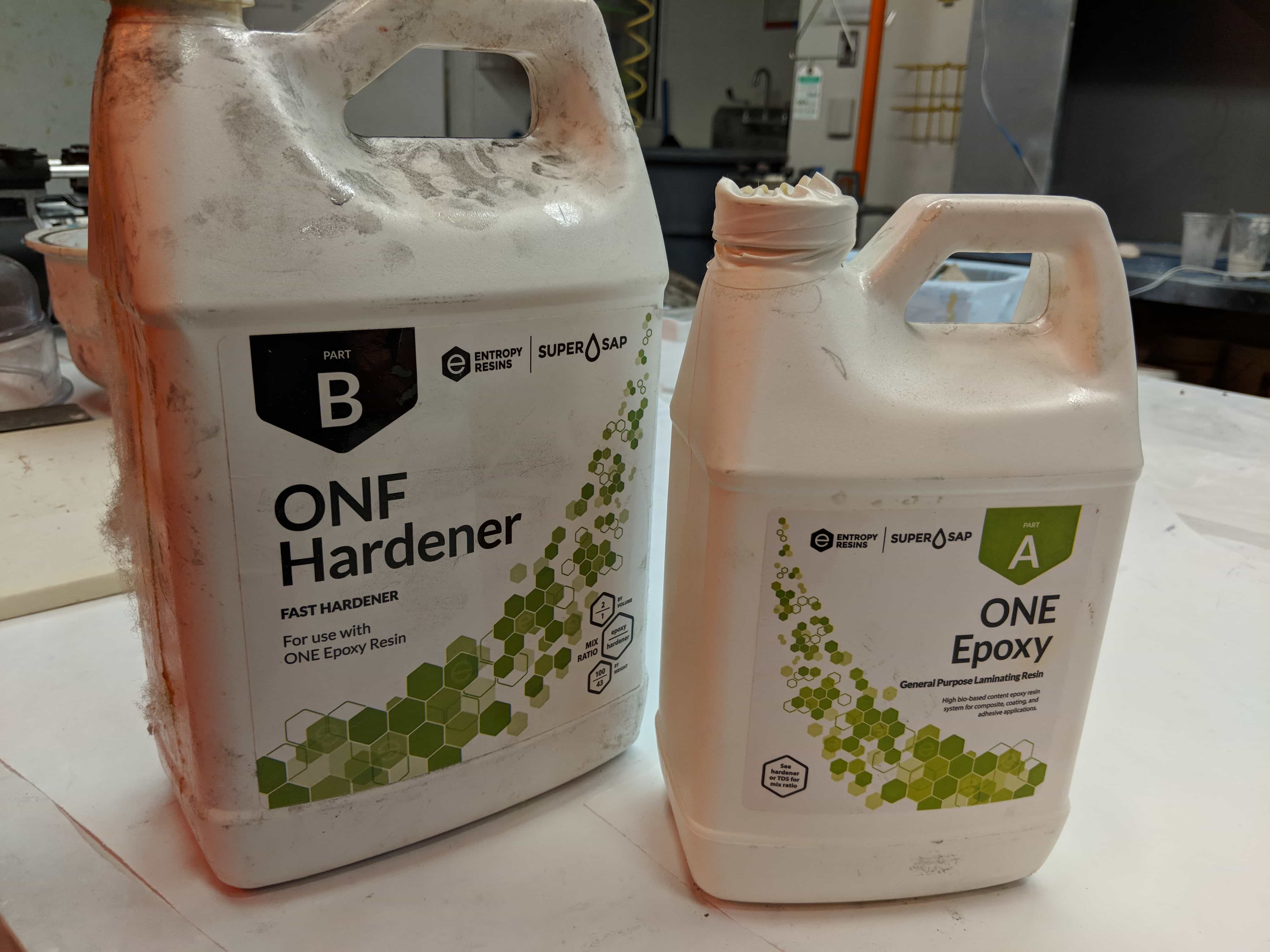
Now time for the epoxy! Safety first.
In the end, after it came out I added hearts to show my loves.
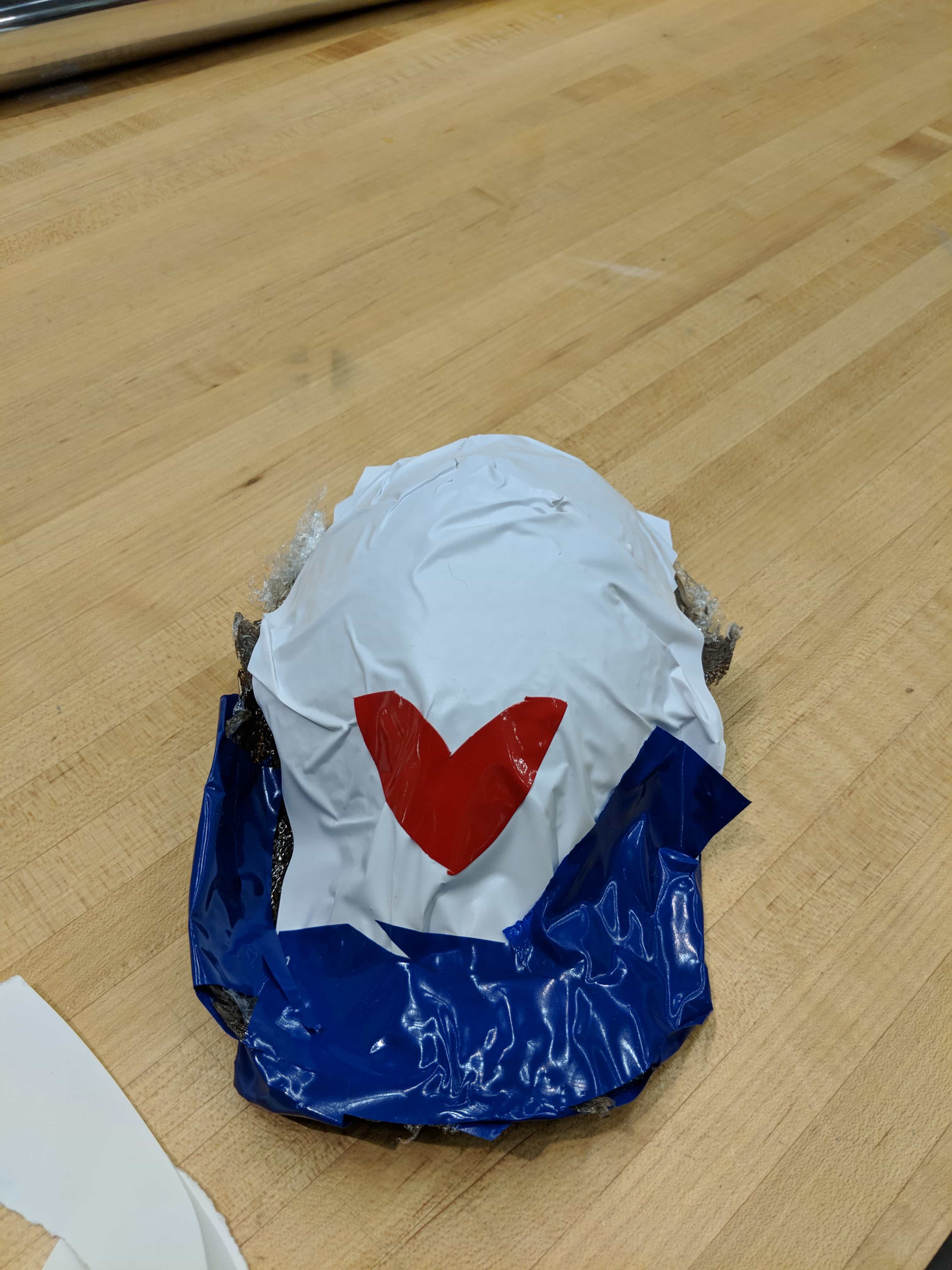
FInally I added some leds to make the entire setup look bueatiful!
Overall, for the project, Balloons are sued with camera and electronics all the time. Most often because they rise they are used for atmospheric photography. At the same time on the ground work is not unheard of. Such as Eytann Mann, http://fab.cba.mit.edu/classes/863.16/section.Architecture/people/Mann/project-15.html, who last year connected a 36’ Helium balloon to a drone.
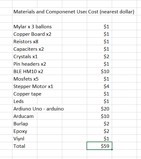
There were five parts to this system: the Mylar ballons (2D Subtractive), the copper tape leds (2D subtractive, electronics design), the camera module (electronics design and production, microcontroller interfacing and programming, 3D design, additive, packaging), the burlap cap (2D subtractive, 3D design), and the stepper turner (electronics design and production, microcontroller interfacing and programming, networking). All of this came together to show what sort of work might be down with balloons on the ground or for one’s significant other. The first is hard in that the balloons were not exactly balanced to float at ground level instead on their own they would have risen – currently they were weighed to ground.
This project was expensive about $60 dollars and was still a proof of concept. I would love to continue developing this project and making a ground level ballonon with a function Bluetooth camera and servo motors.