How To Make (Almost) Anything
Final Project
Introduction
Over the course of the semester, we've been tasked with designing and implementing a final project that combines all the skills we've learned in class. That means our project can't just be in the cloud- it needs to be physical and interactive.
Brainstorming
While ideating on a final project, I can't help but be drawn to toys and interactive experiences. I love designing puzzles that make people happy and help them learn. So, my guiding principle for the brainstorming phase of this project is to create something that would fit in well at the Exploratorium or Epcot's Innoventions Pavilion. I want to create something that users can physically touch and receive feedback from.
Tracks
For our first week's assignment, we were asked to model an idea for our final project in as many ways as possible. I came up with Tracks. It's a toy aimed at children to teach them the fundementals of music composition in an intuitive, physical way. Similar in appearance to train tracks, the kit would come with tracks of different lengths corresponding to rhythmic values (for example, the longest piece would represent a half note, while a track half that length would represent a quarter note). The user would lay down pieces of track and when the train runs over the course, it would play back the notes realtime. There could be multiple cars to represent instrumentation and LEDs on the track would be used to indicate note value (for example, if the track LED was red, it would play the note "C").
Pepper's Ghost Fish Tank
The other idea I'm looking at is an interactive, off-body augmented reality Pepper's ghost (or some other form of projection) fish tank. I got this idea while walking around the New England Aquarium. The lighting conditions in the building are nearly perfect for reflecting a light source into the tank. That could be used to convey information about the residents of the tank, create immersive, generative media to interact with the fish, or create a platform for users to play with the fish. For example, if you track the fish's location/type, you could put a digital bounding box around the fish, displaying information about that fish when a user presses the corresponding button. With the fish's location, you could also have it interact with digital media in the tank. For example, if it swims past the physical volcano prop, digital lava could flow. Lastly, users could draw with the fish. If they press the draw button, a trail could follow the fish around the tank showing how the fish moves accross the space.
TRAX
what is it?/what does it do?
Trax is an interactive, musical train track. Using the button pads, toggle between RED, YELLOW, GREEN, CYAN, BLUE, PURPLE, and WHITE to change the note value. Reorient the tracks to change the note durations. Slide the train over the track to trigger a note. Move at a steady tempo to dictate rhythmic accuracy or freestyle it by scratching the train or a bright light across the surface.
who's done what beforehand?
I was inspired by several color/sound interactive interfaces. Those include, specdrums, audible color, looks like music, and kandinsky. Additionally, I used toy wooden train track dimensions as reference for my tracks. Interestingly enough, apparently every toy train kit manufacturer develops slightly different groove heights and connections from the competition to avoid patent infringement. Lastly, I took direct inspiration from Little Bits. I wanted to create a network of physically connect devices and enable them to communicate back to my computer when connected.
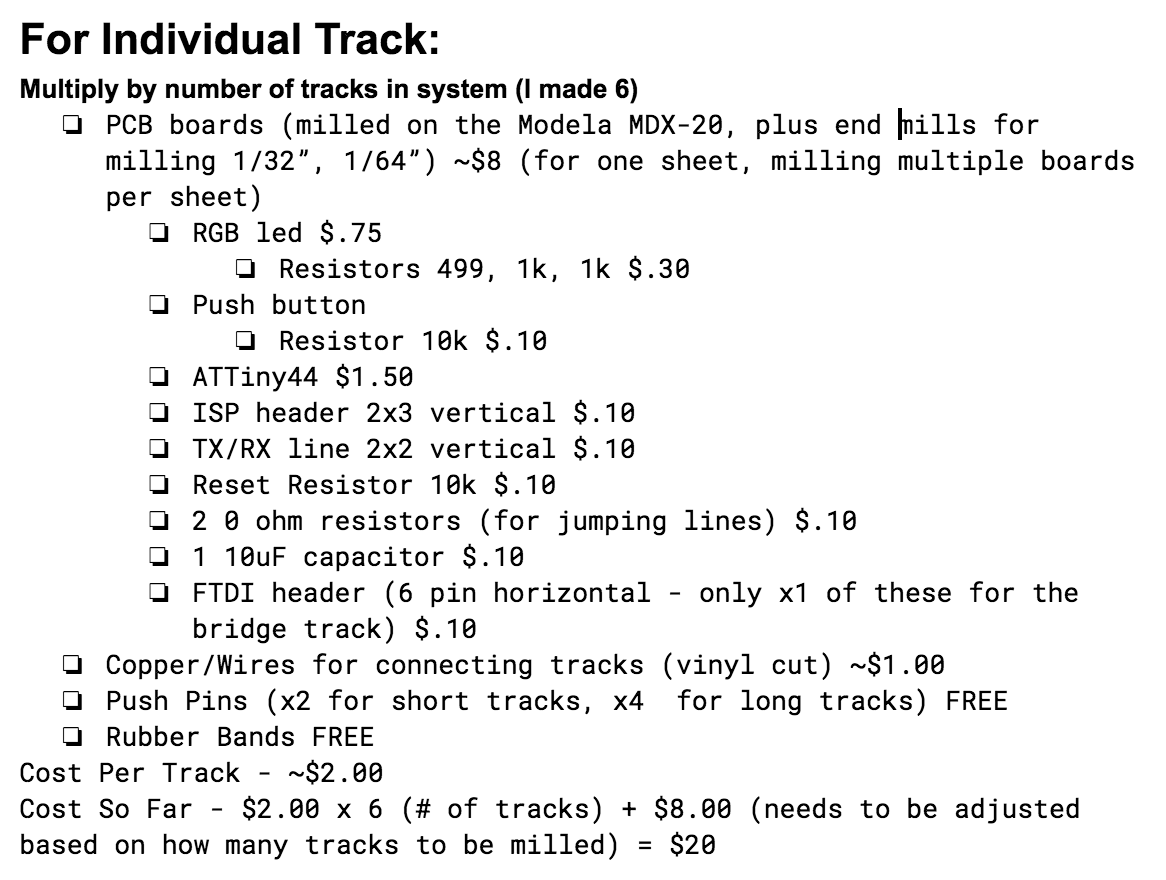
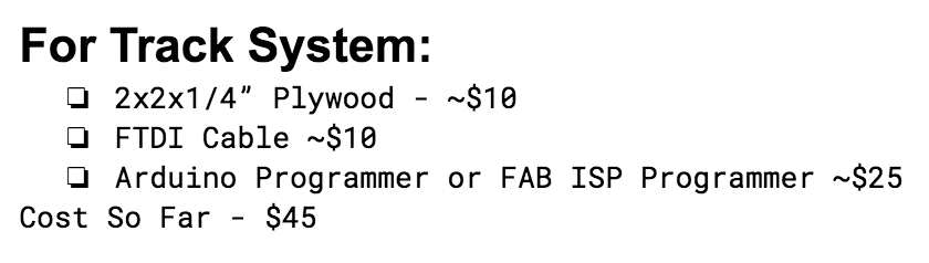
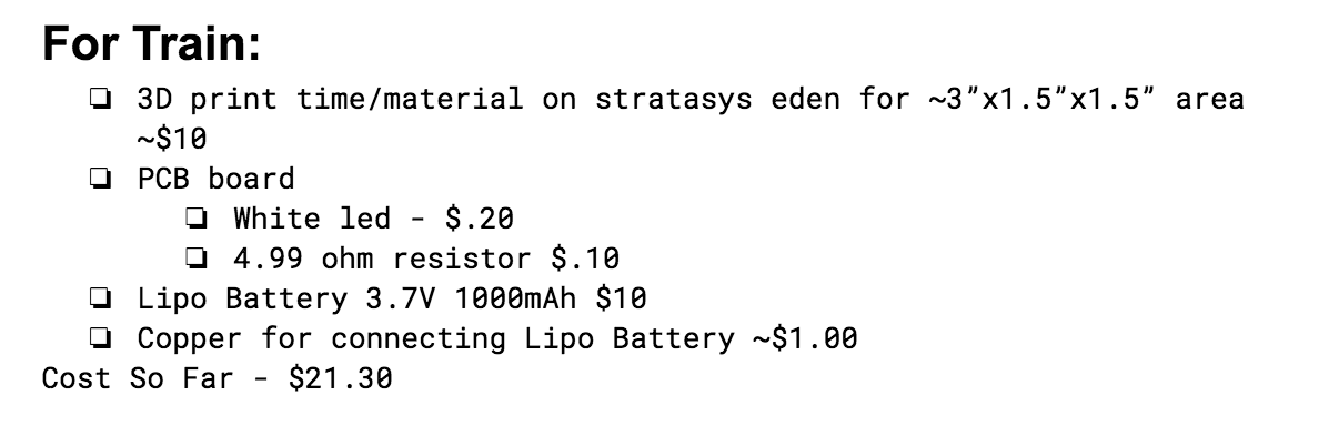
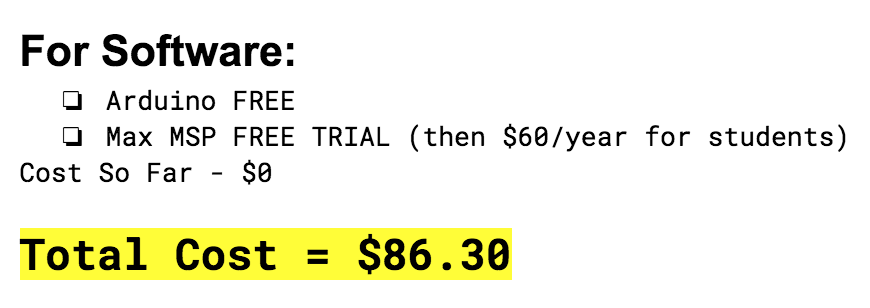
bill of materials
design
Fabrication
Train
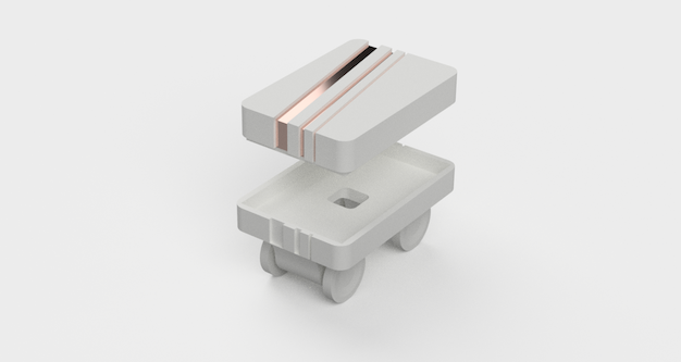
Figure 1: Rendering of Train Design
For the train, I wanted to make my components all in one piece. That means that when I printed out the train, I wanted the wheels to already be embedded in the axis and ready to turn. Additionally, I wanted the train to contain a small circuit with a white LED and lipo battery inside. I vinyl cut copper traces to fit around the hood of the train, so when you open the lid, the battery is off, and when you close the lid, the battery is on.
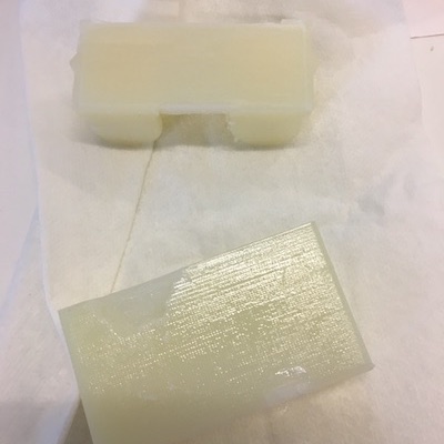
Figure 2: 3D print of thingaverse train
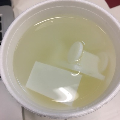
Figure 3: Dissolving the support material
To do this, I started by printing a ready-to-go model train I found on thing-a-verse. That was useful to measure tolerances and such. Once I was confident that I could create my own design to be printed on the stratasys, I went to work in eagle. I wanted to be able to fit the battery and the circuit, but otherwise, keep my train low profile. I added grooves into the top of my lid, so I could embed vinyl cut copper to turn the lid into a switch for my battery. I even designed the grooves so they'd have a proper orientaiton (not that that would stop me from burning the f*ck out of my fingers putting the lid on backwards).
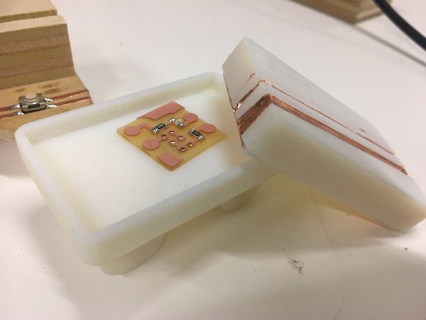
Figure 4: Final Train Design
Tracks
I decided early on that I wanted to create my tracks out of wood using the shop bot. I looked up the measurements for standard track sizes and Tom was kind enough to give me a piece of plywood that was nicer than the OSB we previously used with the shopbot. I originally intended to have track pieces on top of the bottom communication line piece, but time/integration got the best of me. I milled the traces on the shopbot using a 1/8" flat down endmill. Once I created pockets for each of the shapes (1/2" deep for the electronics housing, and 1/4" deep for the grooves), I turned off the vacuum as I didn't want my track pieces to get sucked away from the bed. After I cleaned the bed of shavings, I sanded the wood to remove the small burrs that had appeared on the edges. Additionally, I had created some longer pieces, that I intended to represent half notes. I ended up not using that track piece in my final implementation.
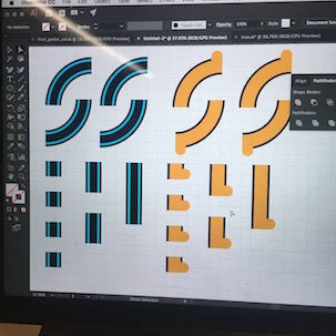
Figure 5: Early Train Track Design
There are two different track lengths. The longer track piece is twice as long as the shorter piece, which gives the timings of a quarter note and an eighth note. Additionally, I had created curved pieces that would've allowed for loops, but I still need to work out the tolerences on those.
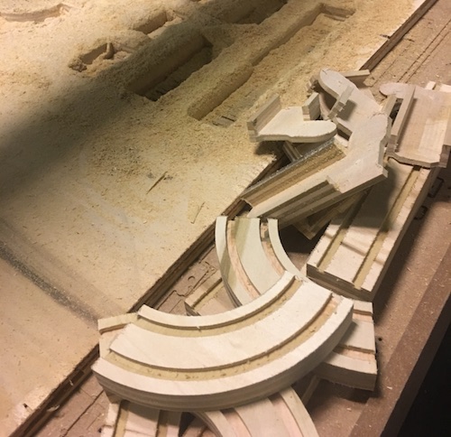
Figure 6: Milled Track Pieces
Electronics
Train PCB Design
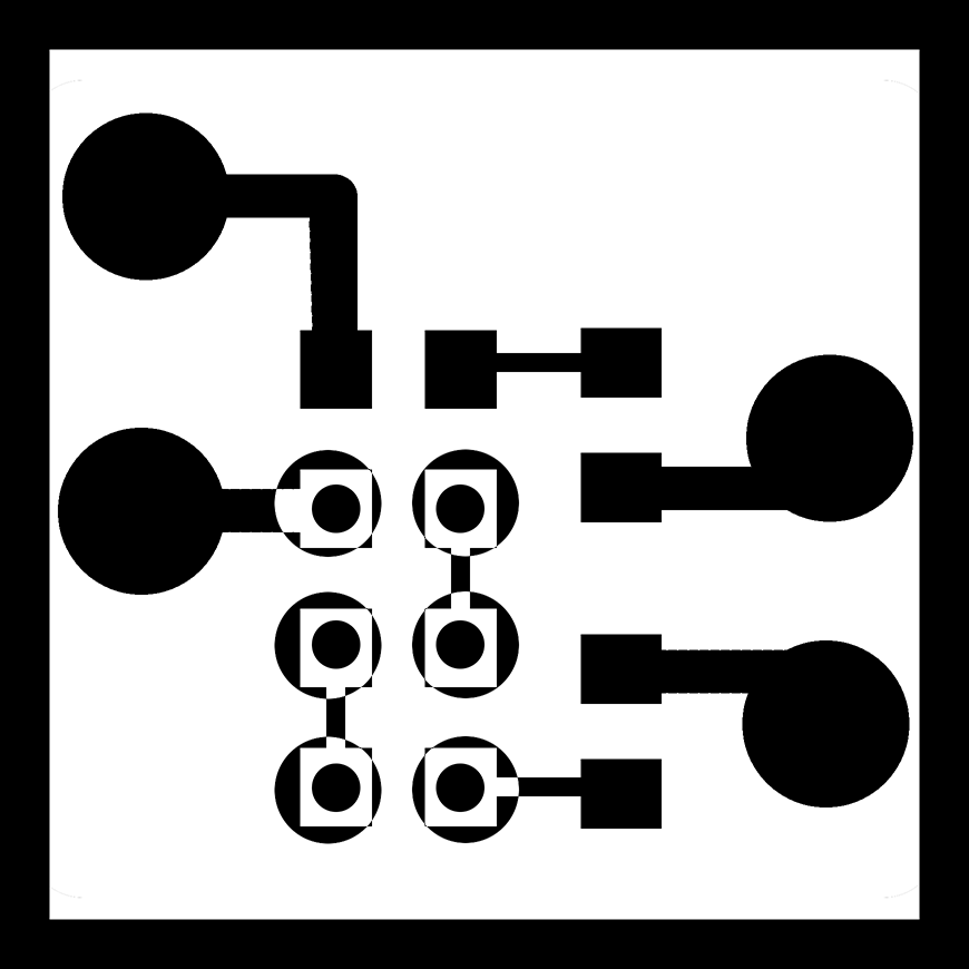
Figure 7: Train Circuit
Figure 8: Electrical Components of the Train
I designed the train to fit a 3.7V 1000mA lipo battery and the board for my light to shine through to trigger the phototransistor on my track boards. Originally, I had intended to use IR phototransistors for this project, but I couldn't verify the wavelength of the IR phototransistor and it wasn't responding to my IR LEDs (which, according to the packaging were in the 940nm wavelength to match the phototransistor). I was sure my LEDs were working because there was a voltage drop of ~1.2V between each LED. When I switched out the IR LEDs for the white LED, I could only use one because of the power requirements. This is totally fine because the white LED is super duper bright. My visible spectrum phototransistor worked perfectly with my track board and the train, which leads me to believe that the either the IR LEDs or the IR phototransistor were labeled with the incorrect wavelength. Additionally, I designed copper vinyl cut traces to loop around the hood of the board, so the lid would act as a switch for the lipo battery. (PS, don't short lipo batteries while holding your fingers on the copper. It doesn't feel good.)
Track PCB Design
Figure 9: Eagle Layout (early board design)
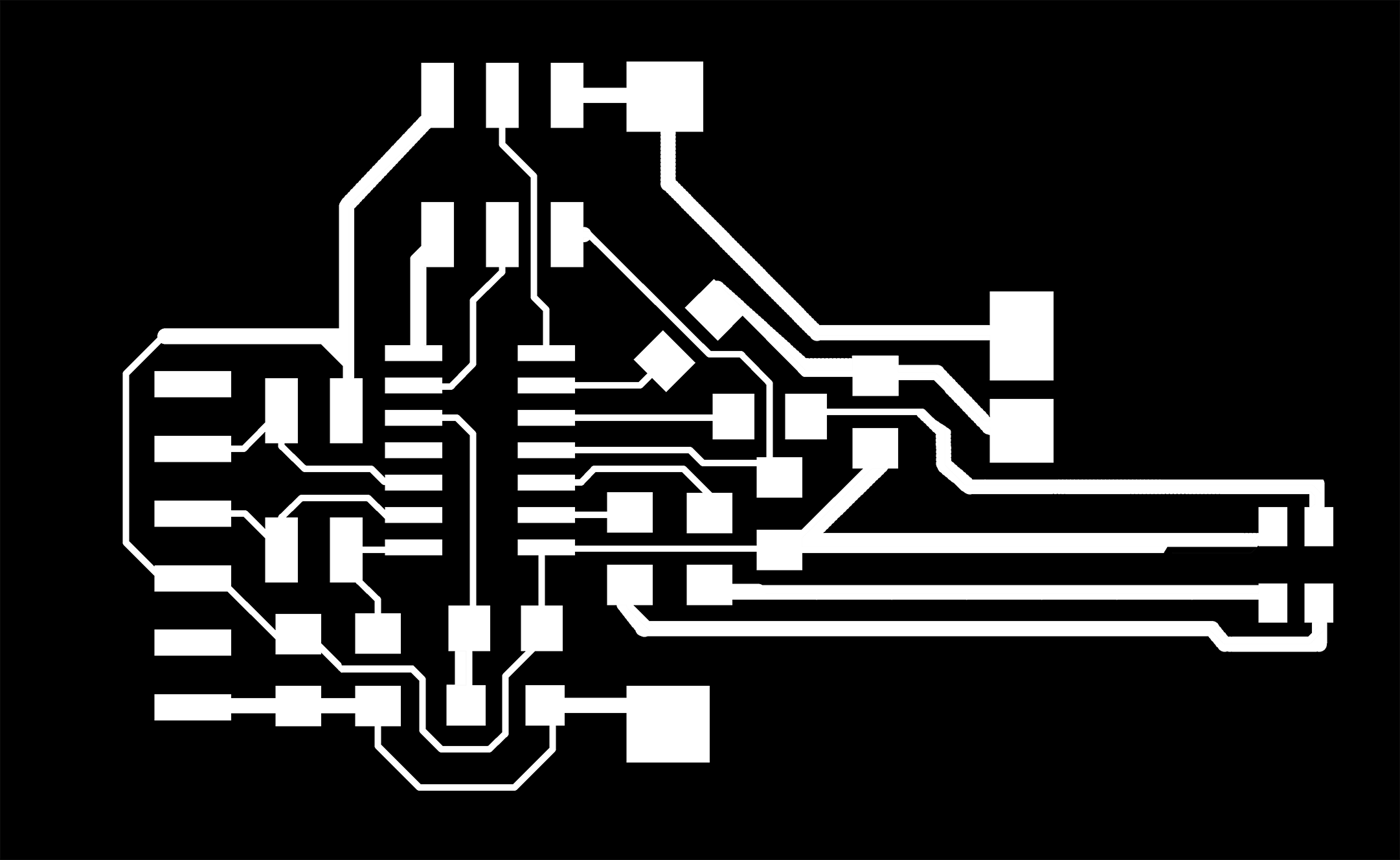
Figure 10: Serial Connect Node Traces
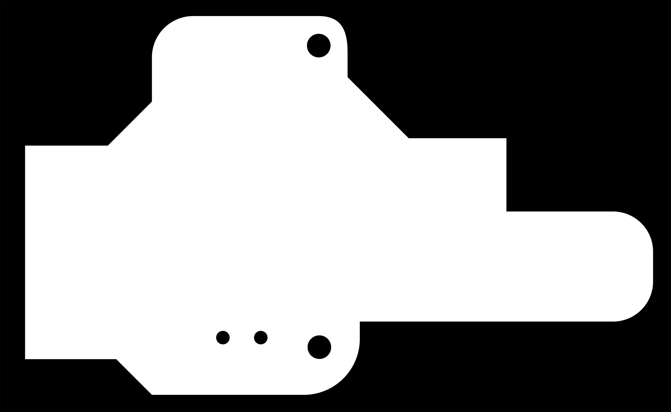
Figure 11: Serial Connect Node Cut
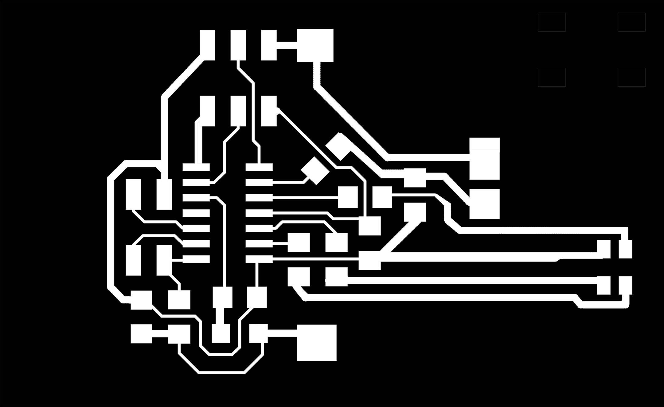
Figure 12: Child Node Traces
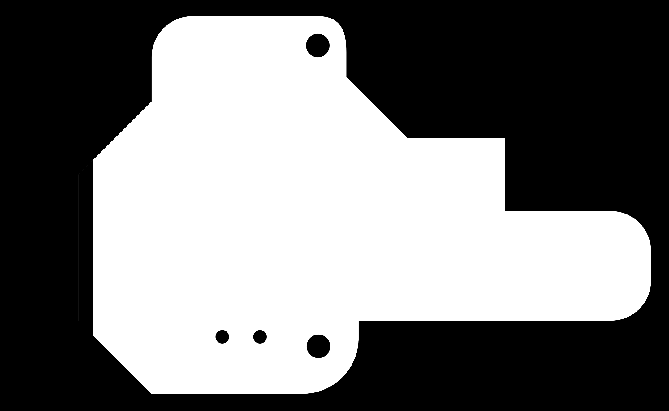
Figure 13: Child Node Cut
Here are my circuit designs. The FTDI board and the node boards are the same, minus the FTDI header. I initially designed my board in eagle, then exported the board as a monochrome PNG with a 1000 dpi. I then edited the PNG of the board in photoshop to add custom pads, vias and trace thicknesses. I added vias to my design so I could add the phototransistor and a ground line to the back of the board. Everything was placed extremely intentionally relative to the track pad. There are vinyl cut copper lines that are soldered to the large button pads on the circuit. At one point, I designed traces for the back of the board in photoshop to mill with a two sided PBC, but I ultimately decided that soldering directly to the vias and adding a copper vinyl cut trace would be cleaner and more efficient for this project.
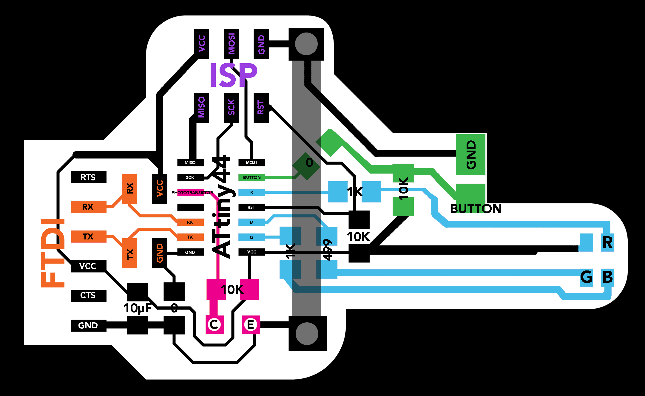
Figure 14: FTDI Board Diagram
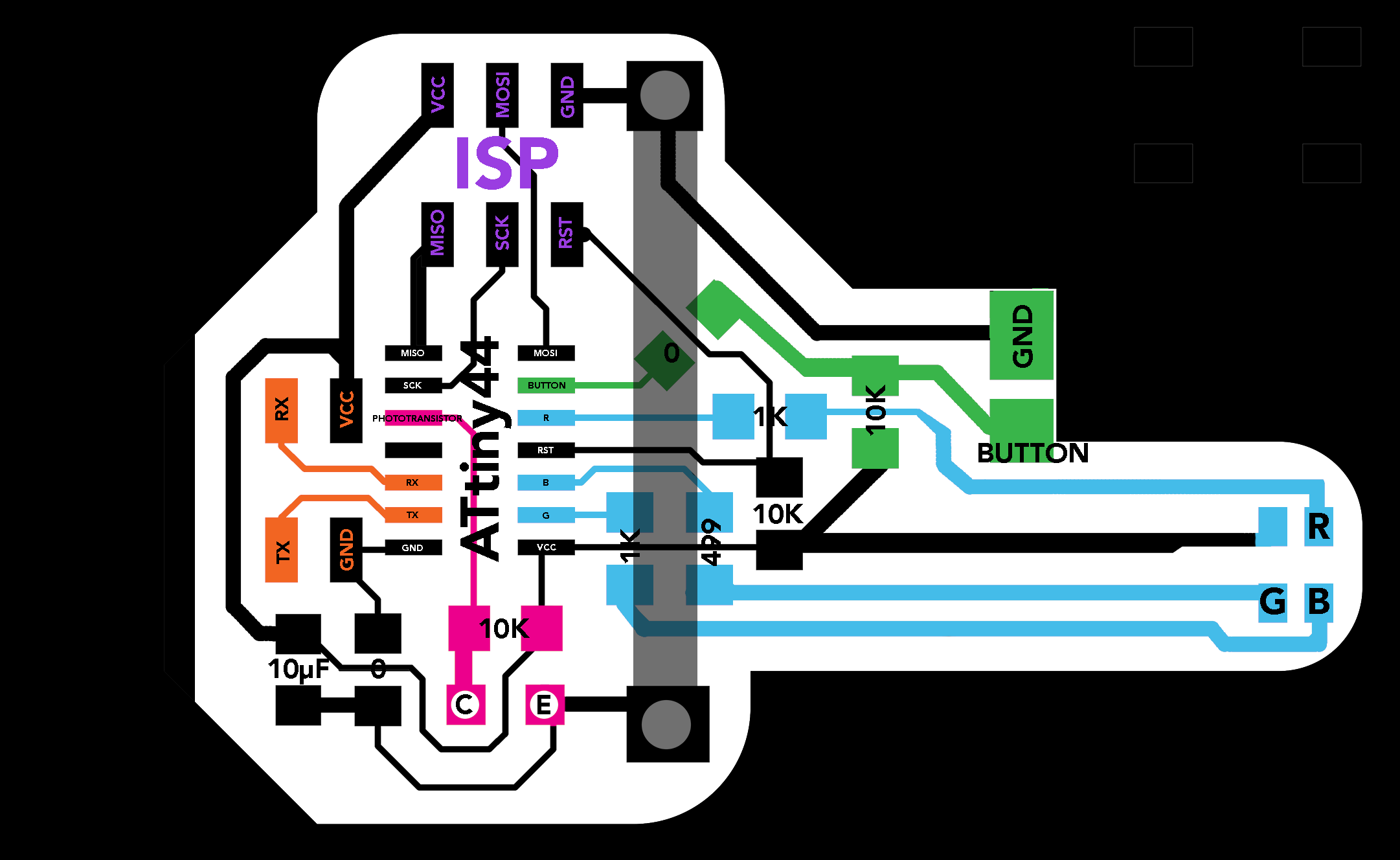
Figure 15: Child Board Diagram
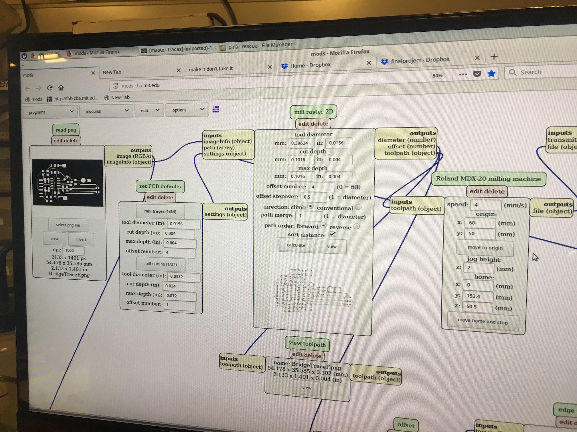
Figure 16: Mods Interface
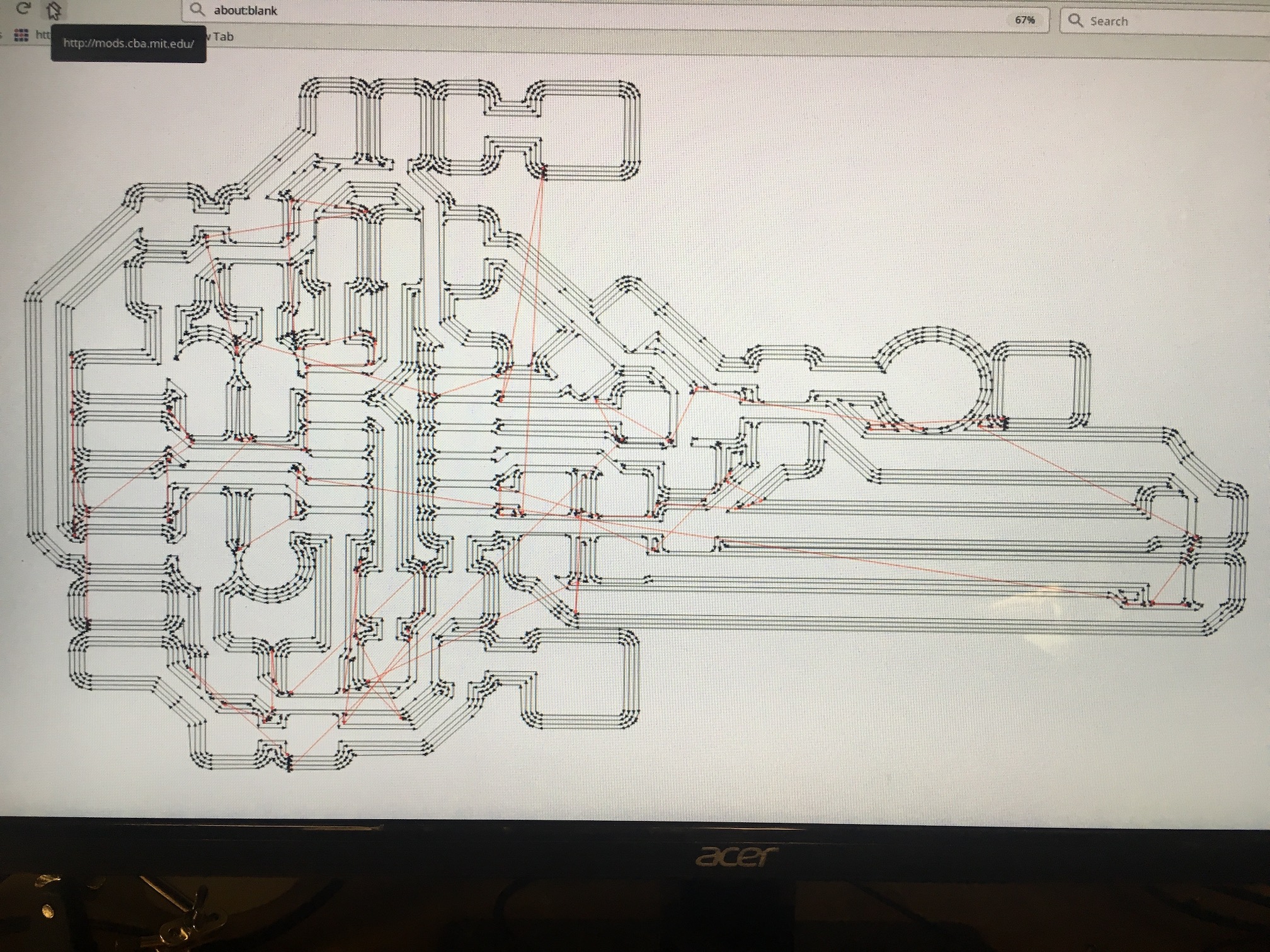
Figure 17: Toolpath Vectors for Milling Traces (note: earlier board design)
I loaded the boards into mods and used the standard settings for tracing and cutting the boards. My traces were milled with a 1/64" endmill and took about 12 minutes per board. My outlines were milled with a 1/32" endmill and look approximately 3 minutes to mill. I worked meticulously in photoshop and mods to make sure that all of my boards would be perfect for soldering when milled since I had to fabricate many of them. This meant making sure none of my traces were too thin or too close to any of the other traces such that they wouldn't be partitioned by the endmill. I'm pleased to say that I didn't have to do any electrical debugging for these boards. Lastly, while milling my board outline, I made sure to switch the toolpath direction to reverse, so the vias would be cut first. This is important because you don't want the board to disconnect from the bed of the mill by milling the outside of the board first.
Figure 18: Board Assembly
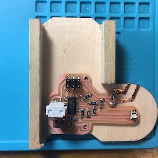
Figure 19: Assembled Board
Track Vinyl Cut Copper Design
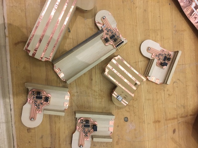
Figure 20: Copper VCC, TX, RX, and GND
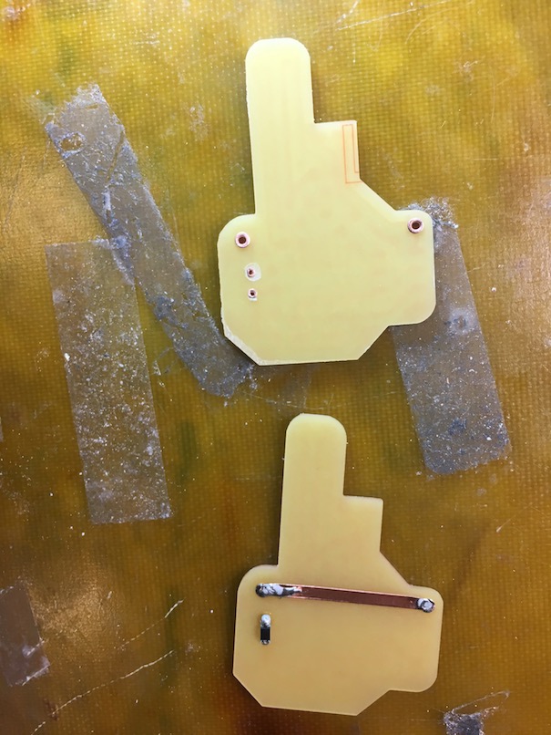
Figure 21: Soldering Copper Trace to Back of Board
I designed my copper traces to be seamlessly integrated with my track in Illustrator. I used the schematic from my circuit and the layout of the track to create precisely measured copper traces to be vinyl cut. I included a vinyl cut copper trace for the back of the board as well to avoid having to mill double sided boards. This saved time and was a safer circuit to be honest, because I didn't have any large areas of unassigned copper that could short my board.
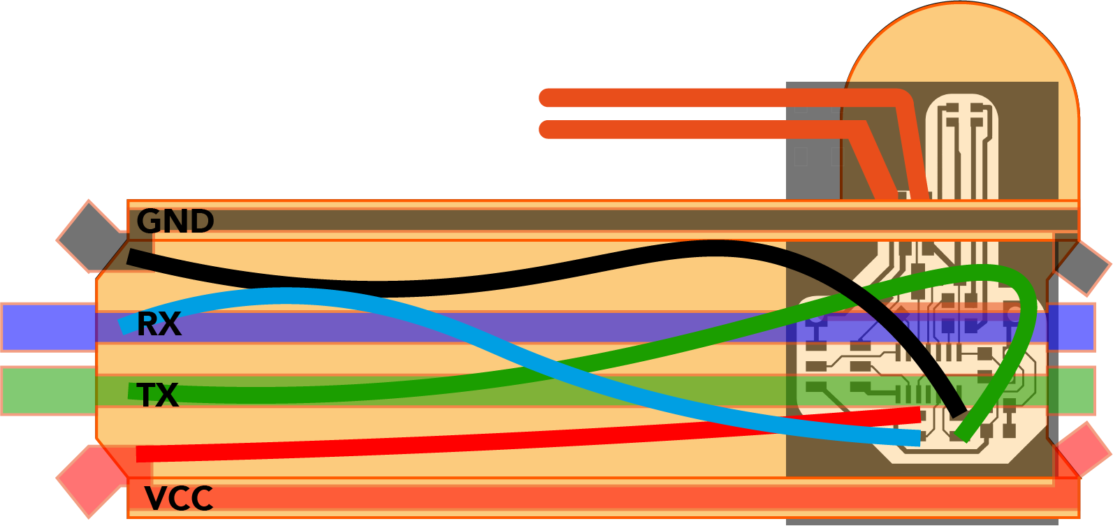
Figure 22: Final Copper Trace Integration Design
Programming
Arduino | Software Serial
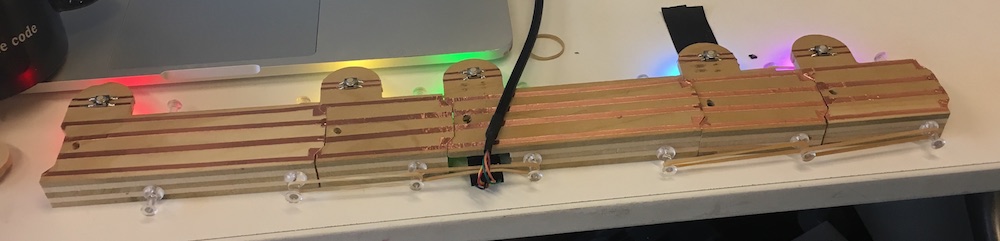
Figure 23: Yay!!!!
TRAX Arduino Software
Sam was soooooooo helpful for programming this board. Originally I thought I'd use I2C for my communication protocol, but I realized that the longer the lines could create noise on the SDA line. Instead, I opted for asyncronous communication. I added comments to my code in the text file above, however, as a brief overview, here's what it does. There's a counter that's keeping track of the current LED/note value. When the phototransistor passes a certain threshold, that triggers the TX line to transmit the state of the LED/note back to my computer serially. I used Software Serial to allow my boards to communicate back to my computer. There initially was an issue where when I connected more than one board to the TX line, the serial messaging would stop working. In discussion with Sam, we realized that I needed to pull the TX line high before switching the TX line from input to output when each track had a message to send.
Figure 24: Serial Messaging Issue in Arduino (before fix)
Max
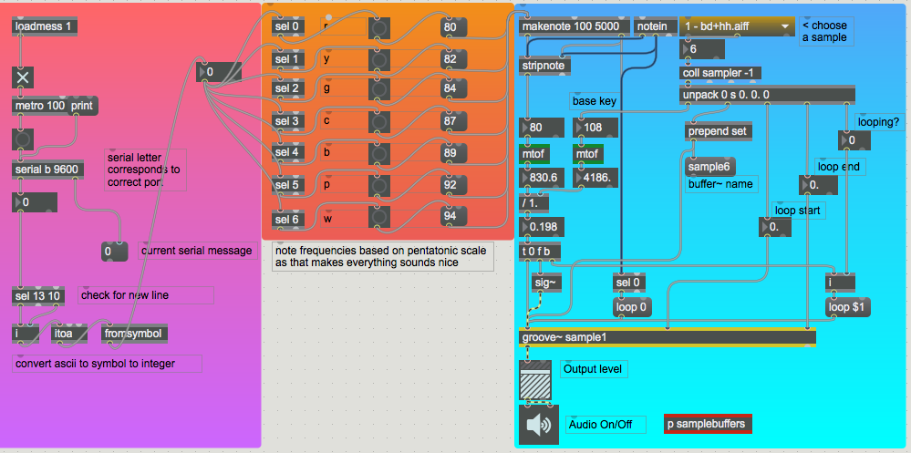
Figure 25: Max Interface
TRAX Max Software
Max has a serial communcation node, so I used that to stream my serial data, from there, I check for a carriage return signal, and when that's received, I trigger the MIDI notes to play in max. In terms of sound design, I chose to use frequencies that created a pentatonic scale, so everything would sound pleasant while demoing my project to the class and during the open house. It got pretty loud during the open house, so I modified the base key for my instrumentation, which raised the frequency and allowed visitors to hear my project more clearly.
Figure 26: Demoing TRAX to my labmate!
integration
I really wanted these train tracks to be magnetically connected. However, the tracks needed to be pretty precisely aligned to connect VCC, GND, Tx, and Rx properly, so ultimately I resorted to hacking my project. I emailed out to Object Based Media with a SOS email and Dan Novy pitched the amazing idea to use thumb tacks and rubber bands to hold my track pieces together. You can check out the video below to see what I mean. Although my train light worked on the track, while demoing my project, I discovered it was super fun to scrub the tracks with a phone light! This was useful because my tracks were still very delicately connected so many people could interact with my project without risking disconnecting the track.
Figure 27: Ugh, magnetism.
result
Figure 28: Final Implementation!
what did I learn - aside from how to make (almost) anything?
Dudes! I budgeted what I thought was a generous amount of time for debugging. I thought maybe half the time spent on my project would be spent dealing with human errors on my part. Turns out, the last 1% really does take 120% of your time. Integration is hard, and I judge my project as a success by the mere statement that my system is currently networked and communicating with my computer in an polished package. There are so many points of failure in a project like this and I'm glad all my boards and connections are working. Additionally, in the future, I'd like to spend more time documenting my work. I took pictures all along the way, but in the stress of it all, I didn't write down as much as I would've liked realtime. Lastly, when it doubt, read the datasheet. VERY IMPORTANT. I was too confident about some of the orientations of SMD components (*cough*, IR LEDs, *cough*) and wasted a ton of time while trying to debug. -_-
what's next?
Next up, add more boards. Right now I only have "quarter note" and "eighth note" length boards, but it'd be nice to add longer "half note" boards. Additionally, I would like to add curved pieces of track to create musical loops. Get the magnetic connections working. Add an accelerometer to the train so there can be pitch shifting depending on the acceleration of the train. Add a motor to the train. Improve the sound design and maybe add speakers to the train and design a sound board to create on-board audio. Make it wireless (no FTDI header)?! Make a promo video and some mock-marketing material and submit to IDC.
acknolwedgements
I would like to thank the following people for their help with this project. Tom Lutz (and John), thanks for always being available to walk me through laser cutter debugging and how to use the shopbot machine at the CBA shop. Thank you also for the sick beats. Thank you Dan Novy for emotional support at the end and for the brilliant idea to use thumb tacks and rubber bands to stick the tracks together given that the magnet idea wasn't panning out for this presentation. Thank you Amanda and Grace for being amazing TAs all semester. Thank you Sam Calisch for last minute debugging for the serial connection. Saved the whole project! Thank you Jonathan Becker for staying up with me all night right before the project was due to make sure I stayed on track to finish (pun intended). And lastly, thank you to the class and Neil for an awesome semester! This class enabled me to learn so much and I'm so excited to continue to learn as I move forward with my studies.