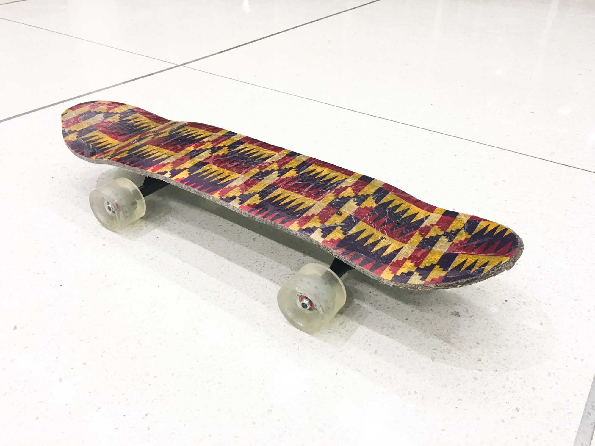
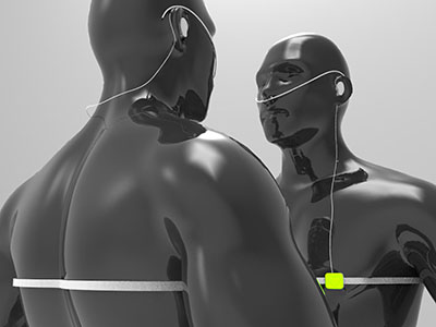
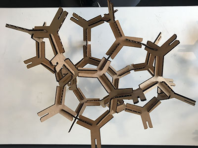
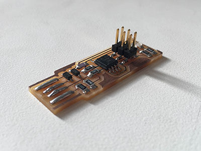
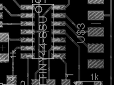
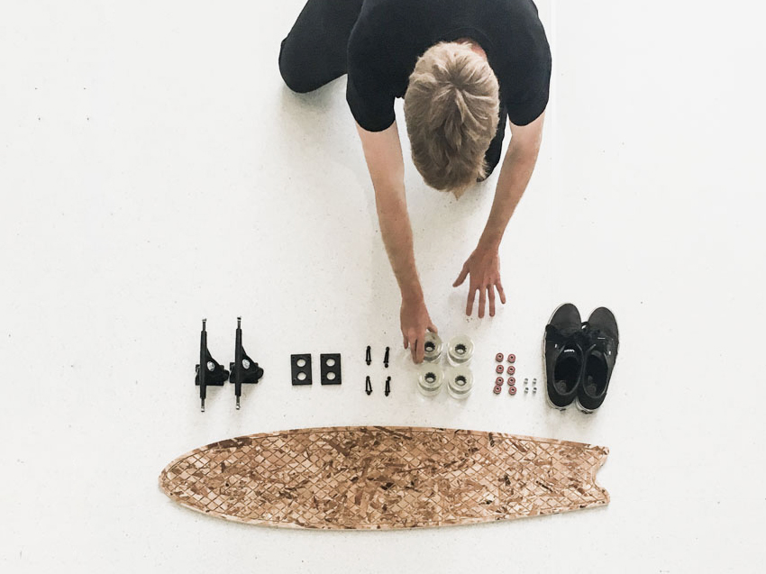
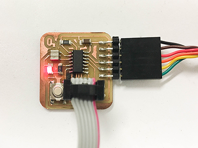
I'm a first year MAS student in Pattie Maes's Fluid Interfaces Group at the MIT Media Lab. I'm interested in augmenting human performance using design and technology. Some projects I have worked on include developing a new board for the streeboard world champion, an interface for helping you remember (almost) anything, an installation to visualize video surveillance and a 18000 spectator hockey stadium.
Document your final project progress
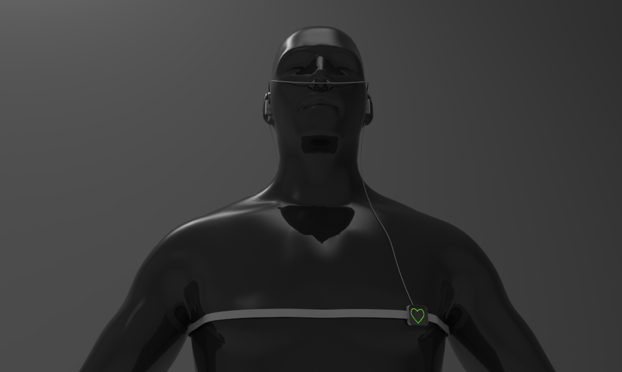
For this class, I’m interested in building a wearable device that augments our self-awareness. One idea for a final project is building a biofeedback device to guide my meditation practice.
Over the past years, multiple commercial hardware has appeared, such as the Muse headband, that teaches novices to meditate by giving users audio feedback of their own brain activity using electroencephalography (EEG) sensors.
I suspect that ampliflying other biometric information, such as heart rate, breathing, galvanic skin response and providing it to the user in real time can help novices guide their meditation practice.
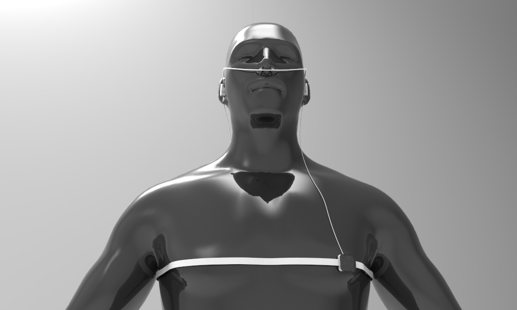
What if you could hear your heartbeat in realtime and see how different breathing patterns affect your heartbeat? What effects does seeing your own heart beat have during the meditation practice? Would playing a synthesized sound everytime we exhale help us regulate our breathing rythm?
Ideally, collecting all this information can help in augmenting our perception of our condition and see how altering parameters such as breath or muscle relaxation have effects on our mental state. Existing research shows how different breathing patters can alter your heartbeat, so can we take advantage of this fact and build an interface that augments our heartbeat via visuals or sound so we can observe how breathing alters it?
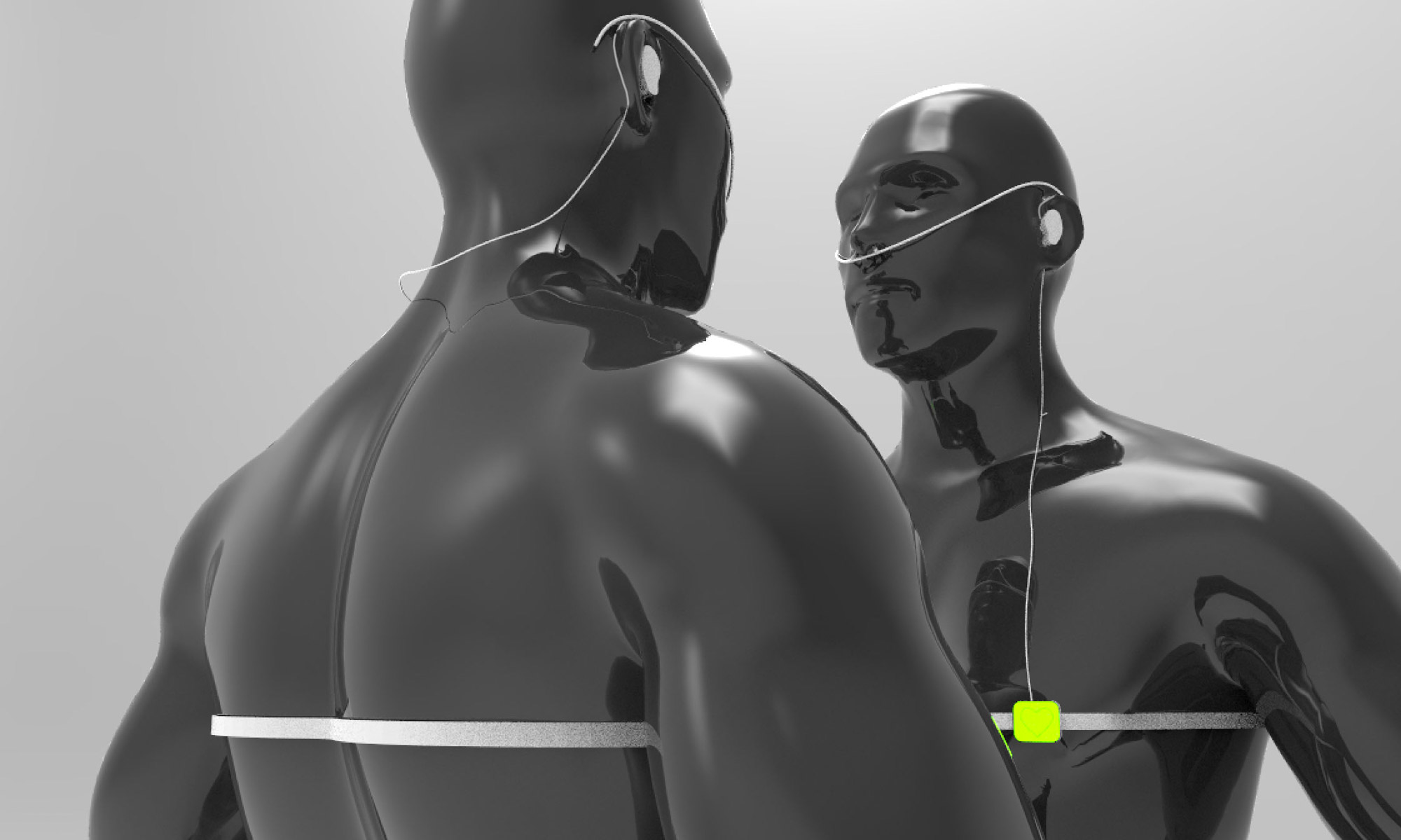
Building such a device opens up many possible combinations of interactions between more than one person. What effects would have on oneself sensing someone else's biosignals, like for example, seeing someone else's heartbeat or hearing their breathing patterns? How does the interaction between individuals change when we are aware of bodily signals that we are not usually aware of?
Inspired by how fireflies synchronize their flahsing, I'm interested in studying the cognitive effects of biosignal augmentation.

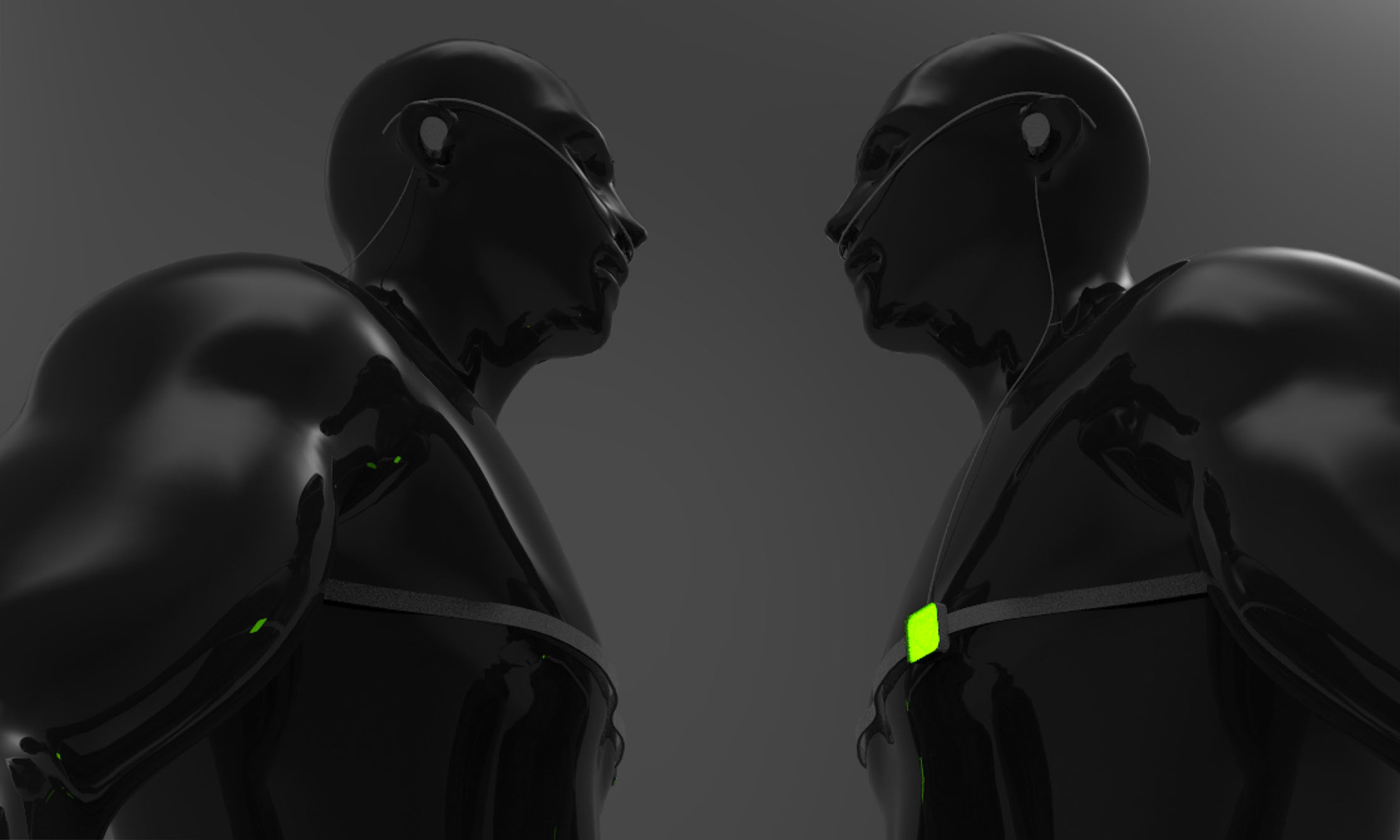
These interactions also open up the possibility of giving false feedback to subliminally alter someone else's behavior. For example, could mechanical pulsation or inflation near the alter someone else's heartbeat? Can we induce two hearts to beat as one?
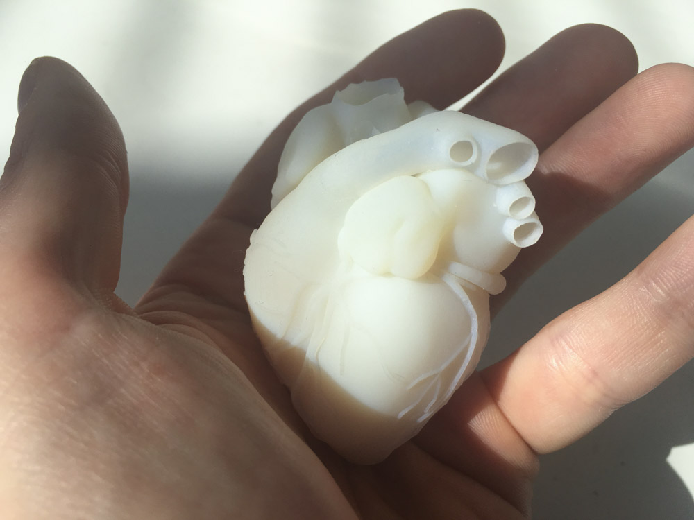
I started exploring the idea of building am externalized heart. What if I could hold on to my own heart and feel it beat in real time? How does communication change when I let someone hold my beating heart while I'm talking to them?
Using skills learned in the molding and casting week, I'm considering building a 1:1 scale model of the heart and embed the electonics inside. I could potentially build a WiFi heart that picks up my heart's beating pattern and actuates my prosthetic heart remotely.
For the heartbeat detection, I'm considering either amplyfing the audio signal of the beating heart using a stethoscope and a microphone or either using an EKG sensor.
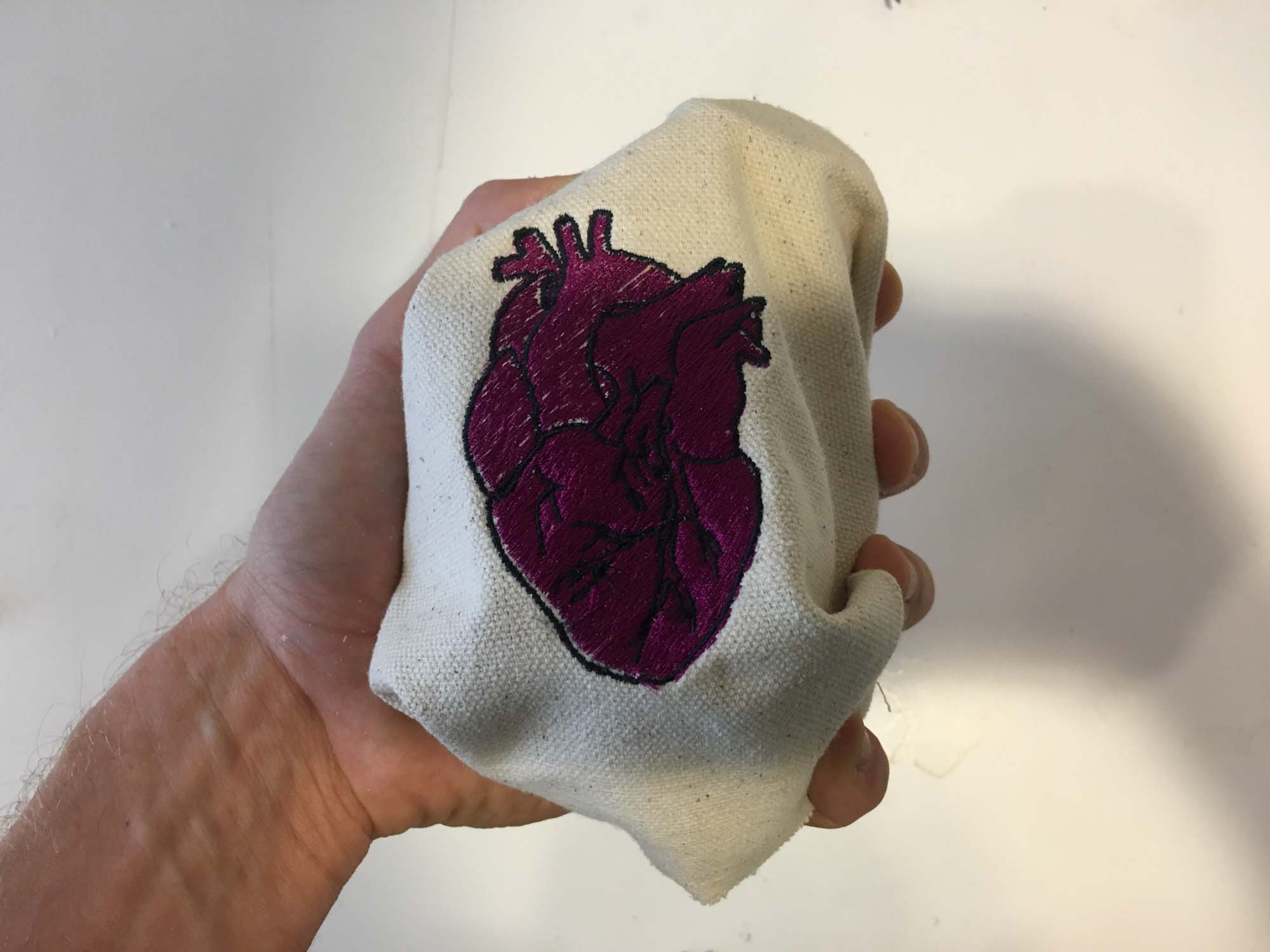
Even after having a clear idea of what I wanted to do, I decided to make a pouch to hold the heart project. I guess this was just an excuse to play around with the CNC sewing machine and learn how to use it.
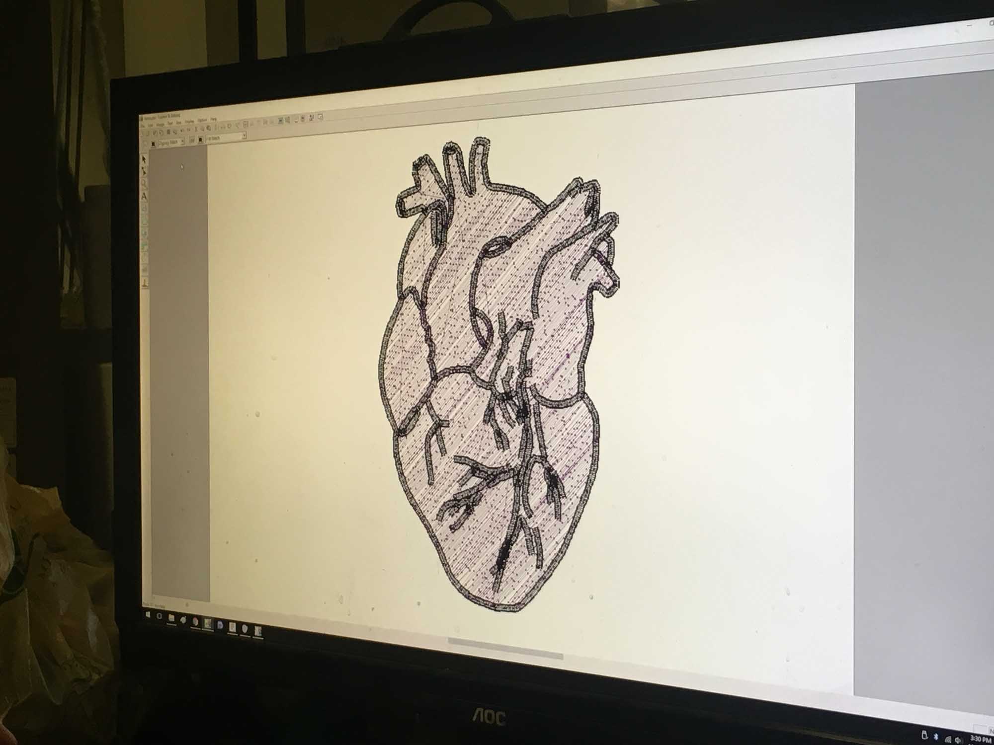
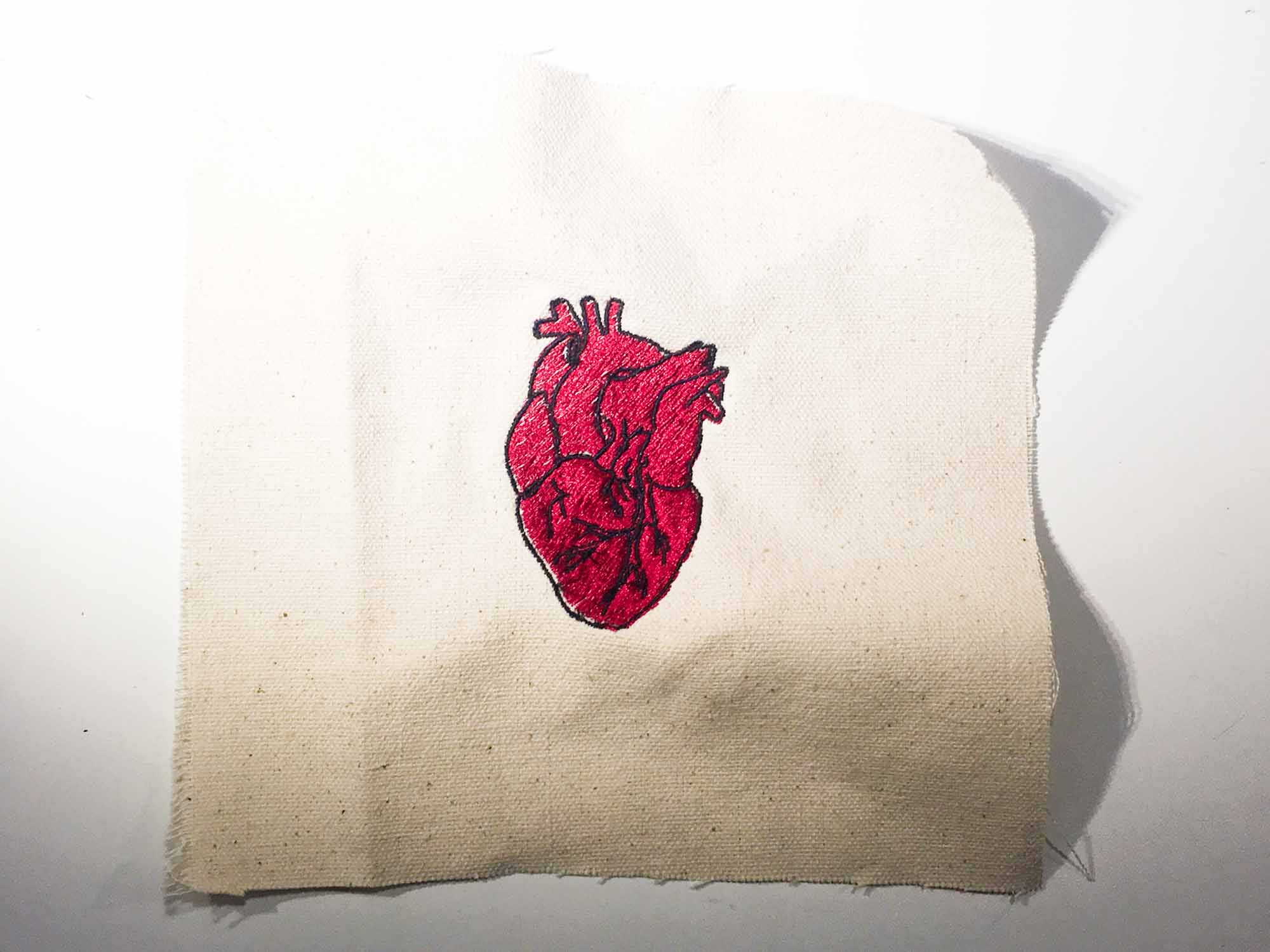
After a few iterations I settled on a concept. For the final project, I will be building an external prosthetic heart that vibrates in sync with someone's heartbeat. The motivation of this project is to increase the awareness of a specific biometric parameter and make that information available to the user as a raw signal, skipping the need to interpret data in order to extract conclusions from the interface. With this, I plan to test the idea at three different scales.
One, the personal scale, where the user can hold his or her own heart and feel their heartbeat. This could be used as a meditation device to show how people can regulate their heartbeat by changing their breathing patterns.
Two, at the couples level, where someone else can hold the user's heart. There is many biometric information that is not available when we interact with other people. How does having other information available change the interaction?
Three, at the group level. I'm interested in seeing how groups of people react to having biometric information available. A use case that I would like to try out is having a dancer wear a device that streams their current heartbeat to the audience; adding another layer of information that adds to watching a dancer perform live.
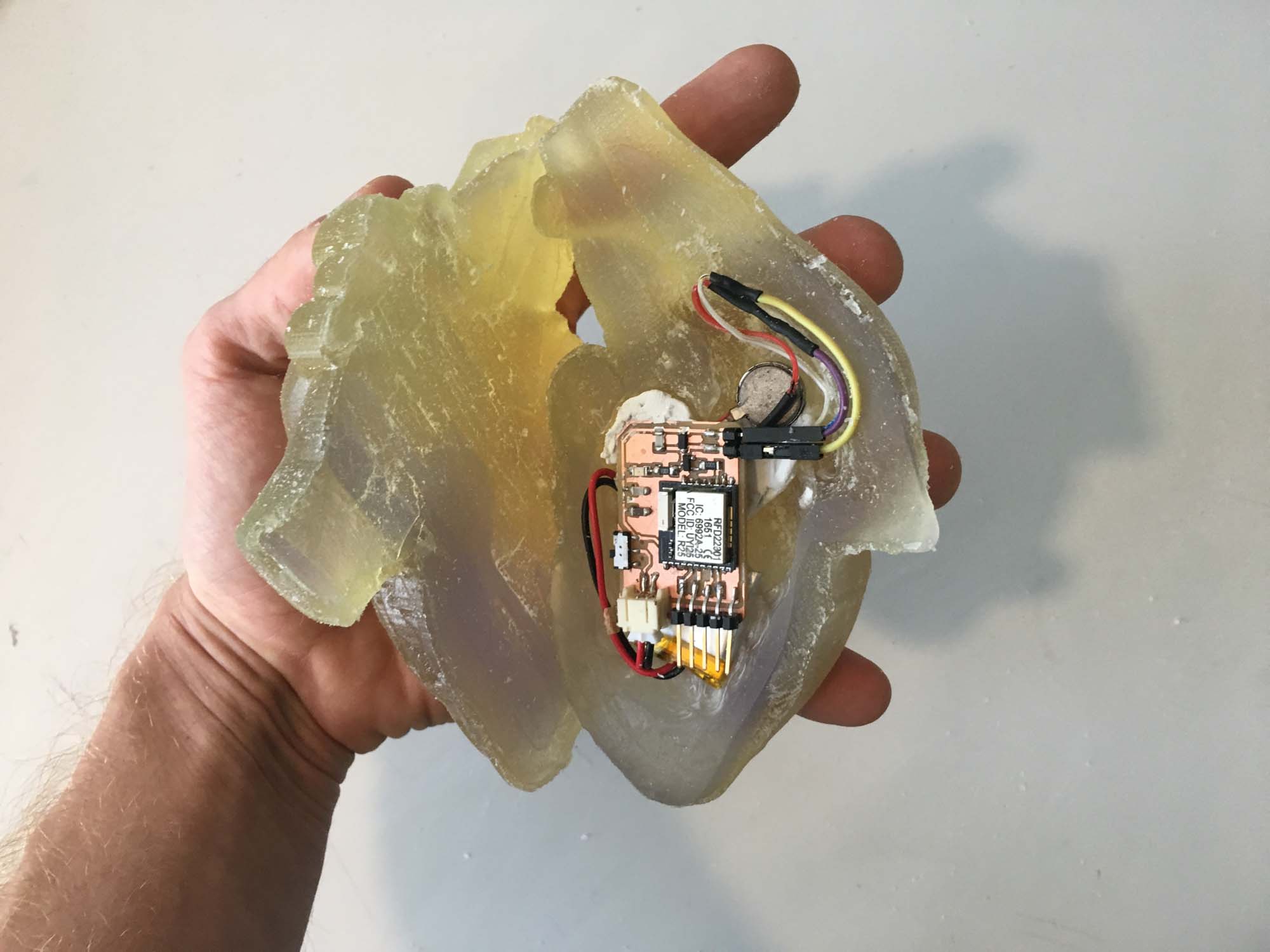
I'm planning on building the device at 1:1 scale of a heart, so I will need to fit all the electronics in that case. Also, the communication needs to be wireless between devices and battery powered to allow maximum freedom in the interaction.
Some topics I'm interested in testing incude synchoricity between users and how giving false feedback on the heartbeat can be used to condition relaxation.
The first step was building a basic board to be able to read values from a pulse sensor. As a starting point, I took the design from the board I designed in week 5 and modified it to be able to read the sensor values.
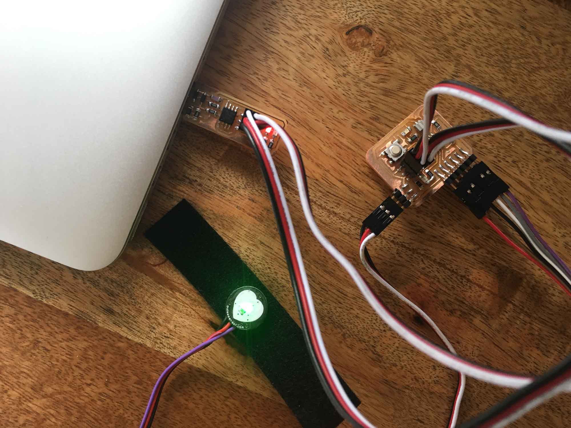

The board worked as expected and streamed values to the serial port. I used Arduino's monitor to visualize the data.
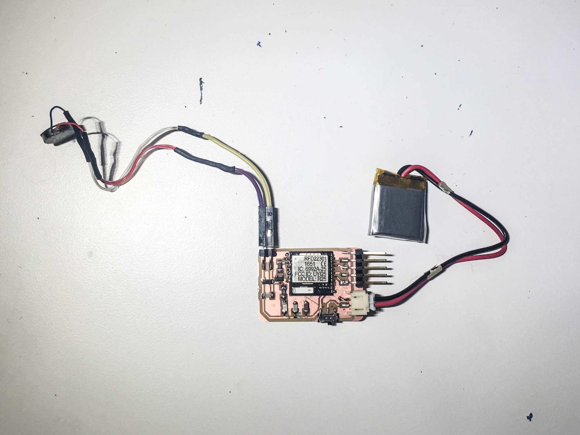
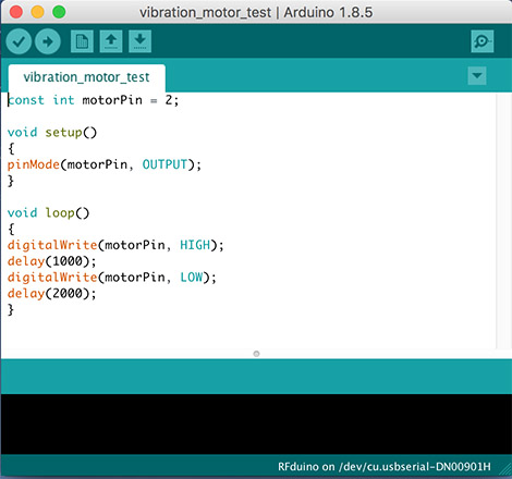
The second step was building a board to drive a vibration motor that would serve as haptic feedback for the heartbeat. To start, I just modeled the circuit for the motor and used an arduino as a microcontroller.
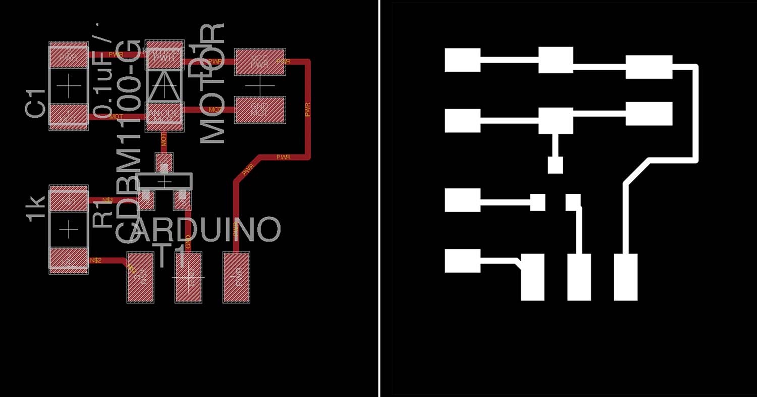
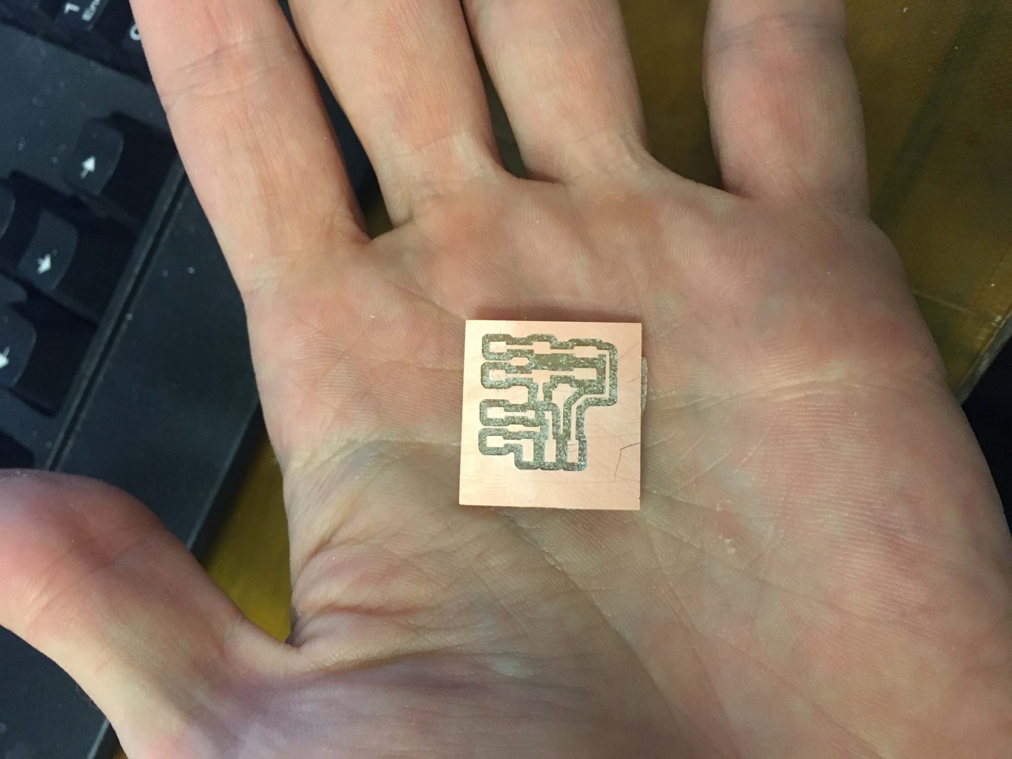
The board was vibrating nicely, so the first step towards making an autonomous board was complete.
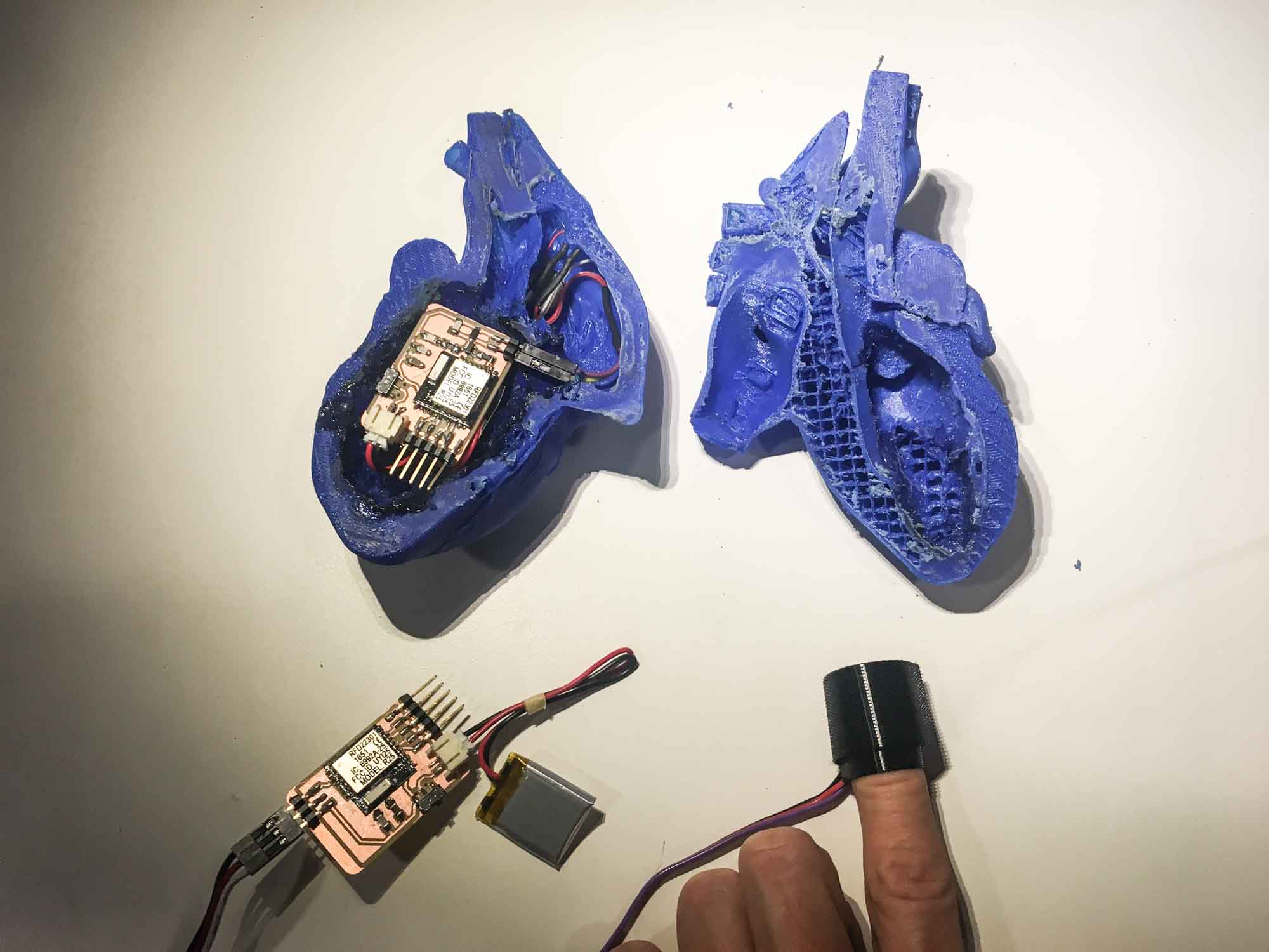
The final actuation board will read data from the heart rate sensor board and vibrate acccordingly. For the final project I worked with the RFD22301 chip, mainly to facilitate networking and to make a board that was small enough to fit in my heart model which was at 1:1 scale. Tomas helped out in the design and debugging of he hardware. Thanks man!
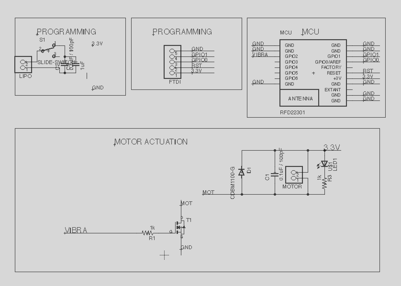
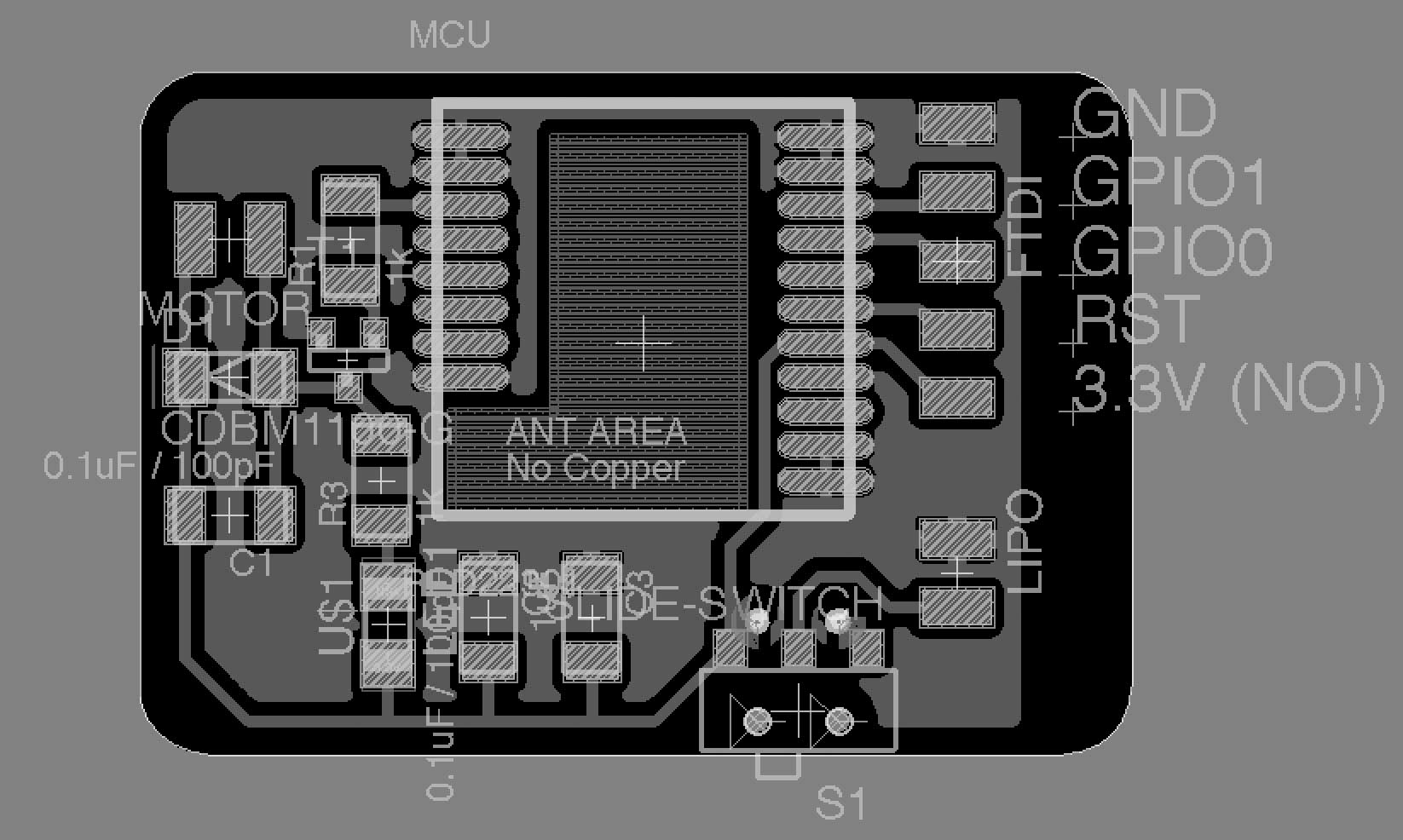
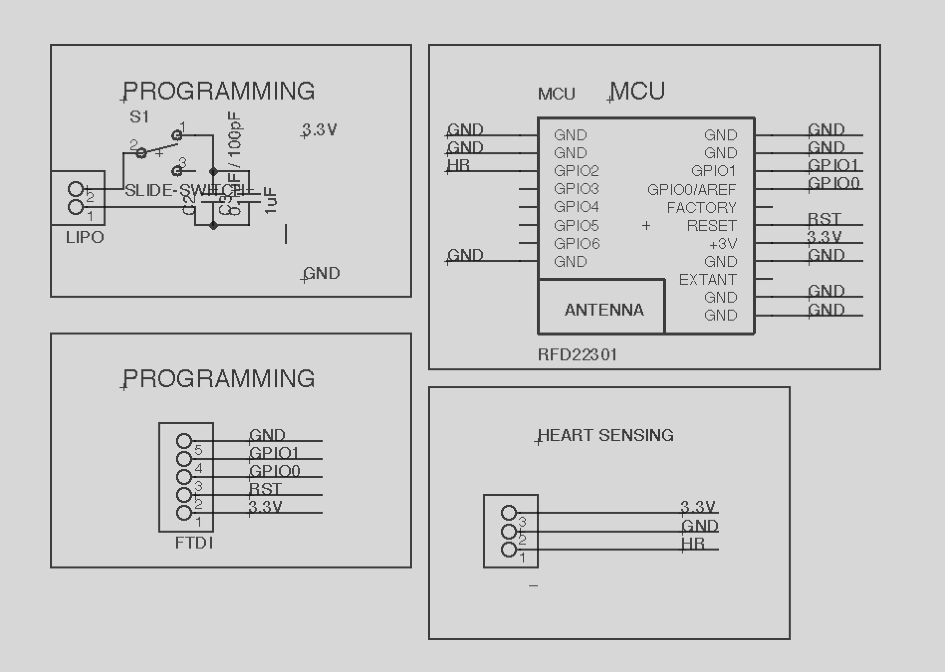
The sensor board needs to sense data from a heart rate sensor and stream it via Bluetooth to the actuation board. This board is just a variation on the actuation board that I designed earlier.
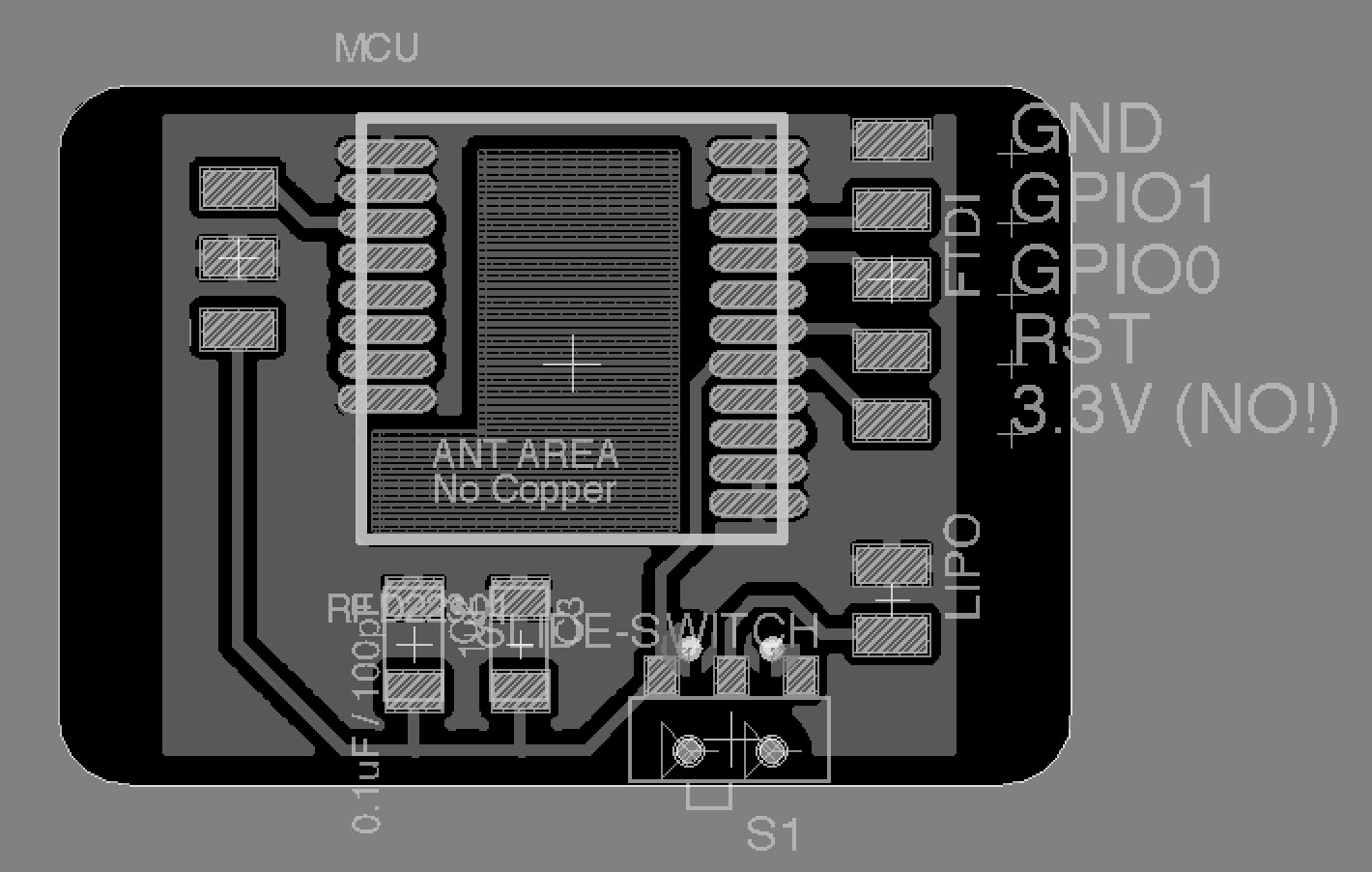
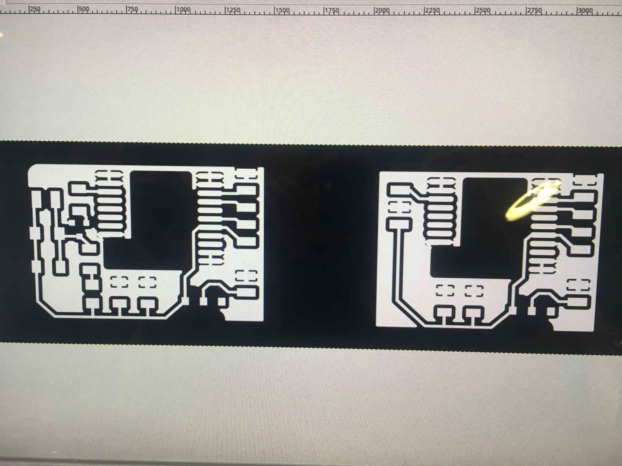
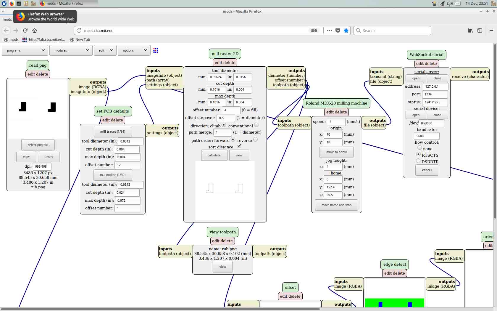
The boards were milled in 3 passes, one for the traces, a second one for the hole fittings for the switch and a third one for the contour cutout.
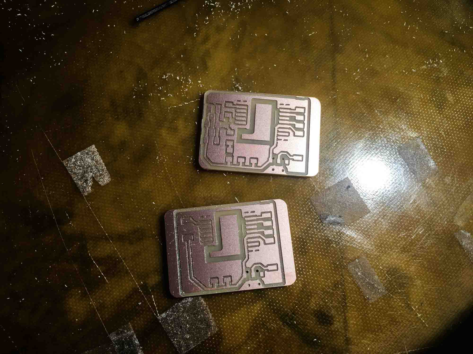
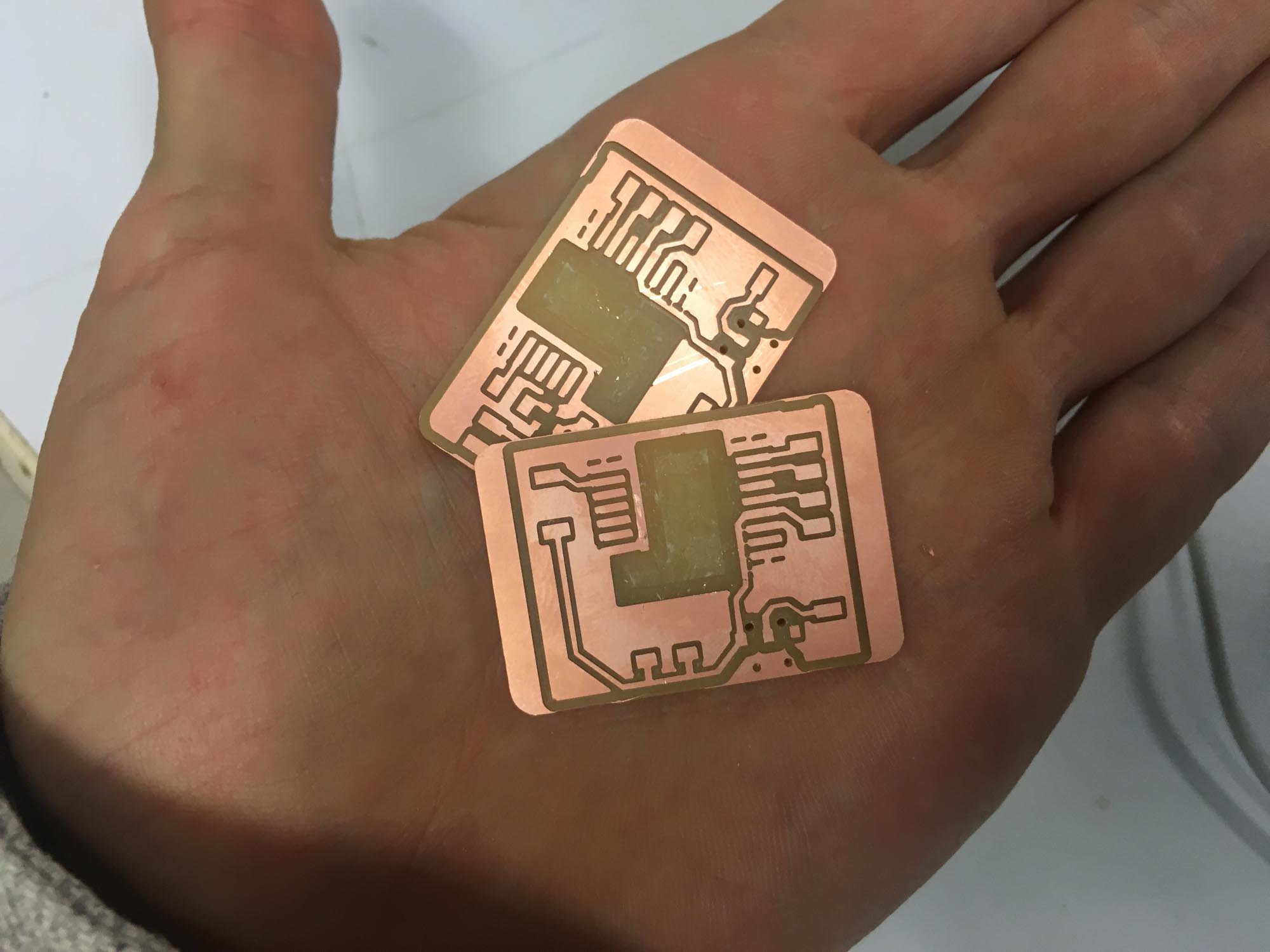
Some of the traces were not fully cut, so I had to clean up the design by hand using an Xacto knife. After, I checked all routes for continity and went on to stuff the board.
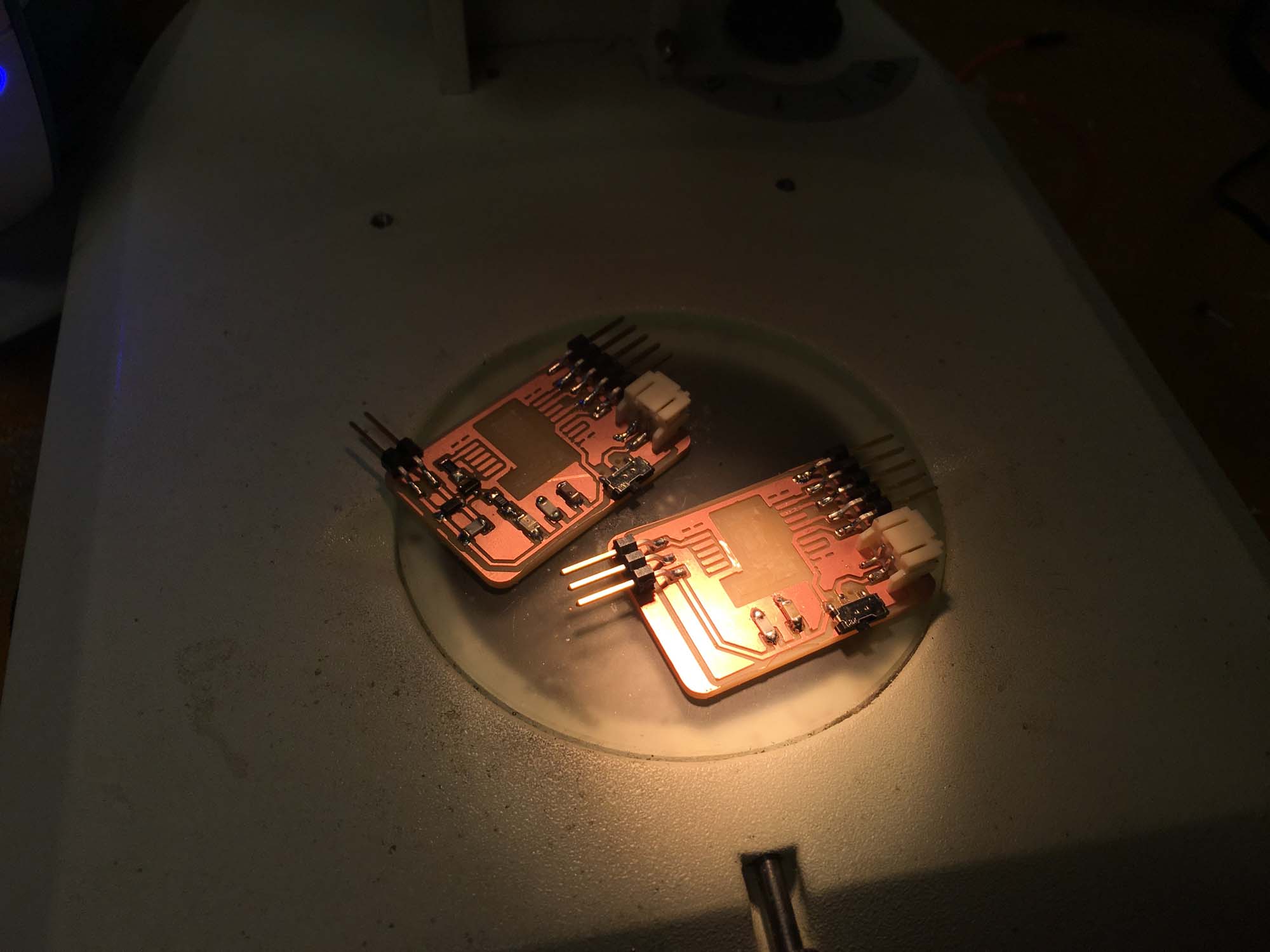
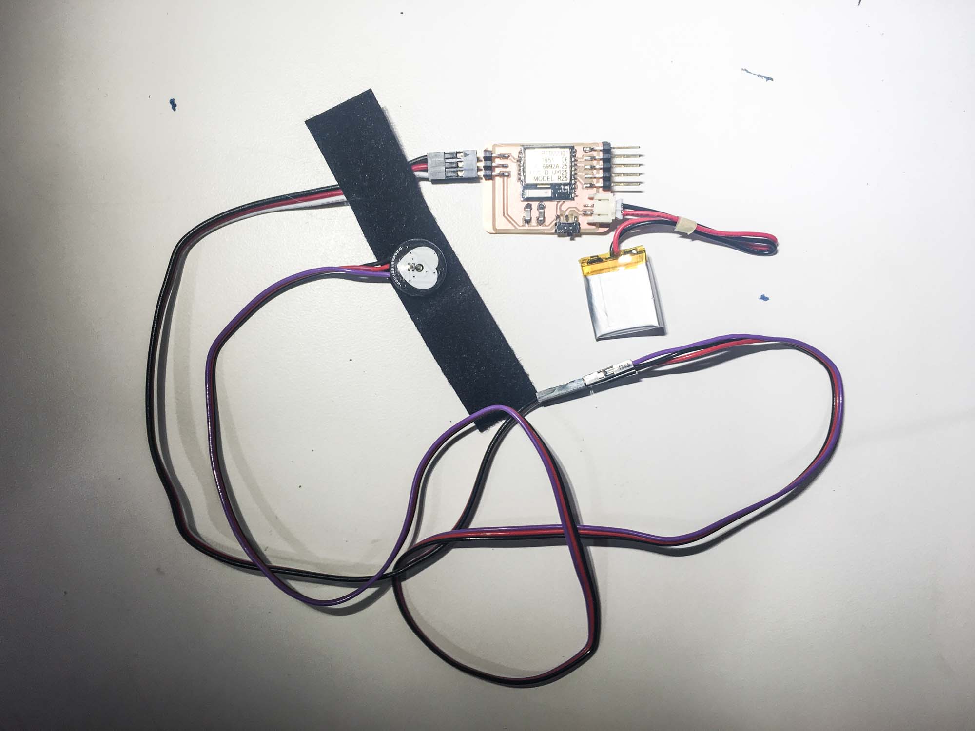
I programmed the sensor board to read values from the pulse sensor and send them over to my computer via the usb serial port.
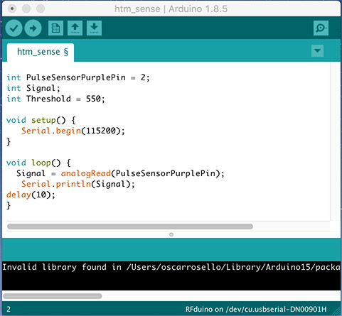
I programmed the actuation board to read values from my computer and actuate the vibration motor and an LED on the board.
The communication between the boards was done over Bluetooth using the Gazell protocol.
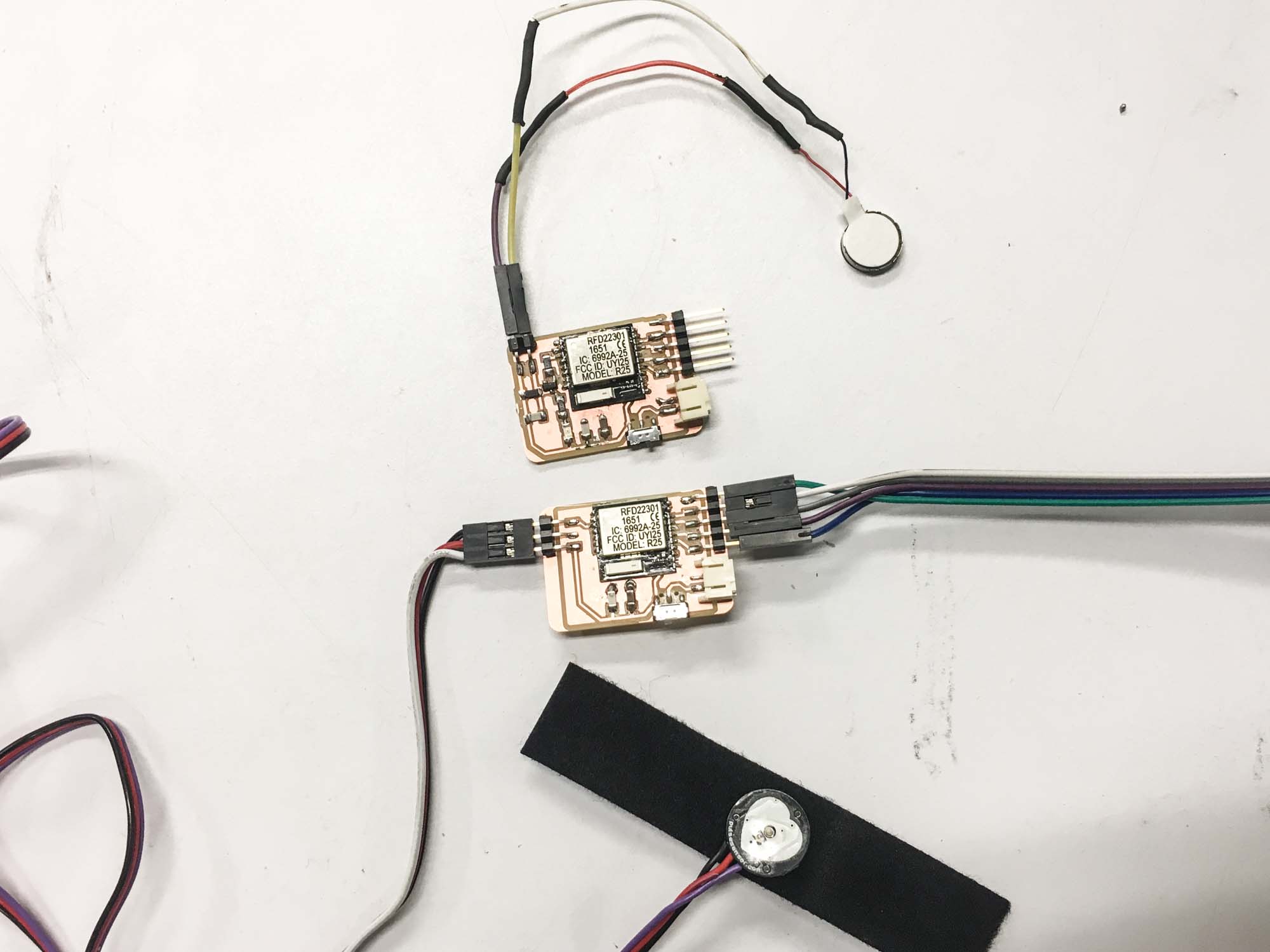
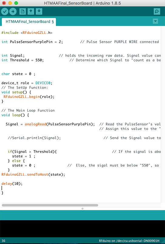
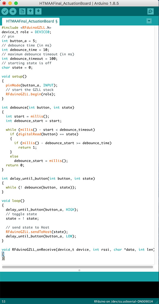
The sensor board reads the values from the pulse sensor and sends them over Bluetooth to the actuation board that vibrates in sync with the pulse. Also an LED blinks when the board vibrates.
I slit up the CAD model in two even parts and did some preliminary mesh cleanup in Rhino.
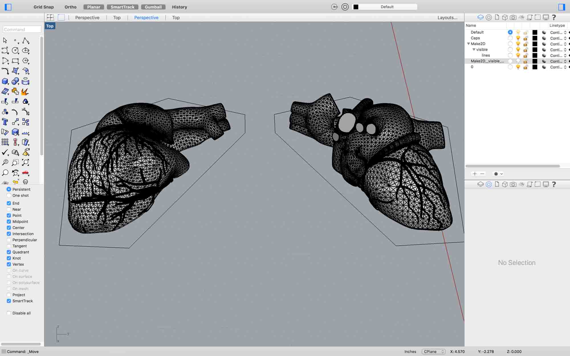
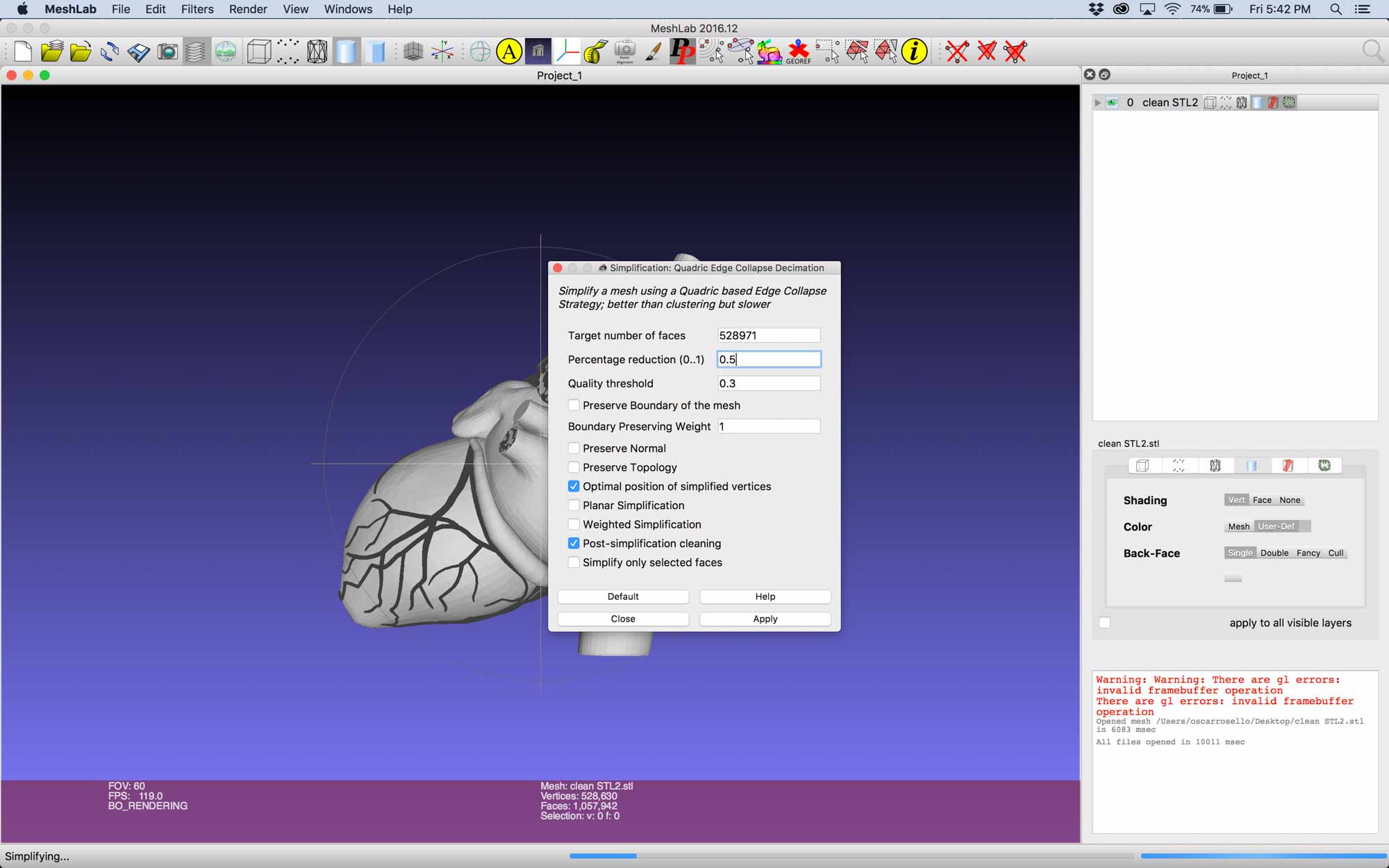
After, I did some further cleaning using Meshlab and remeshed and simplified the model to facilitate printing. I used the quadratic based edge collapse strategy to simplify the mesh.
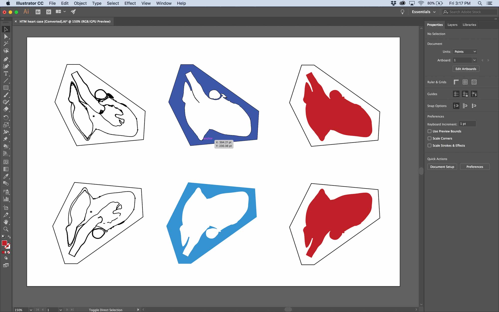
I added a few details to make sure the two parts had enough surface area to snap together.
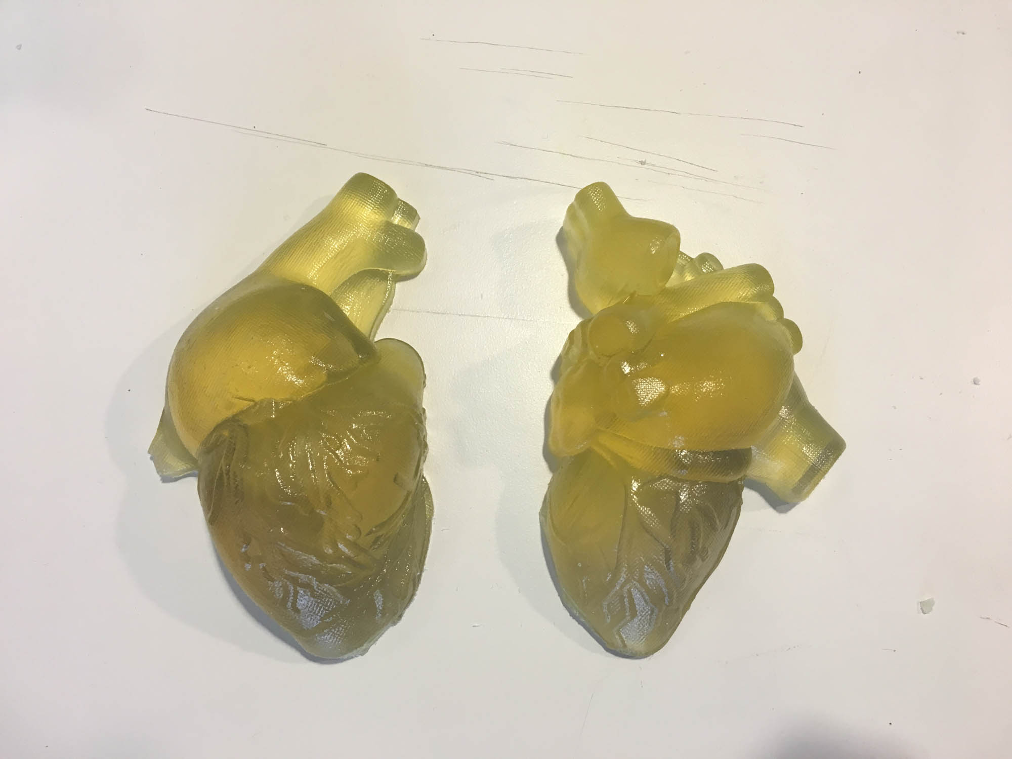
I used the Ultimaker 2+ to prototype a case for the heart and make sure the board could fit nicely in.
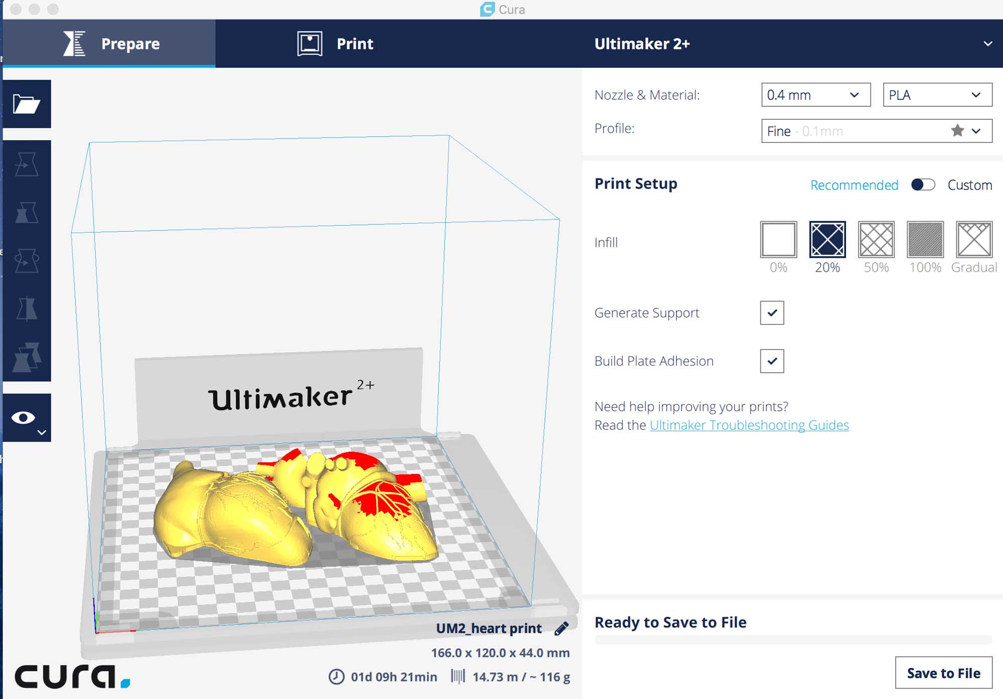
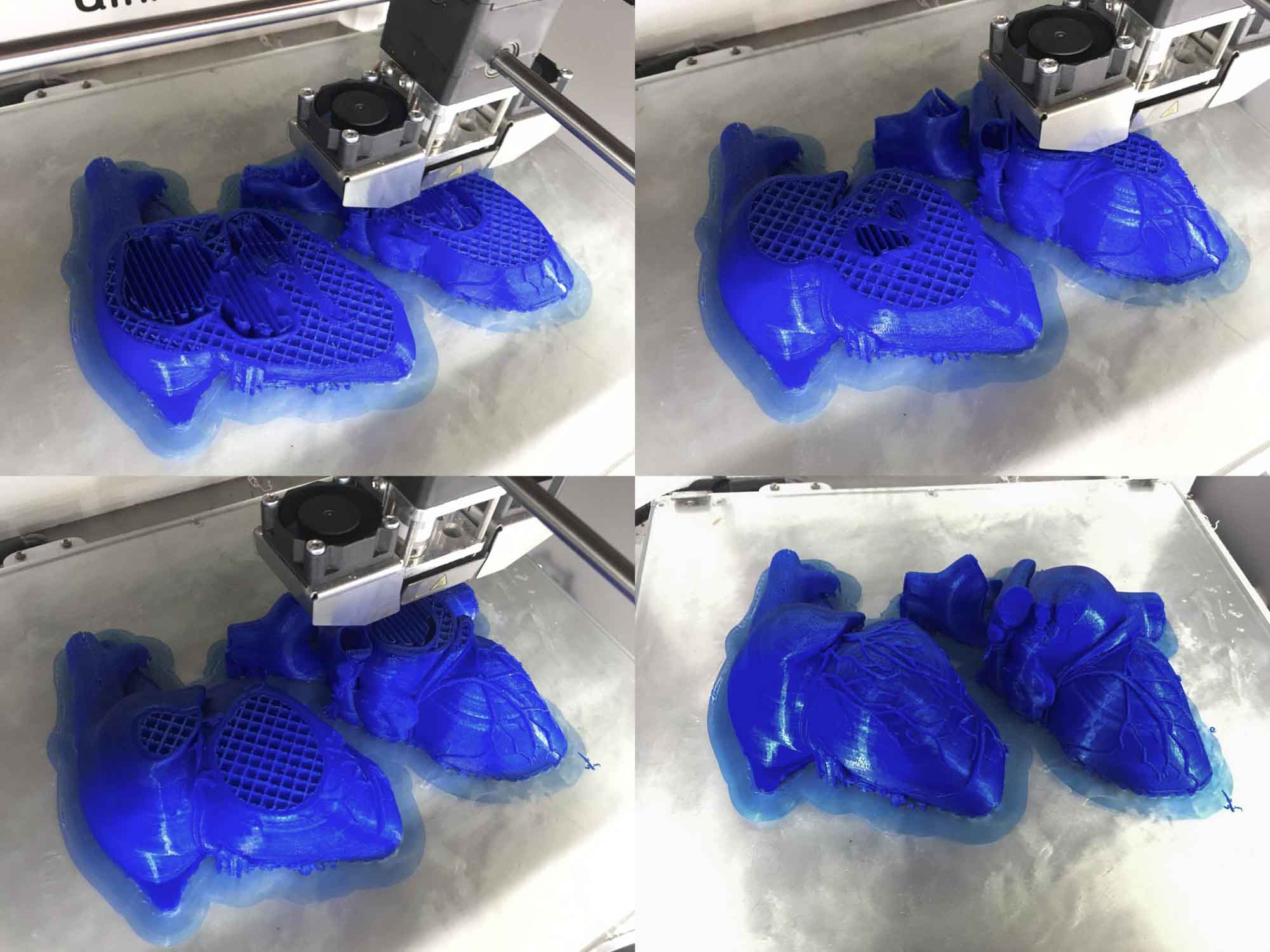
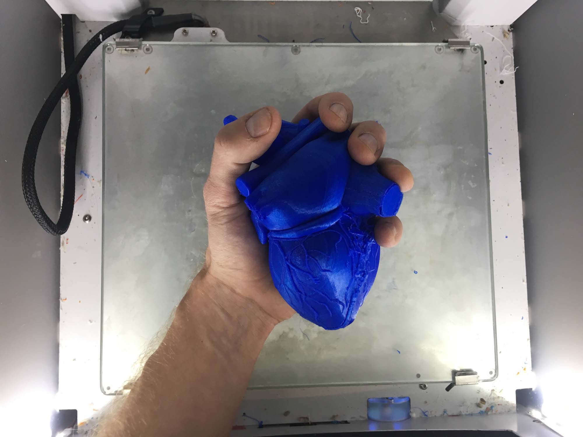
The heart was printed at 1:1 scale to be able to experience what it feels to hold a life size human heart in your hand.
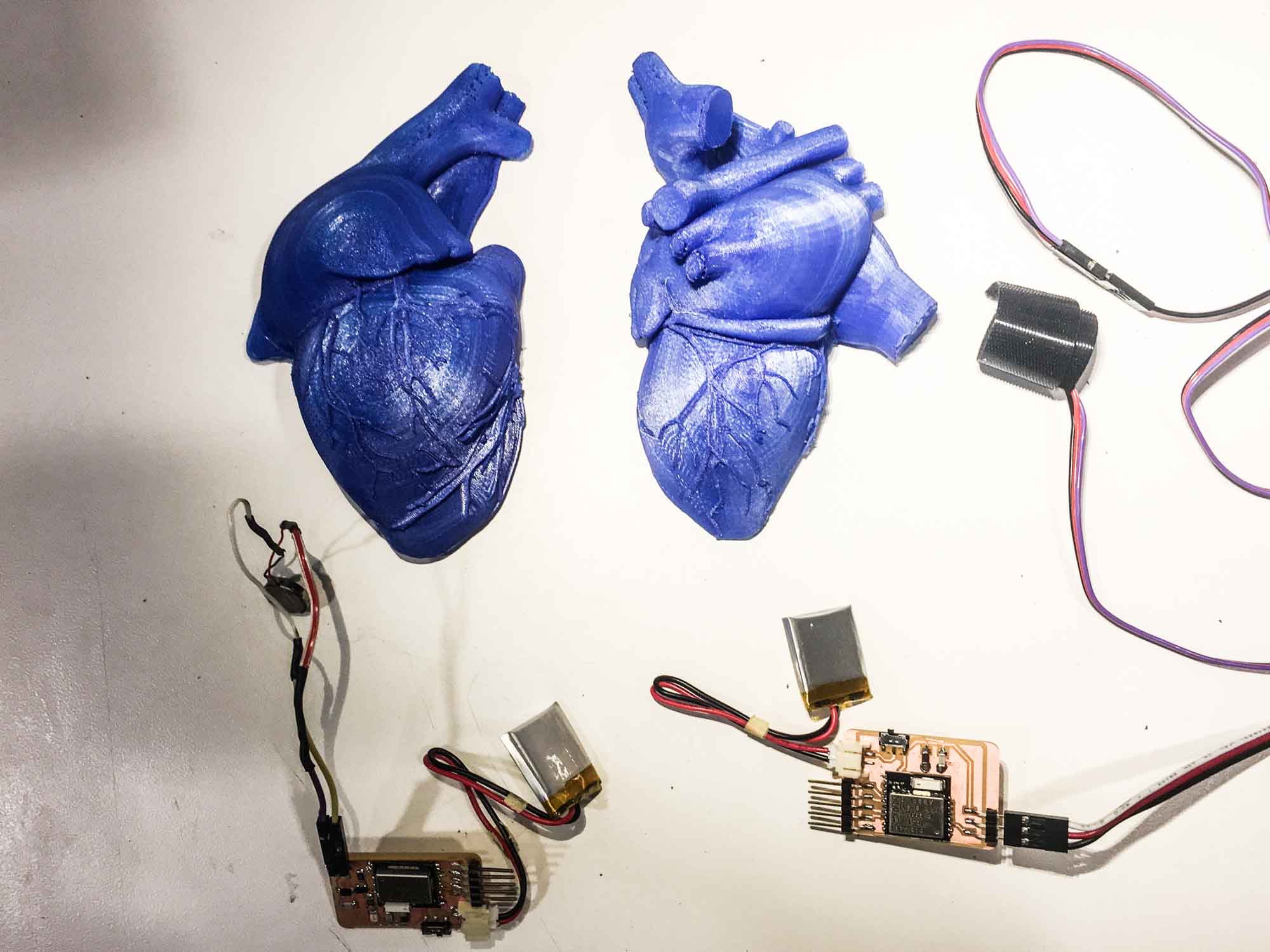
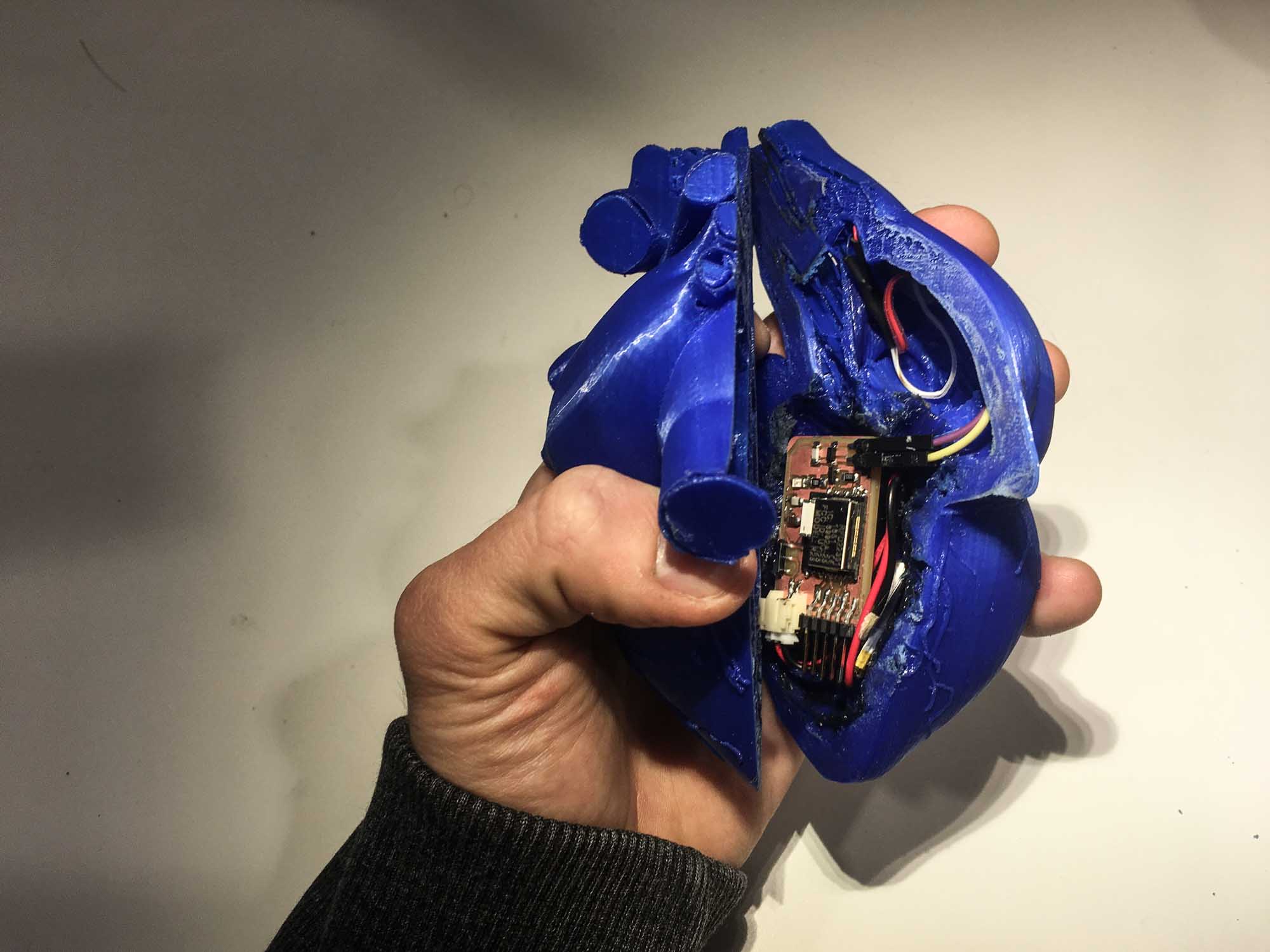
I had a few people sense the pulse with one hand and feel the vibration of the motor on the other hand to test what the experience would be like.

Plan and sketch a potential final project.

For this class, I’m interested in building a device that augments our self-awareness. One idea for a final project is building a biofeedback device to guide my meditation practice.
Over the past years, multiple commercial hardware has appeared, such as the Muse headband, that teaches novices to meditate by giving users audio feedback of their own brain activity using electroencephalography (EEG) sensors.
I suspect that using other biometric information, such as heart rate, breathing, galvanic skin response or forehead temperature variation can help novices guide their meditation practice.

What if you could hear your heartbeat in realtime and see how different breathing patterns affect your heartbeat? What effects does seeing your own heart beat have during the meditation practice? Would playing a synthesized sound everytime we exhale help us regulate our breathing rythm?
Ideally, collecting all this information can help in augmenting our perception of our condition and see how altering parameters such as breath or muscle relaxation have effects on our mental state.

Building such a device opens up many possible combinations of interactions between more than one person. What effects would have on oneself sensing someone else's biosignals, like for example, seeing someone else's heartbeat or hearing their breathing patterns?
Inspired by how fireflies synchronize their flahsing, I'm interested in studying the cognitive effects of biosignal augmentation.


These interactions also open up the possibility of giving false feedback to subliminally alter someone else's behavior. For example, could mechanical pulsation or inflation near the alter someone else's heartbeat? Can we induce two hearts to beat as one?
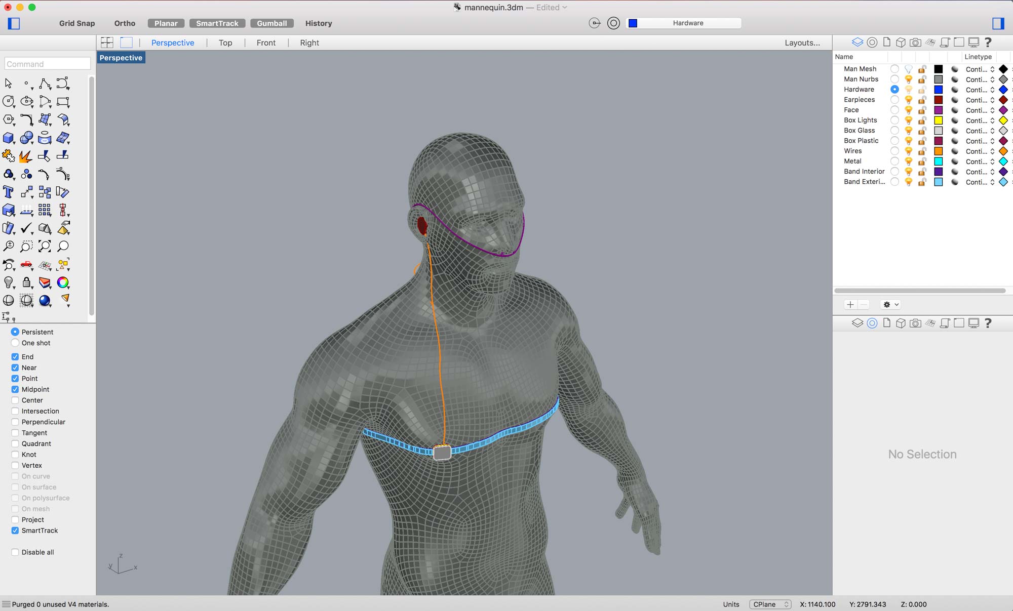
The concept was modelled in Rhinoceros 3D, a popular NURBS CAD package and textured and rendered in Keyshot.
Design, make, and document a parametric press-fit construction kit, accounting for the lasercutter kerf, which can be assembled in multiple ways.
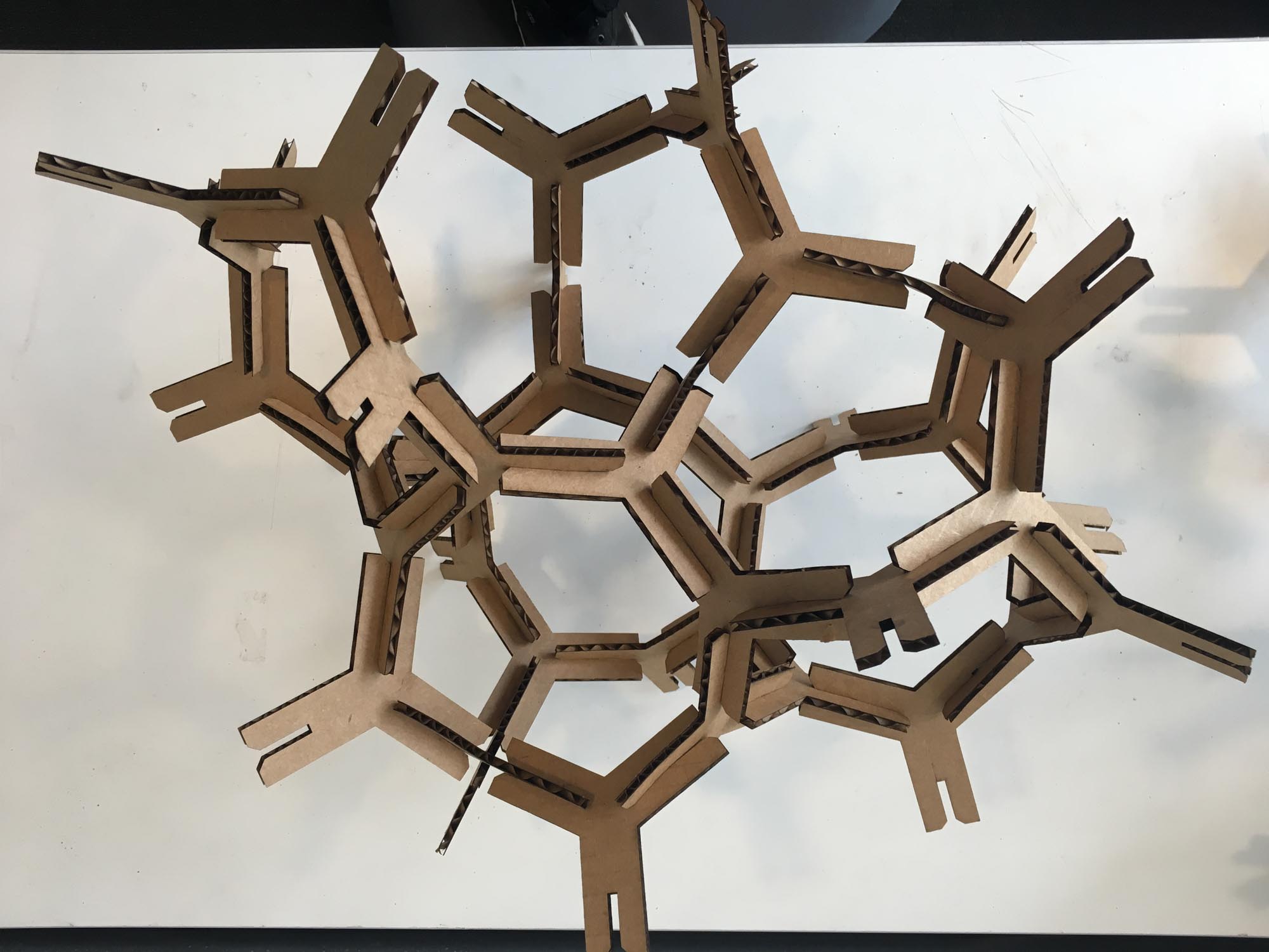
This week, we are designing and building a laser cut press fit construction kit. For my kit, I wanted to follow a dumb unit, smart system approach. That is, how can you build a complex spatial structure from very simple building units.
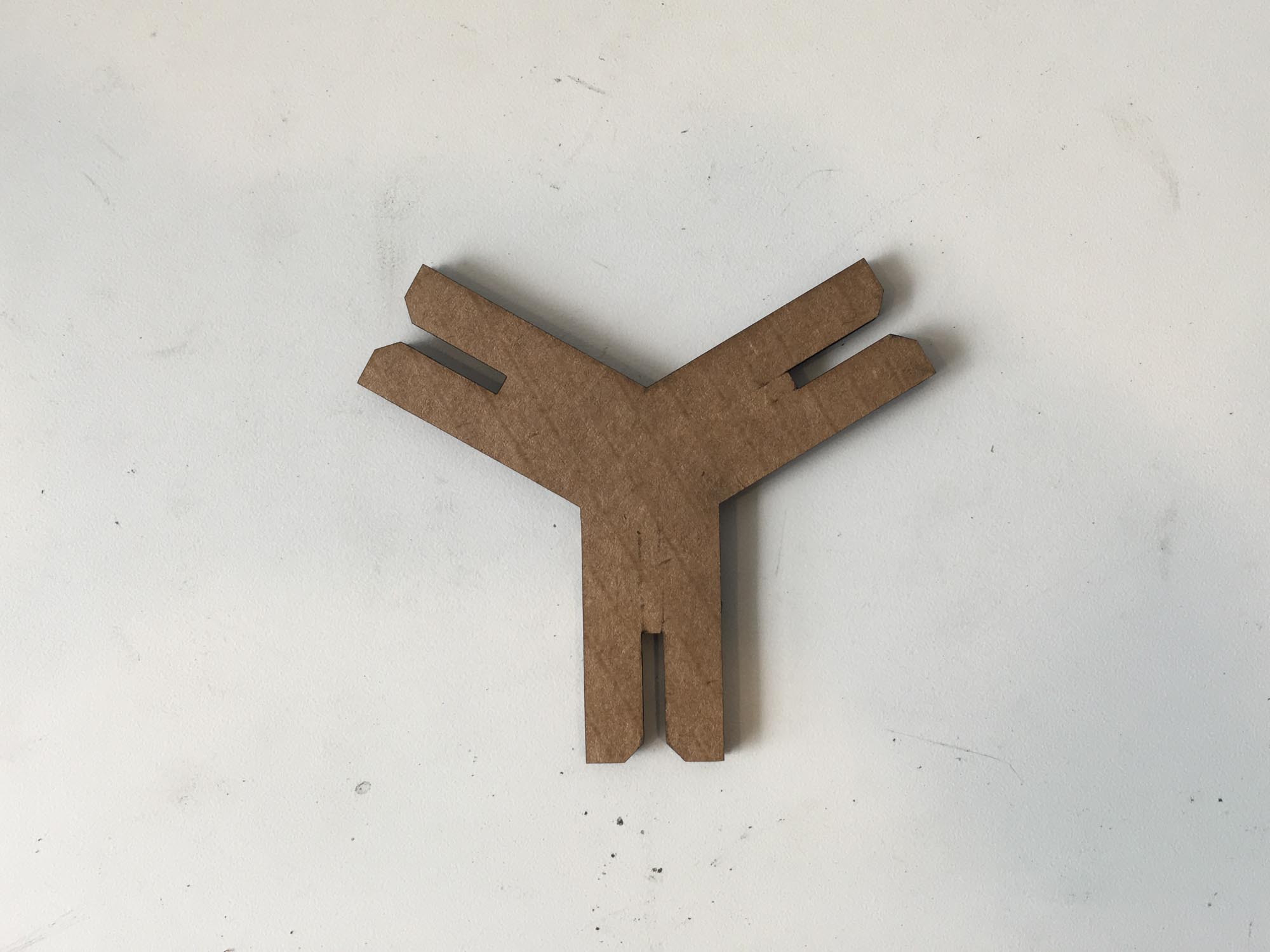
The base unit is a parametric fork, built in Grasshopper for Rhino that takes into account the kerf of the laser cutter and enables the user to modify the slot dimension to account for different material ticknesses.
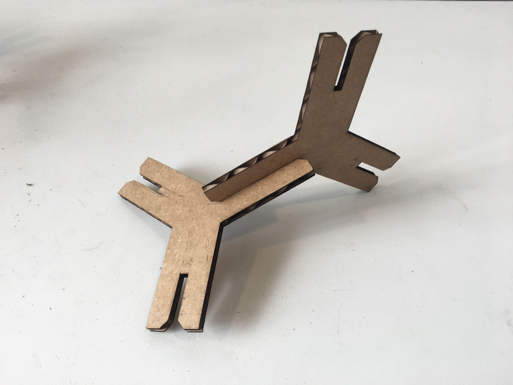
The building kit grows by adding two or more pieces together. The assembly process turned out to be much more fun than what I was anticipating and I ended up spending more time playing with the parts than cutting them on the laser cutter.
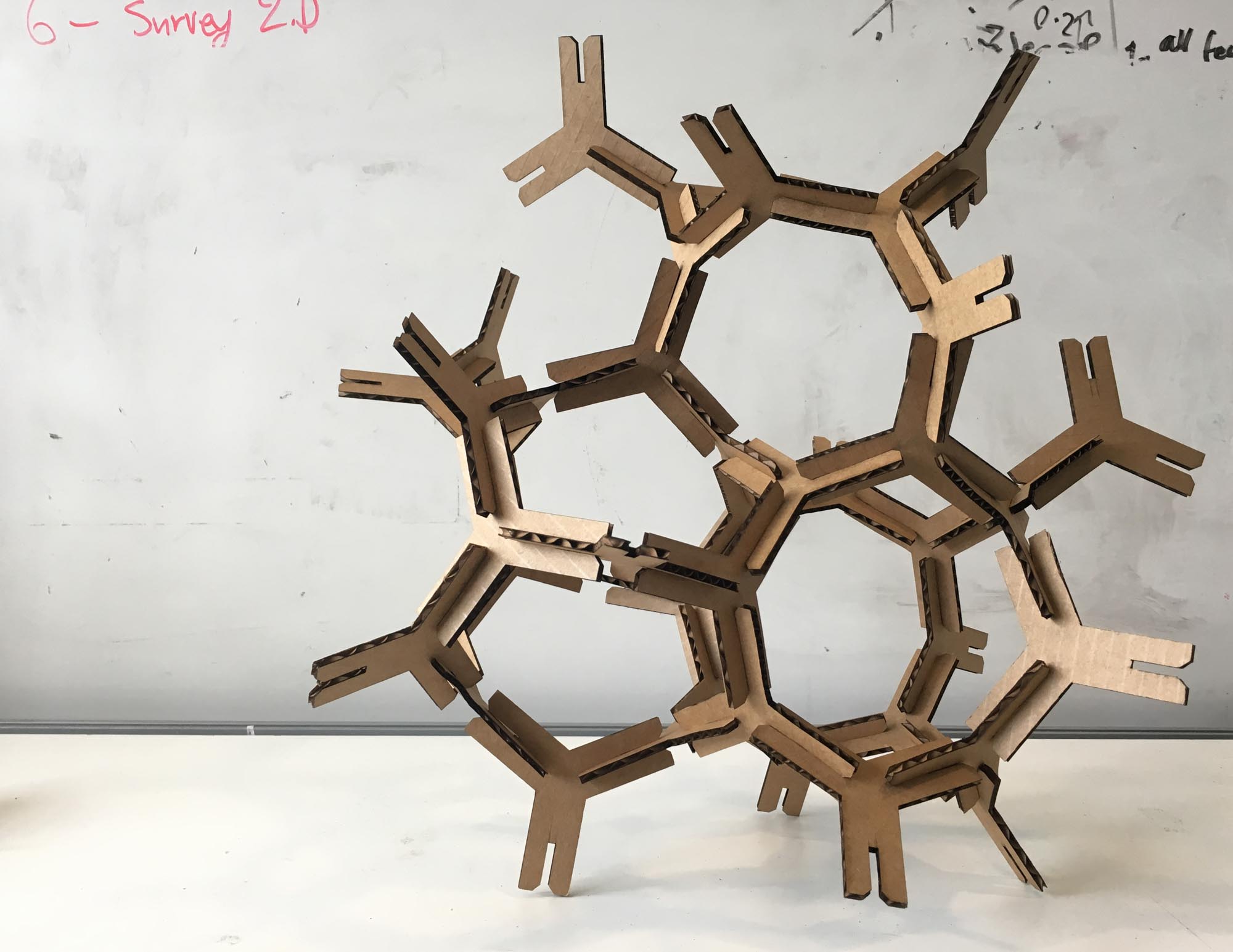
During the construction process, there are three levels of bracing to add structural support. The first level of bracing is simply two pieces interlocking together. The second level of bracing is assembling the pieces into a ring. Finally, the to get an additional level bracing, these rings can be assembled into polygons, opening up many possibilities for building spatial stuctures.
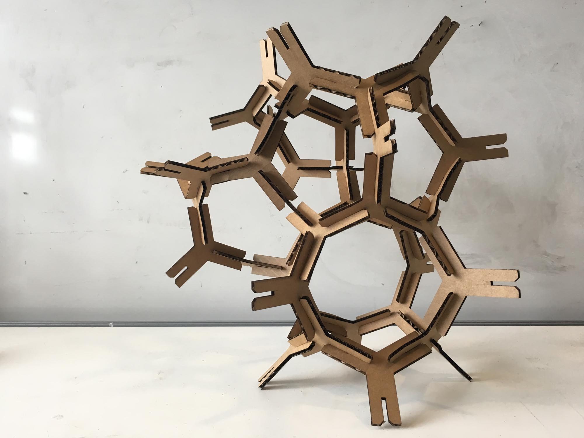
An unexpected outcome during the construction process was realizing that the stucture self-balances into a stable position as you add more pieces to the system. This effect orbits your construction in unexpected ways and changes its appearance everytime you add a piece.
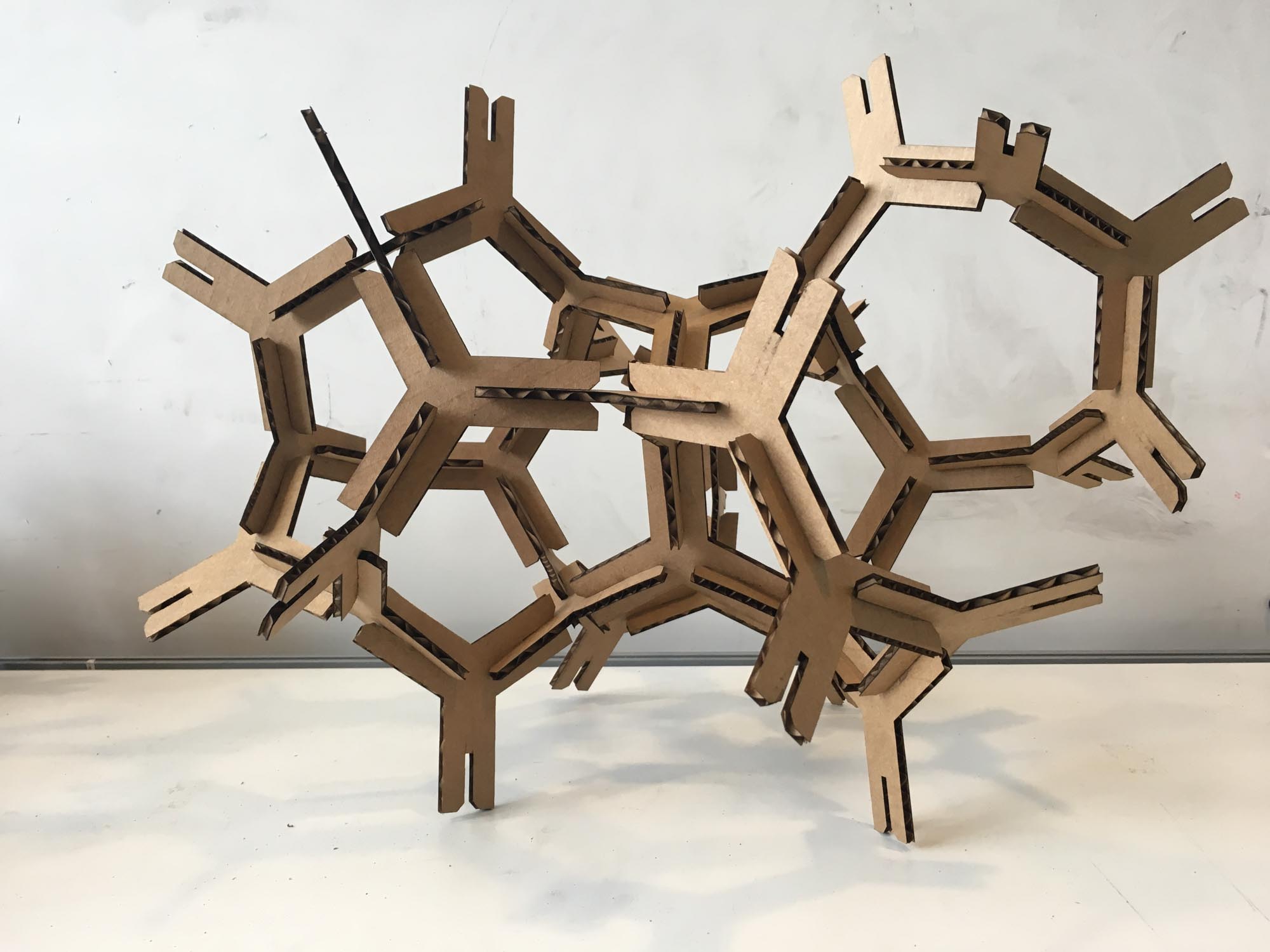
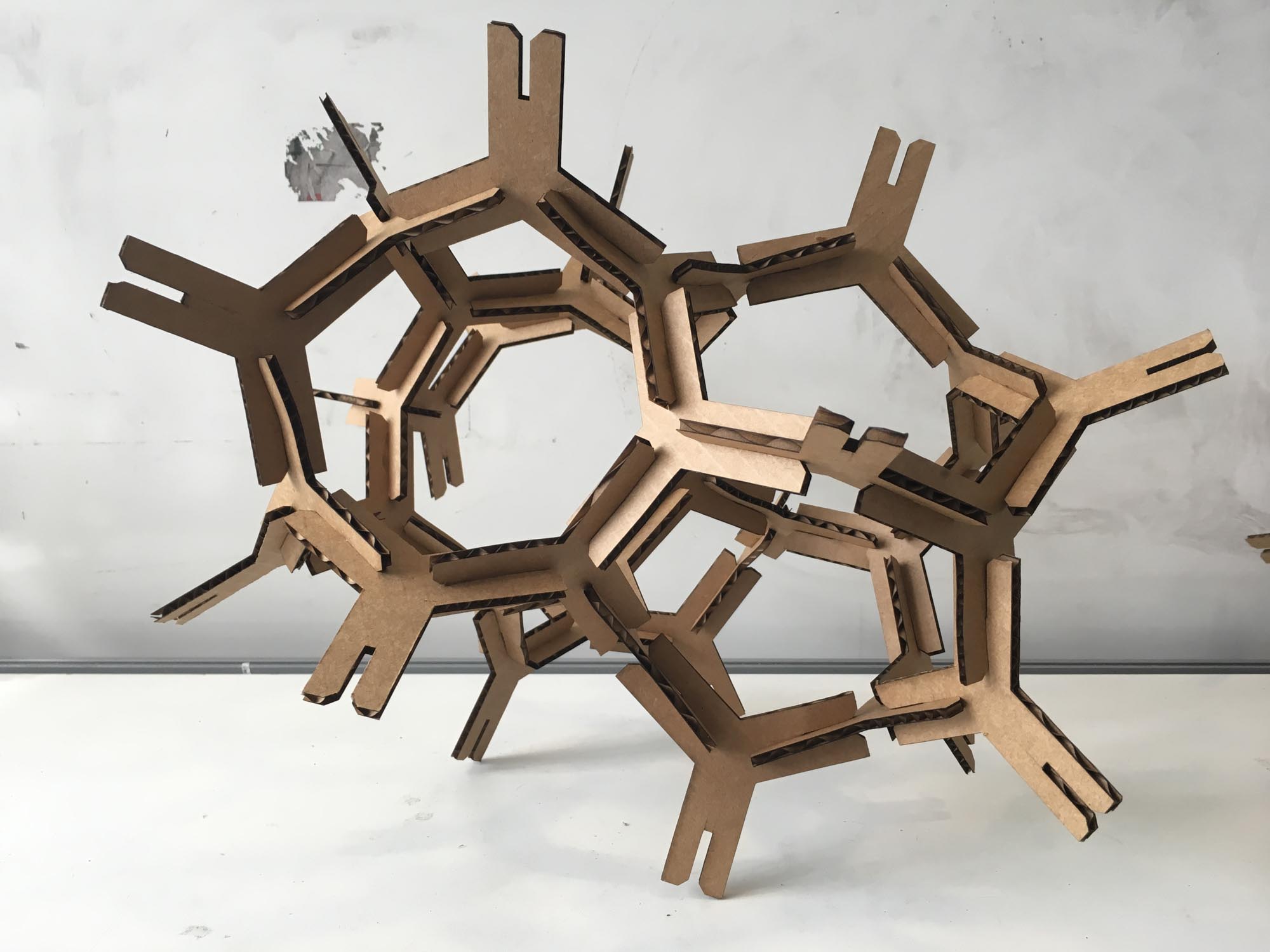
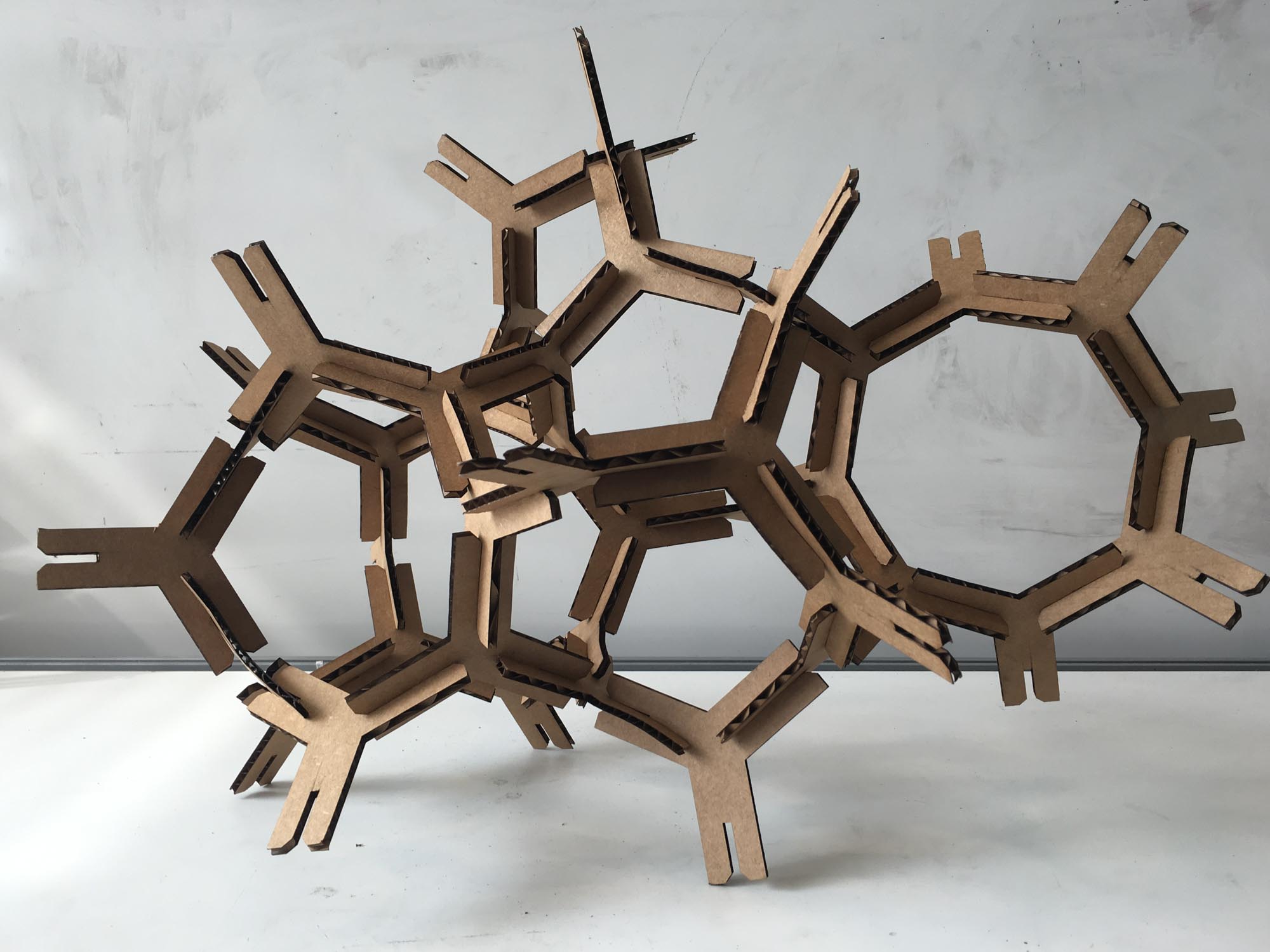
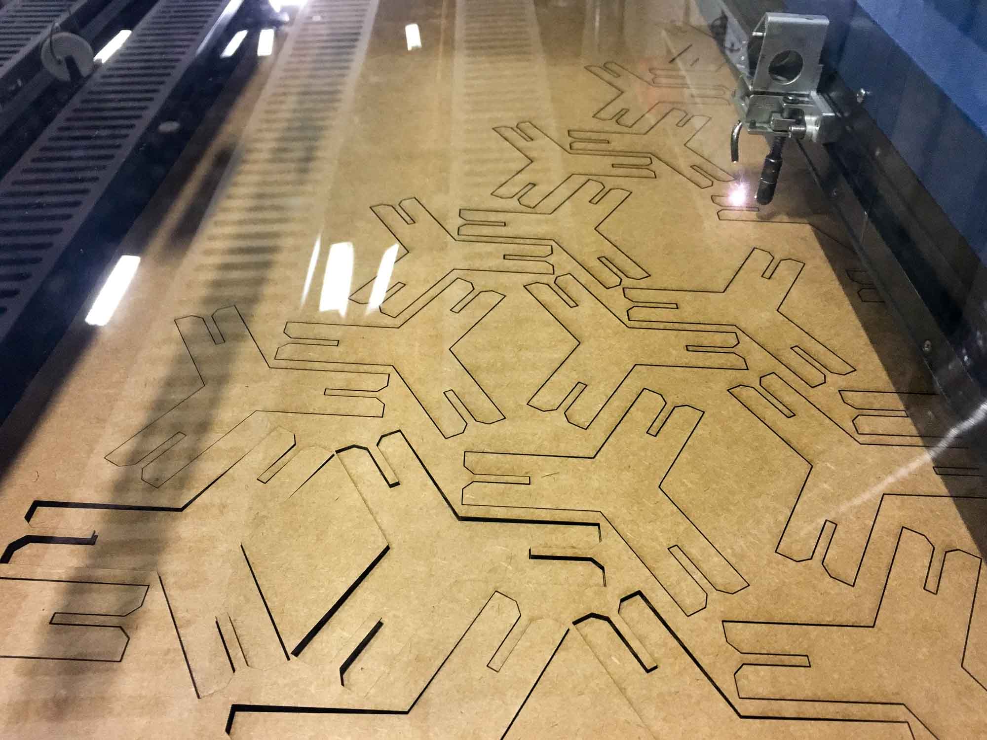
We played a while with the settings of the laser cutter, but eventually the settings that seemed to work for the 4mm micro ondulated cardboard we were using were: Speed: 20%; Power: 100%; Frequency: 200 Hz. However, I was somewhat upset with the amount of wasted cardboard in my design, so I went on to design another construction kit that tried to minimize wasted material and had more one unit to open up more possibilites for construction.
Ok, not 0, but it gets pretty close.

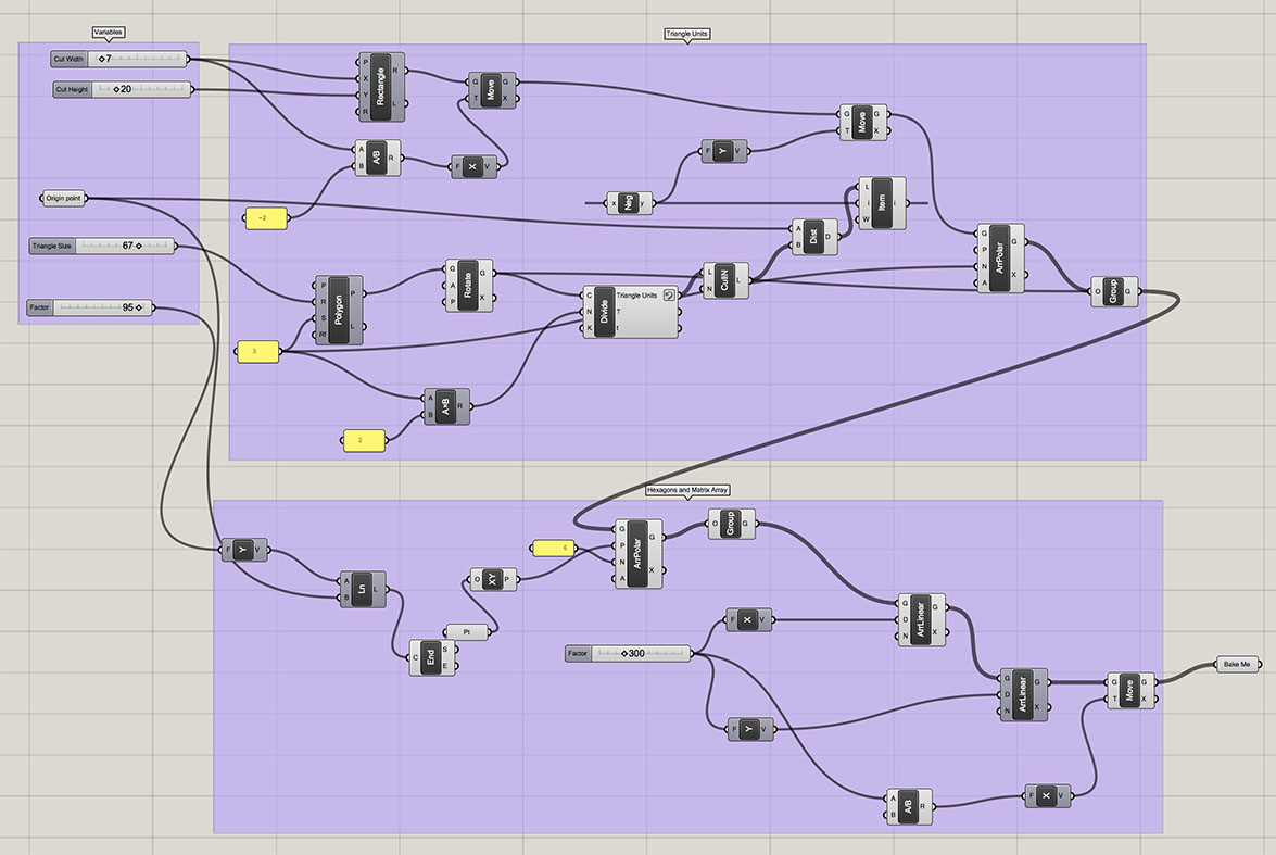
I designed the pattern in Grasshopper for Rhino and then fired it up in the laser cutter.
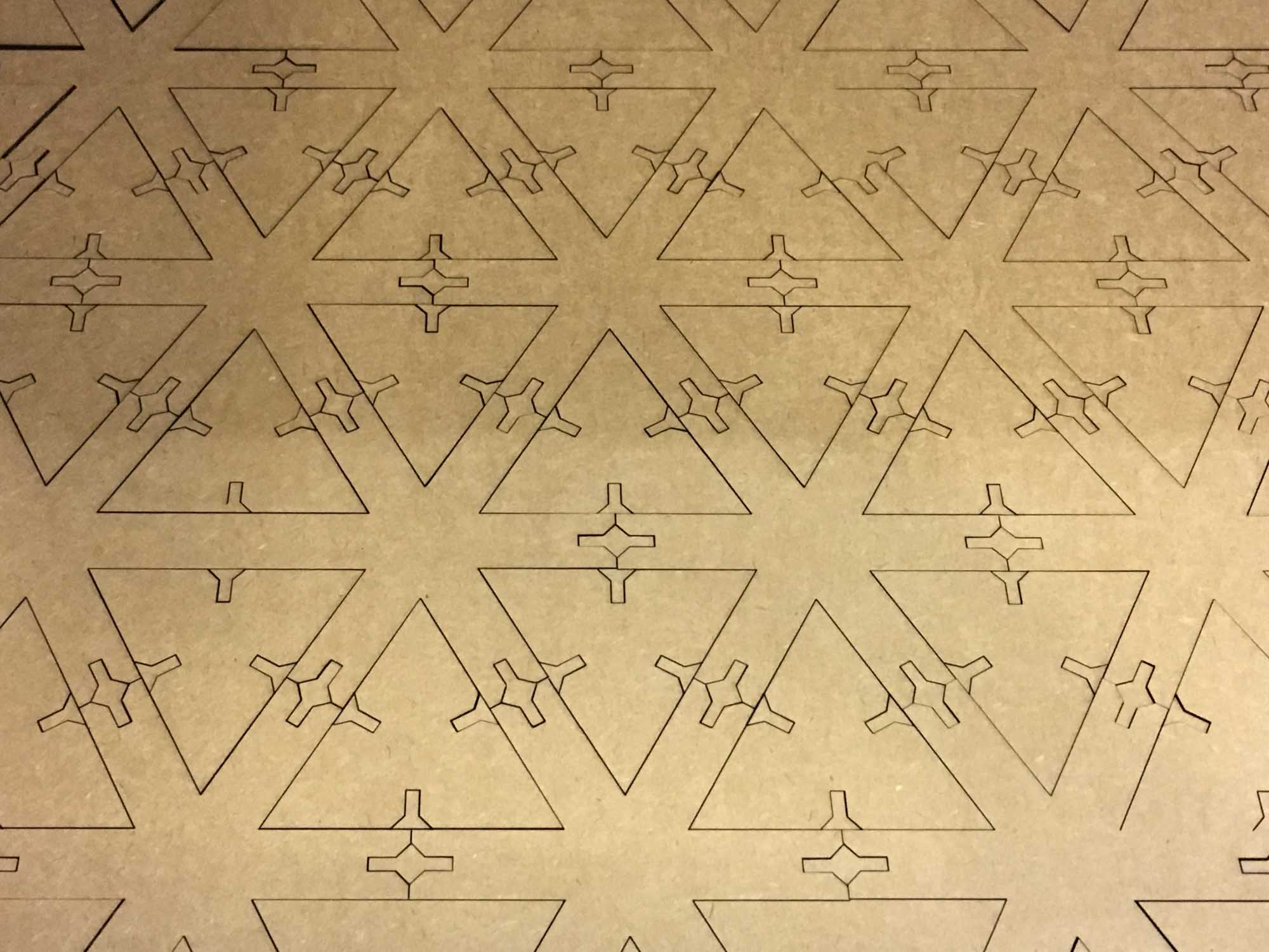
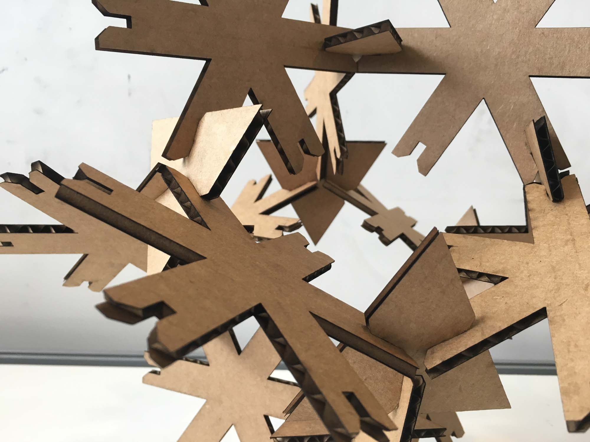
The two basic units in this design are the triangle and a 6 tip star, both with paremetrically designed joints.
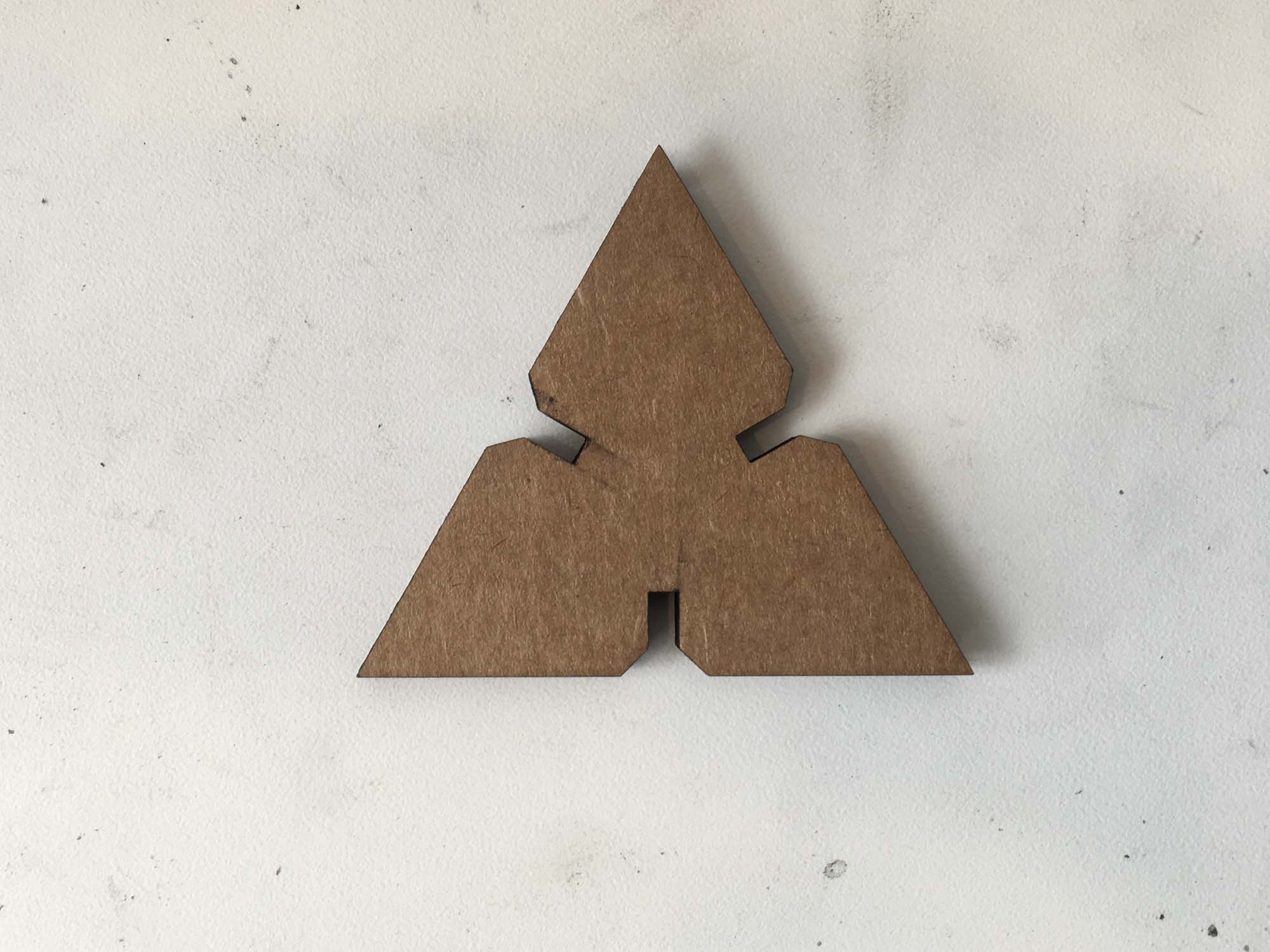
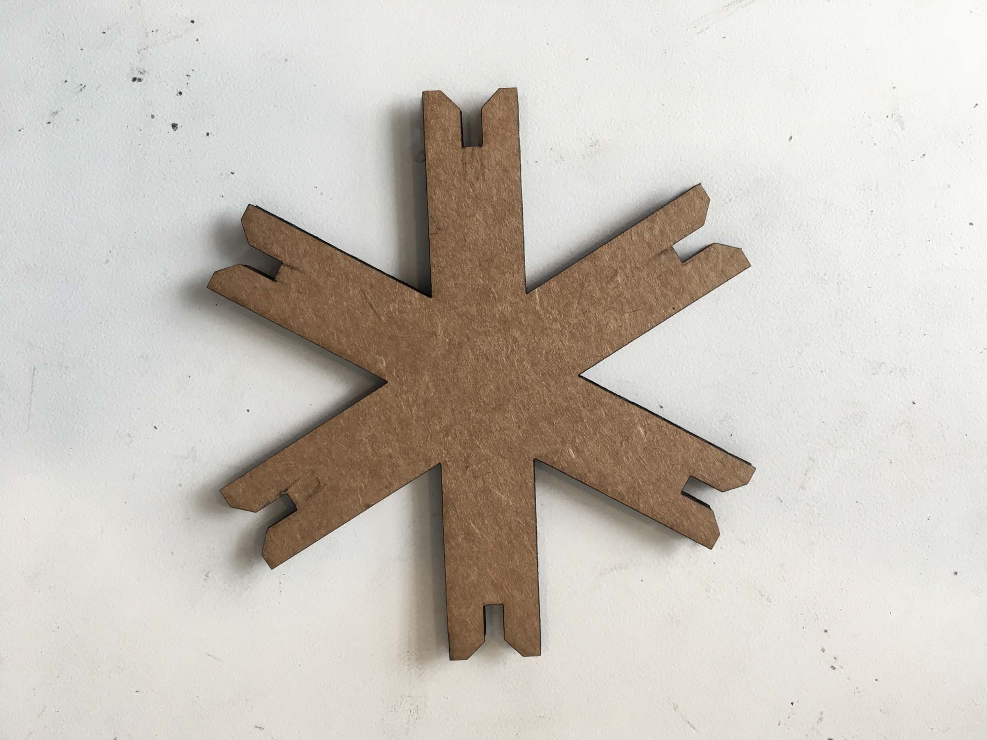
The system allows for both construction of an infinite spatial grid or freestyle construction.
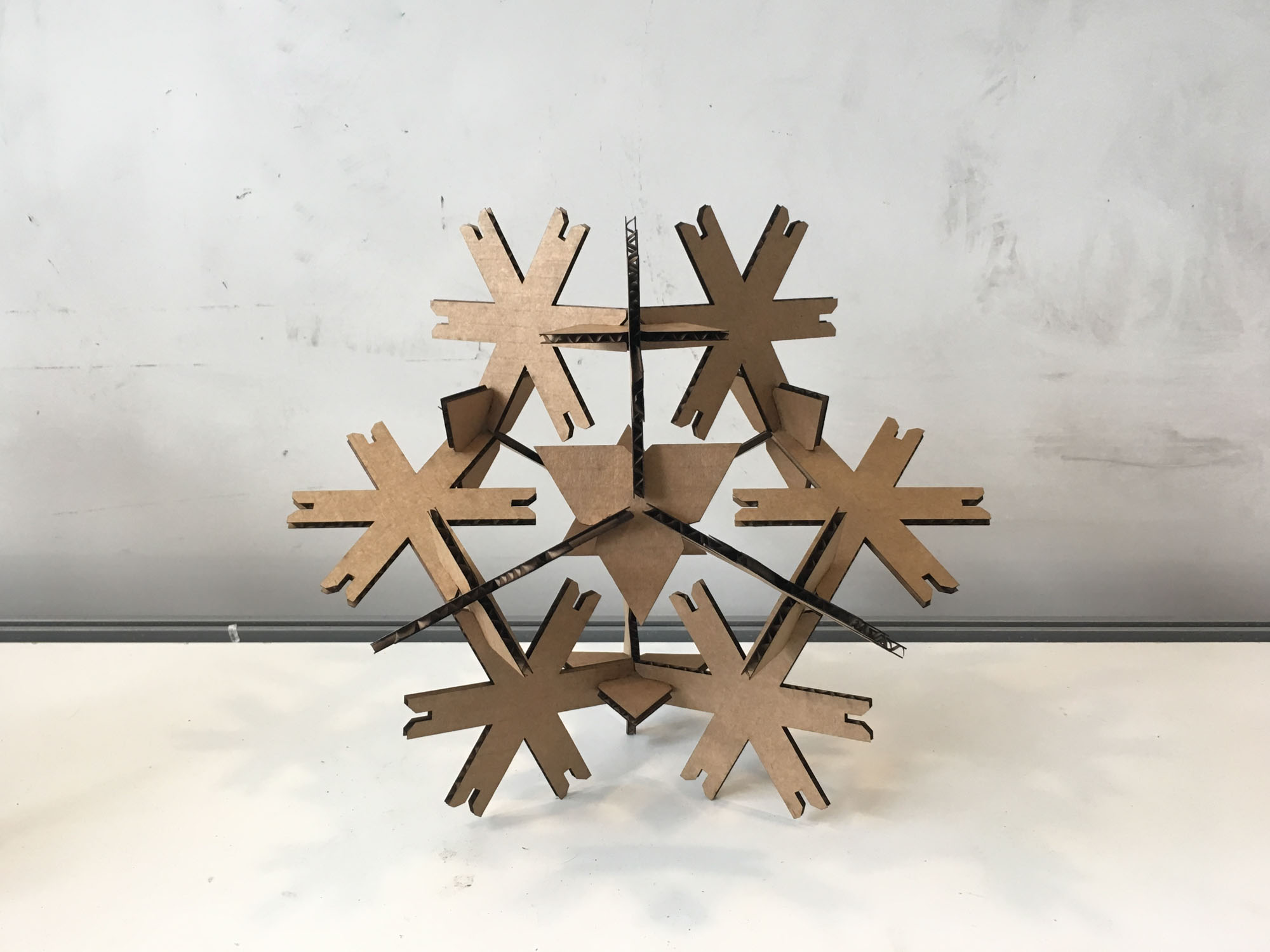
The system allows for both construction of an infinite spatial grid or freestyle construction.
Cut something on the vinyl cutter.
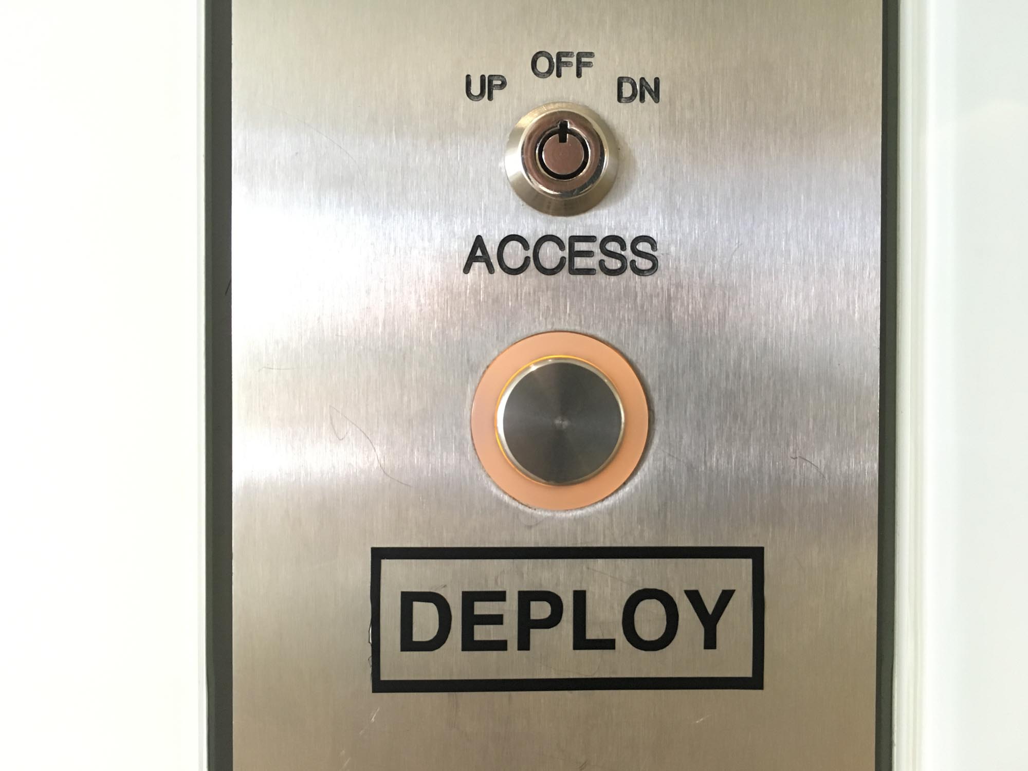
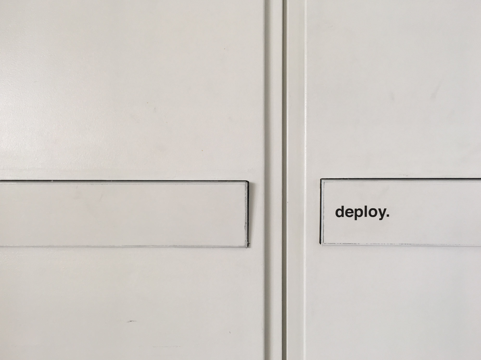
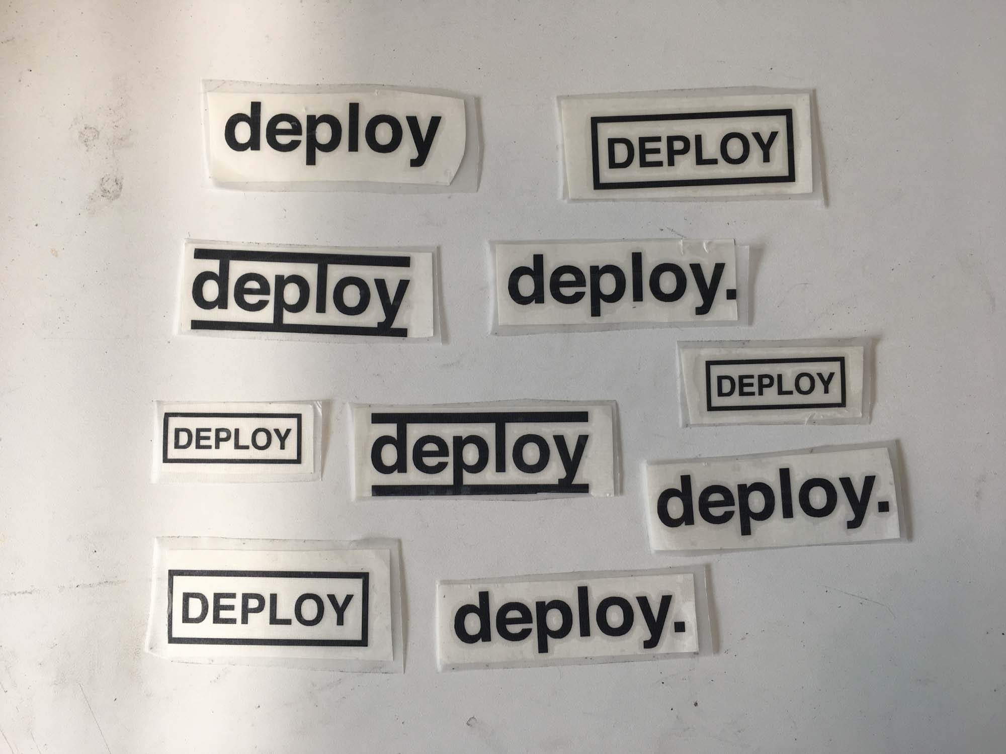
For this part of the assignment, I designed a logo for Joi Ito's Deploy or Die motto for the MIT Media Lab. I decided to drop the Or Die part, following President Obama's recommendations. Next, I proceeded to bomb the lab with stickers.
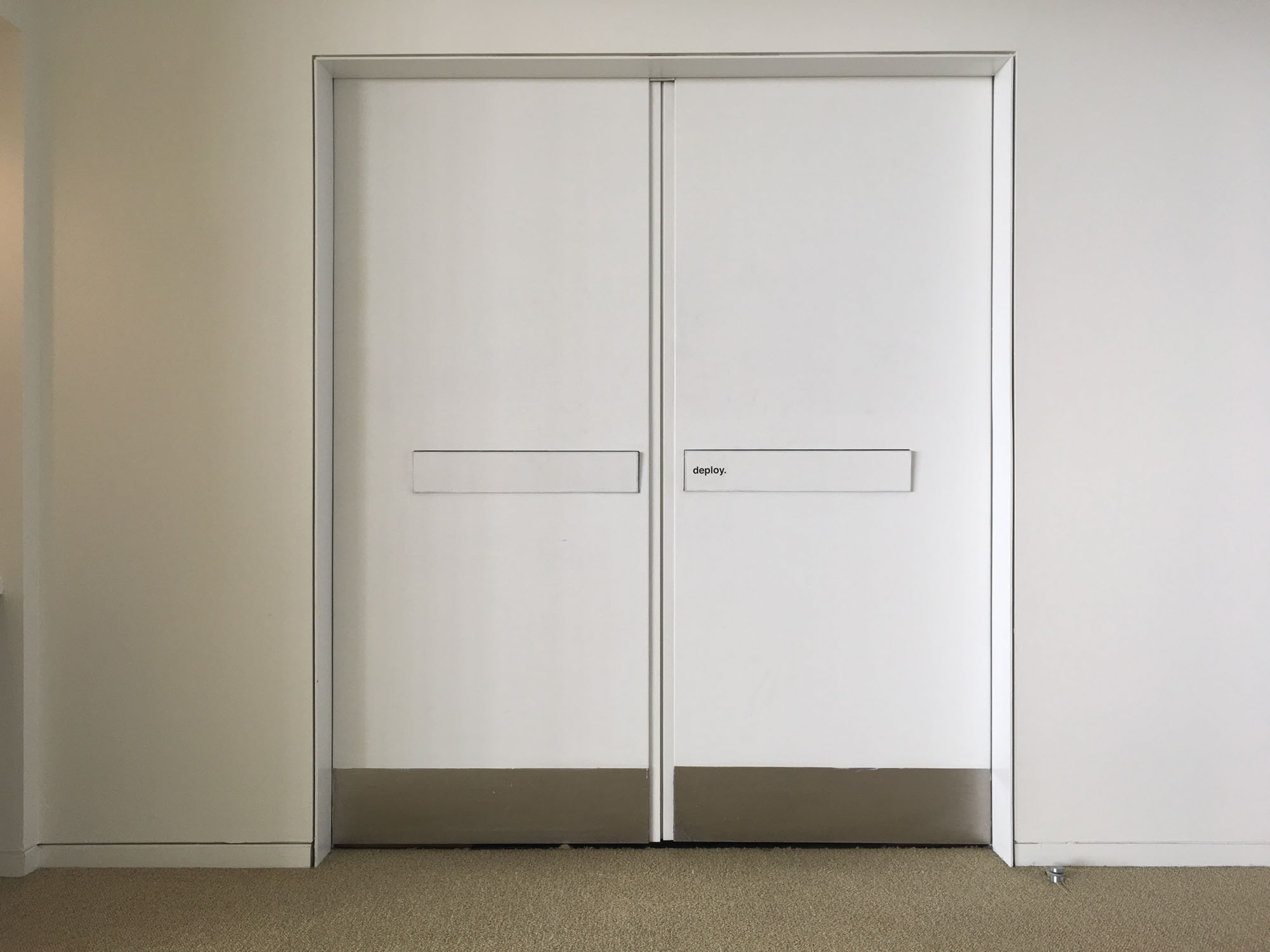
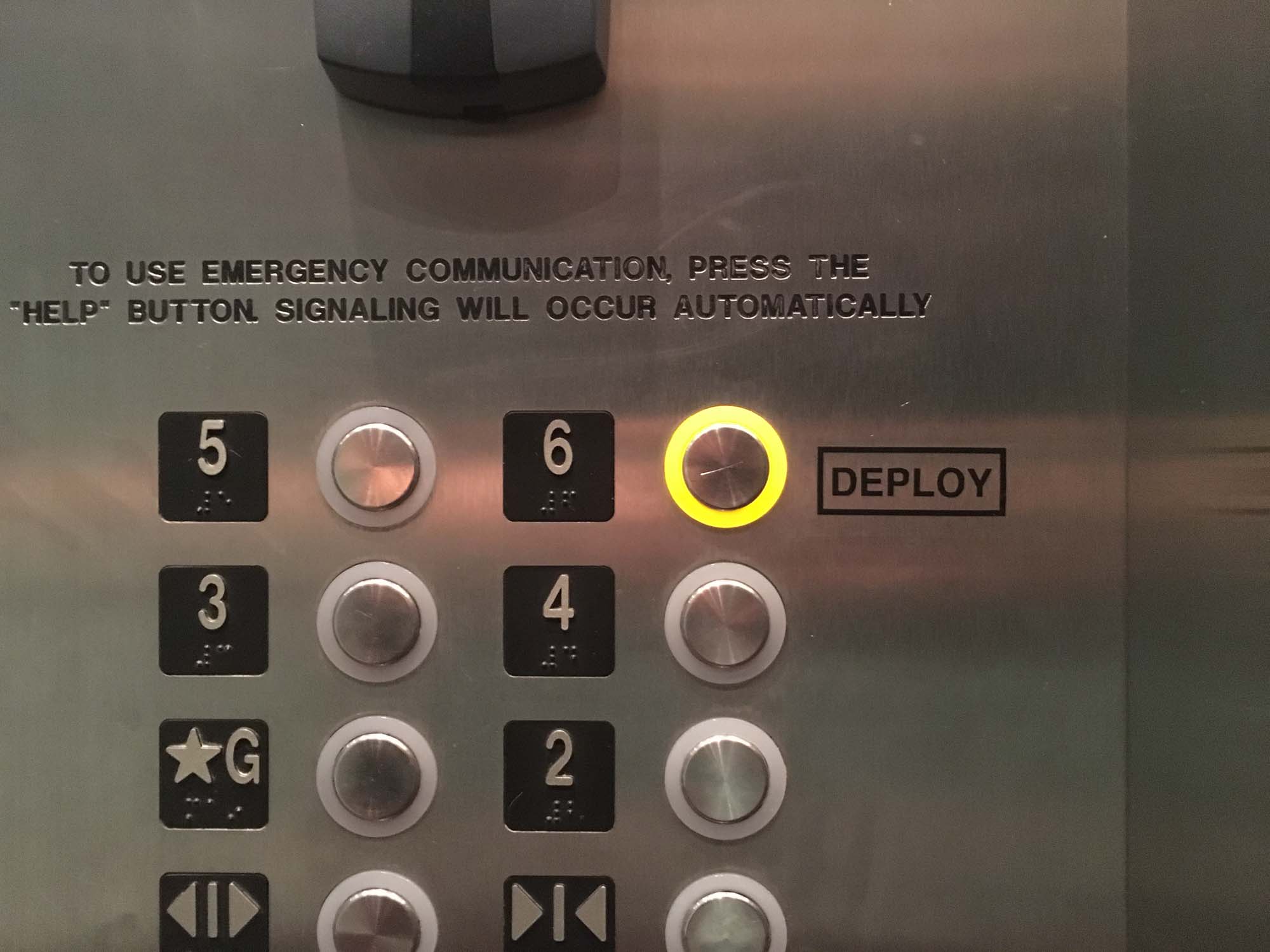
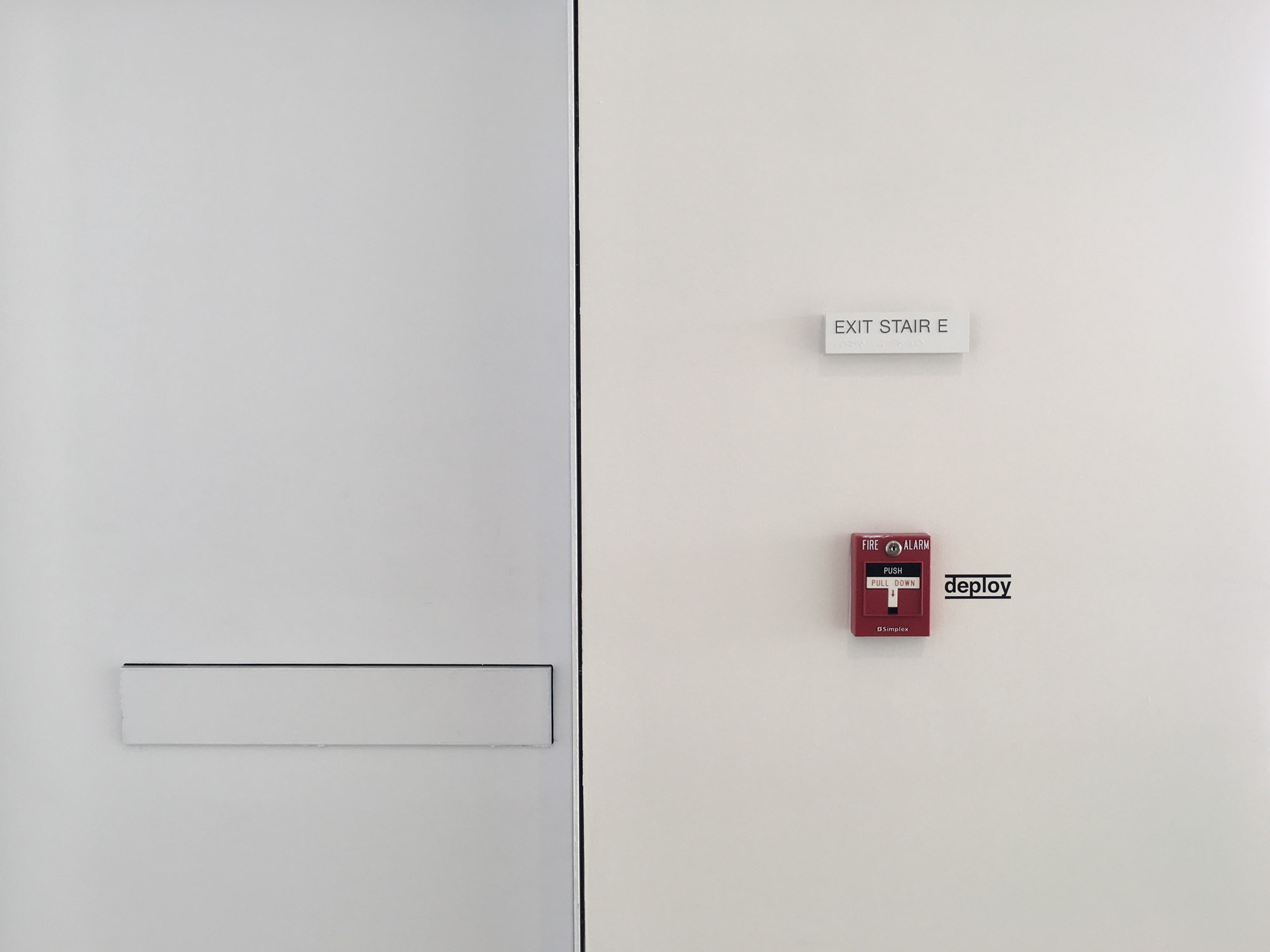
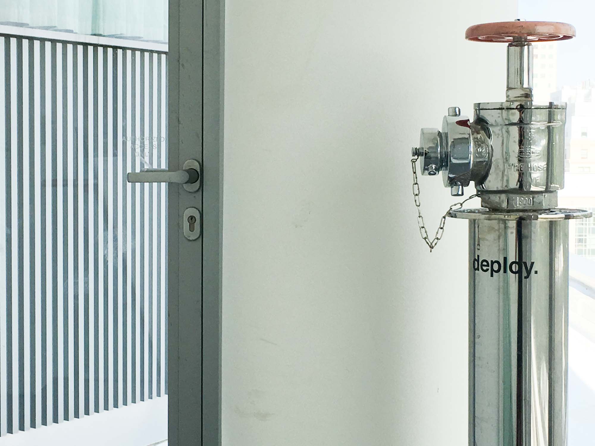
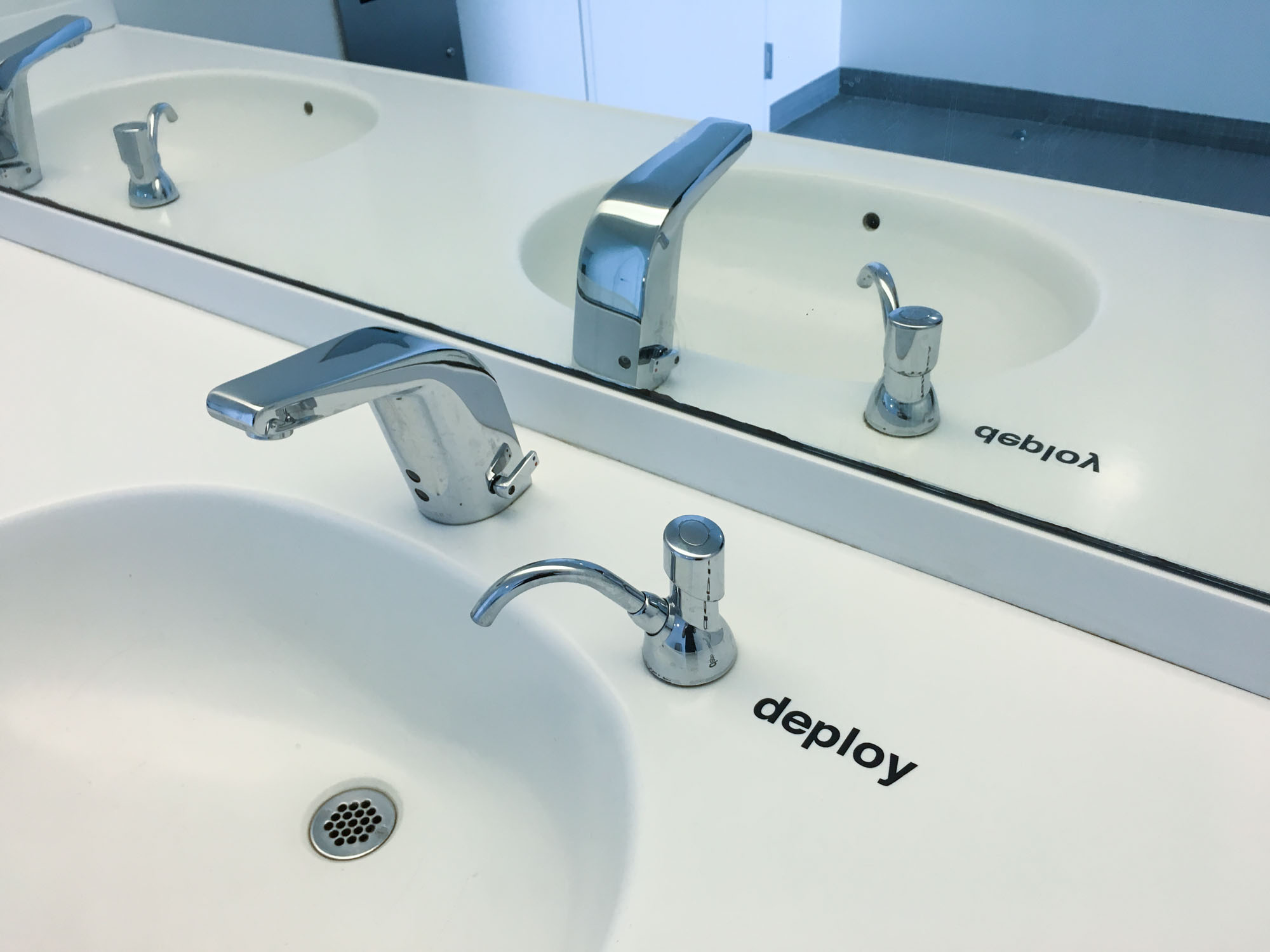
Neil mentioned in class that the vinyl cutter is generally one of the most underrecognized machines in Fab Labs, in part because they can be tricky to set up. Luckily, we had Tom to help us in the process of adjusting the height of the blade of the cutter. At the lab we are using the Roland CAMM-1 GS-24 vinyl cutter.
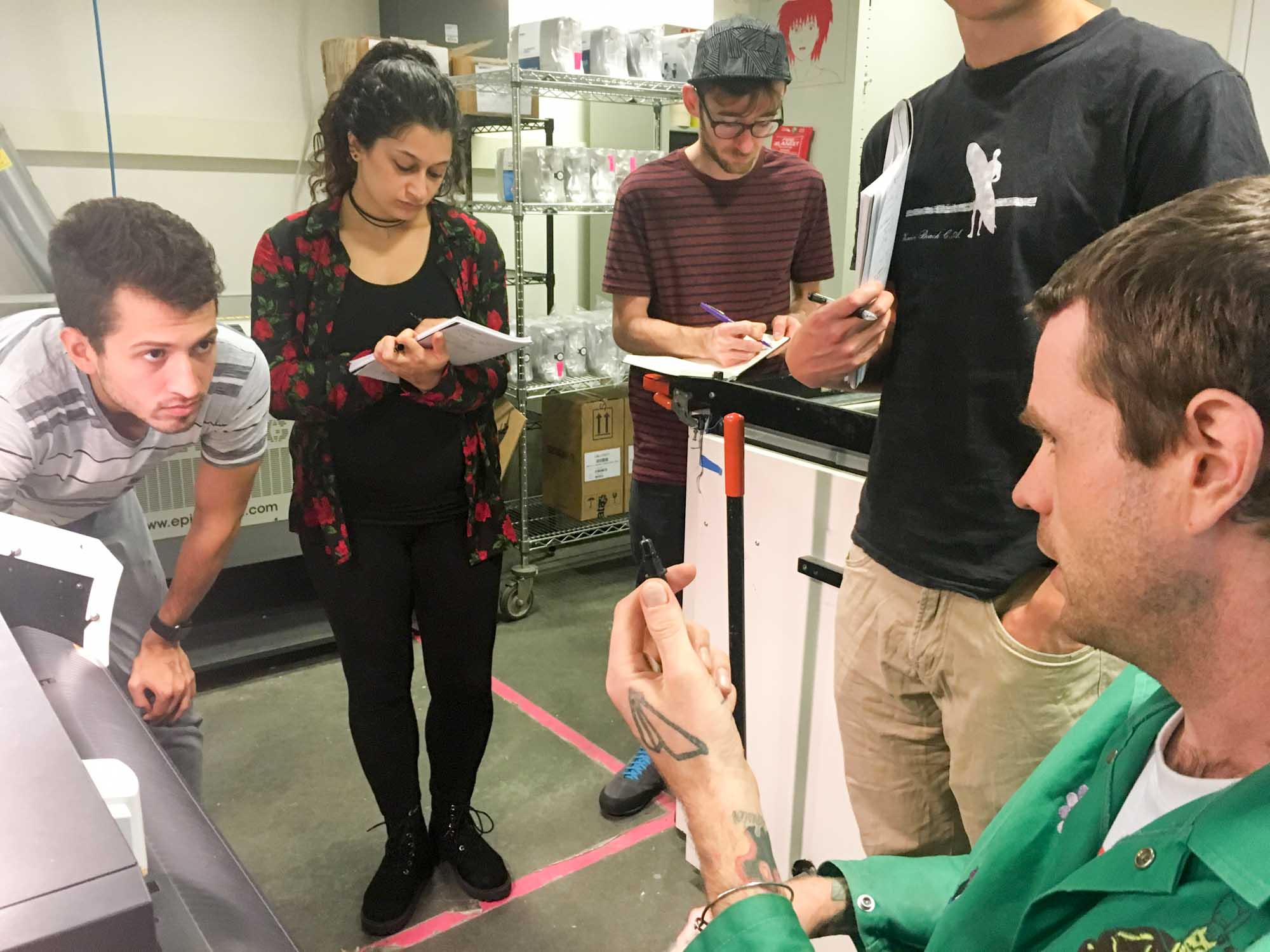
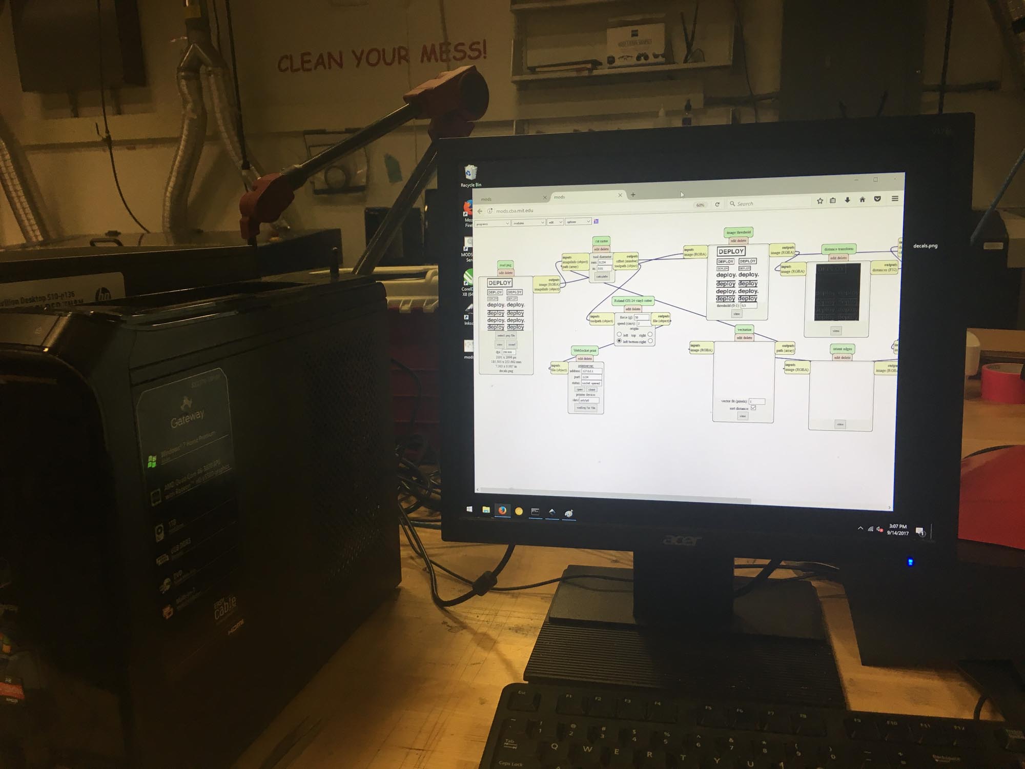
The design was done in Adobe Illustrator. The DEPLOY typography had to be vectorized before outputting the vector file (.svg) file for cutting. This was used with the Object > Expand command in illustrator. Then, I used Mods to control the vinyl cutter. To cut through the vinyl without cutting the paper underneath we used 80 for force, and a speed of 2.
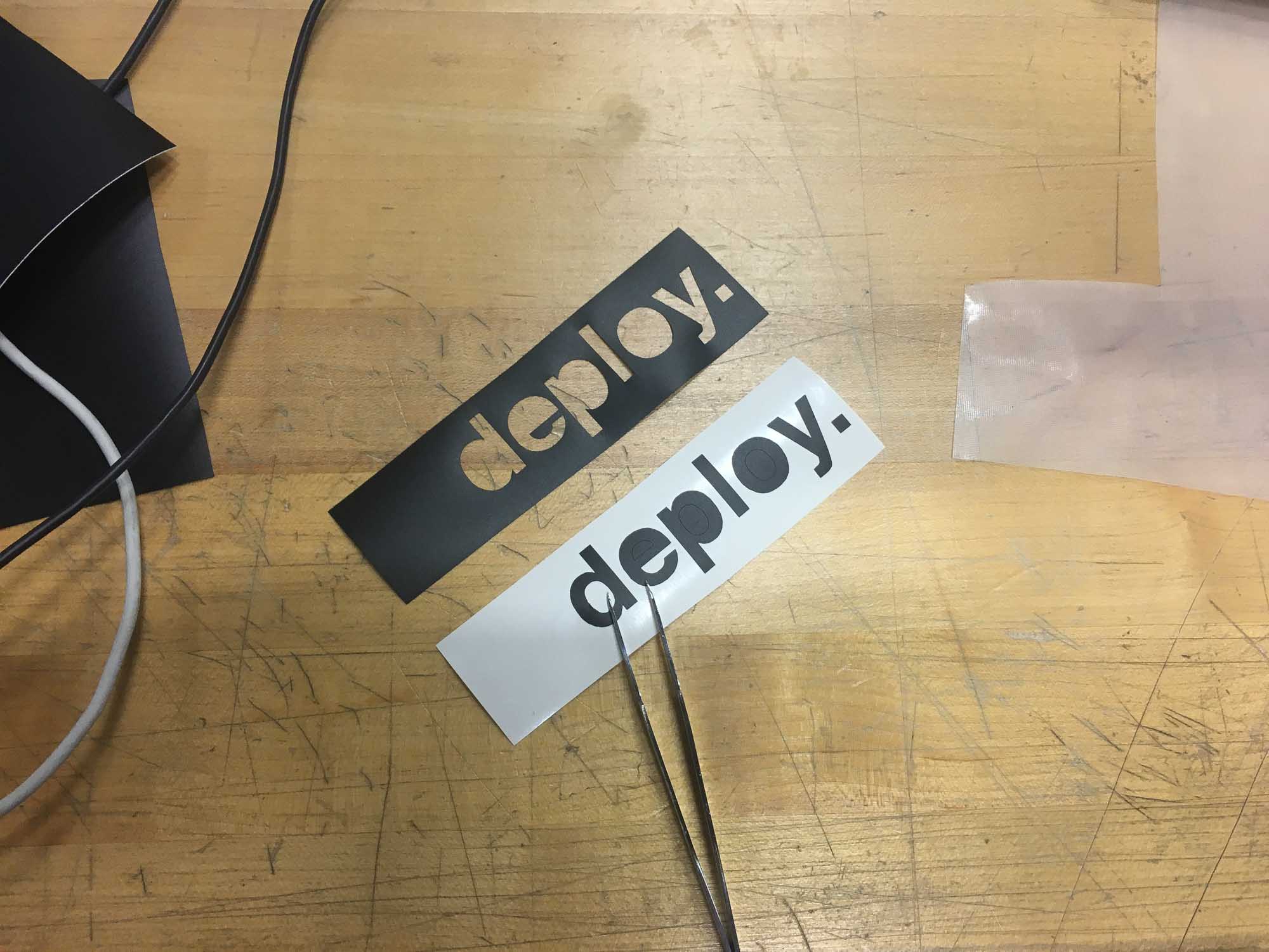
After the cuts, I need to weed out the parts that are not part of the inteded design. During the weeding process there is room for experimenting with removing parts of the original design or using for the sticker the negative of what you planned of cutting.
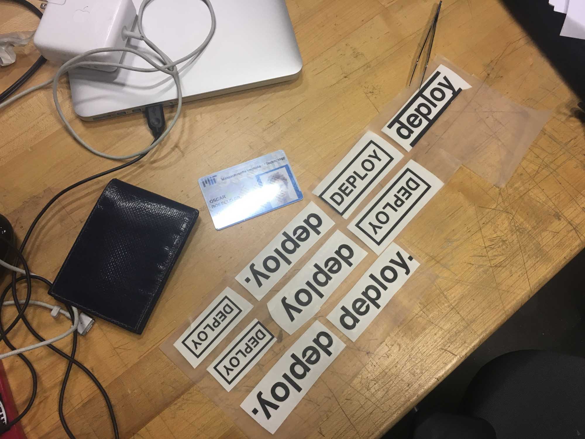
Then, I added a layer of adhesive transfer lining. Pro tip: The MIT ID makes a great improvised press tool.
Make an in-circuit programmer by milling the PCB.
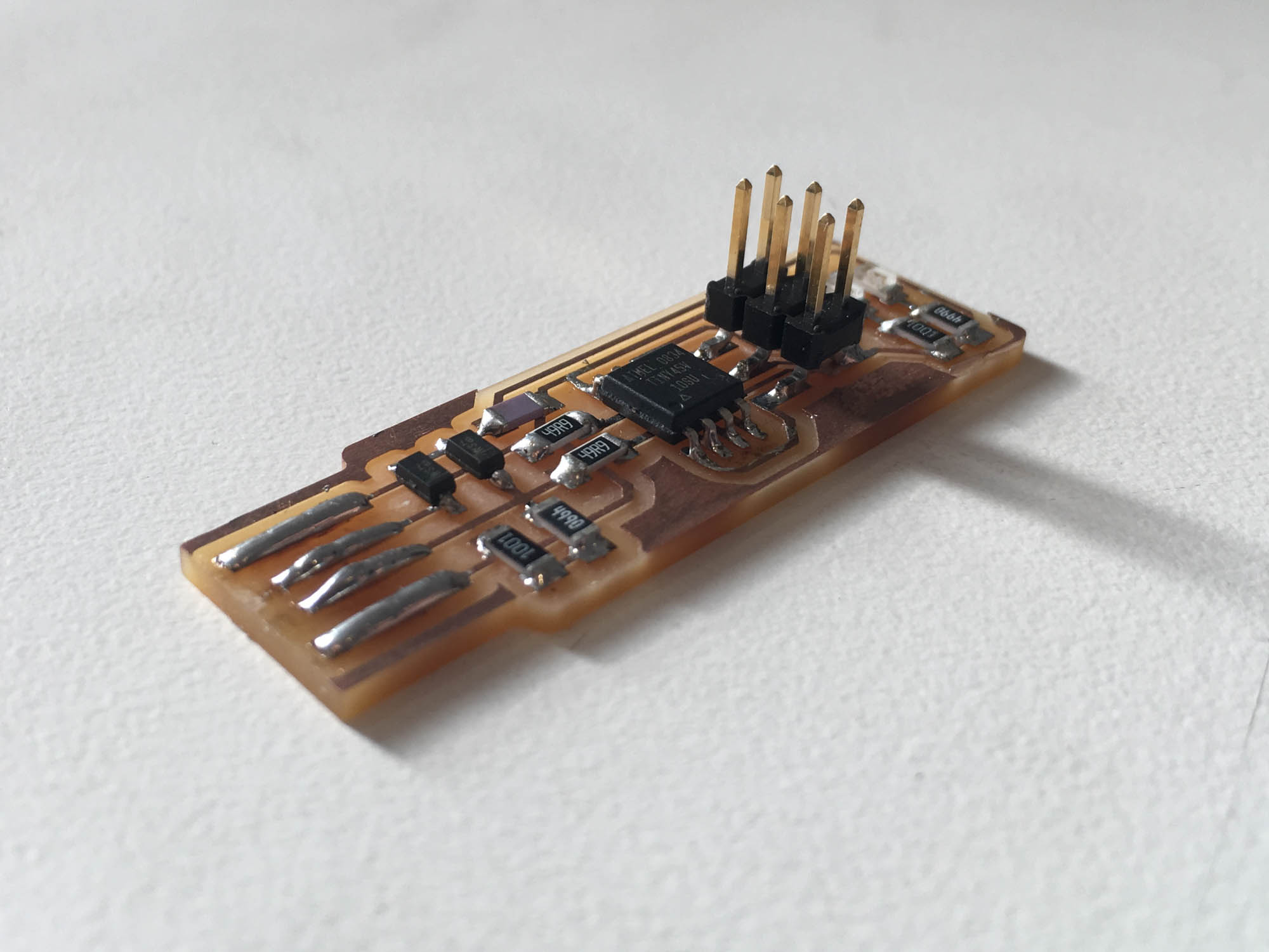
This week we are making our own AV in-system programmer (ISP) board. For this project, I followed Brian's guidelines for fabricating the FabTinyStar, a low-cost ISP that can be built in the fab lab.
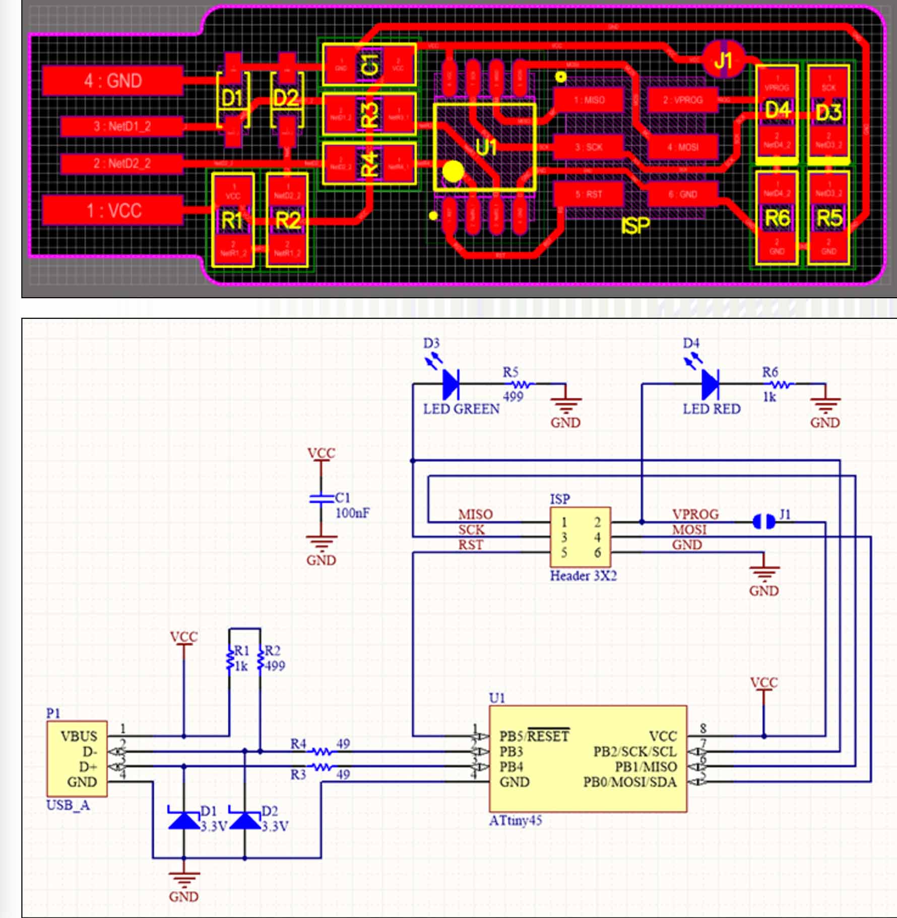
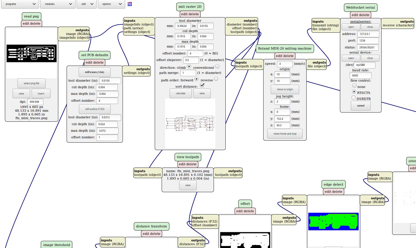
First, I milled the board with the Roland Modela MDX-20, a desktop precision milling machine. We are using PNG image files as the source file for the traces and outline of the board, controlled my Mods. Mods takes the raster information from the image file, takes in the user input and applies image processing to extract the machine paths. I used 1000 dpi for export to make sure the paths were as accurate as possible.
Next, I secured the board to the machine to make sure the vibration was not affecting the quality of the milled paths. A useful tip is using plenty of double-sided tape along the longitudinal edge of the board instead of clamping the board into the machine.
The next step is zeroing the machine to make sure the origin of the board we used. Note that the machine takes the bottom lefthand corner as the origin.
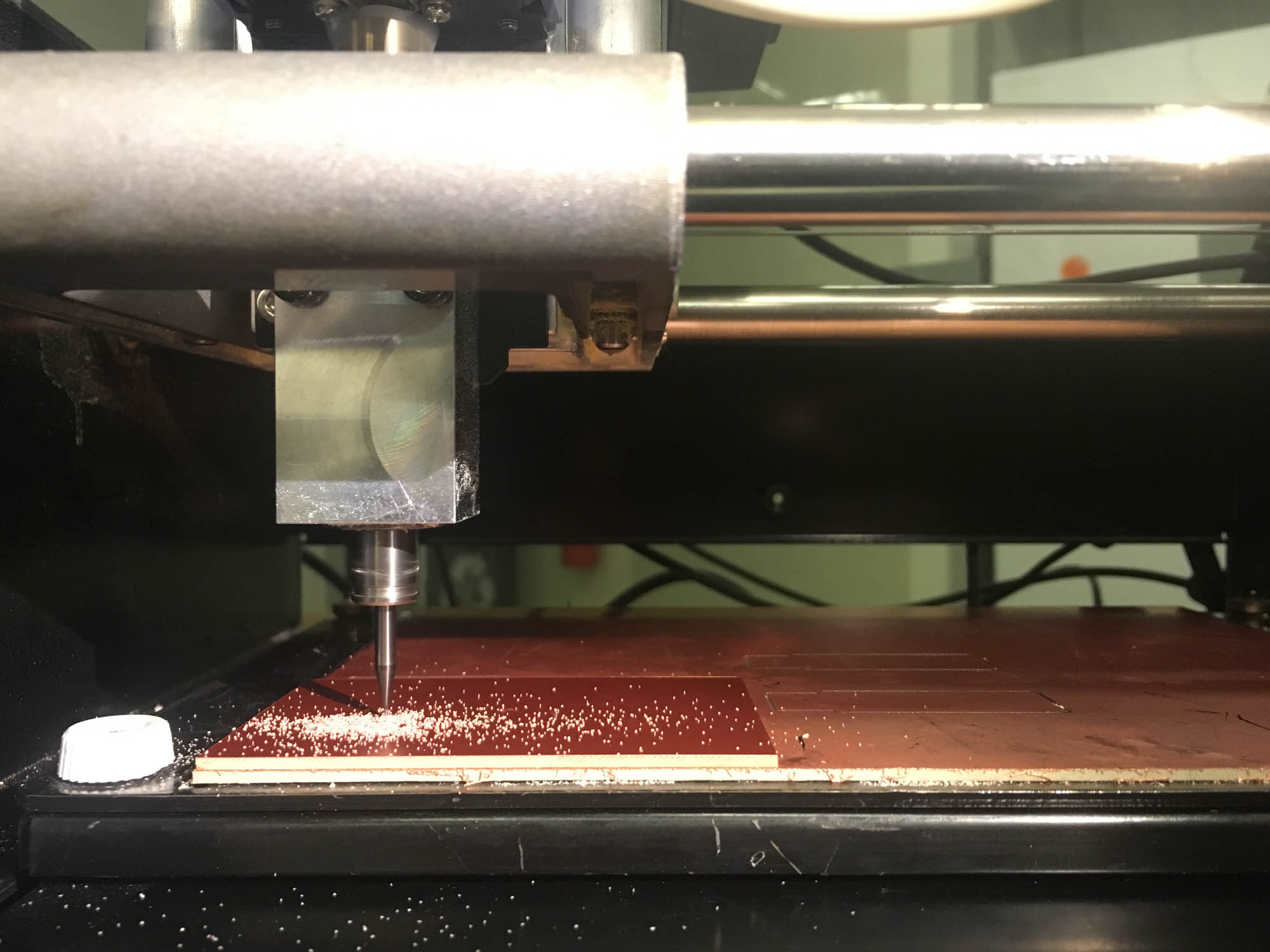
The milling is done in two passes, that correspond to two different end mills and settings. The first pass is done using the 1/64 inch end mill for the traces. This step removes all the material that is colored black on the PNG. The second pass is done with the 1/32 inch end mill, and mods is adjusted to cut throughout all the material that is not white. The order of the passes matters, because cutting the traces first prevents the board from shaking when cutting the holes that go through.
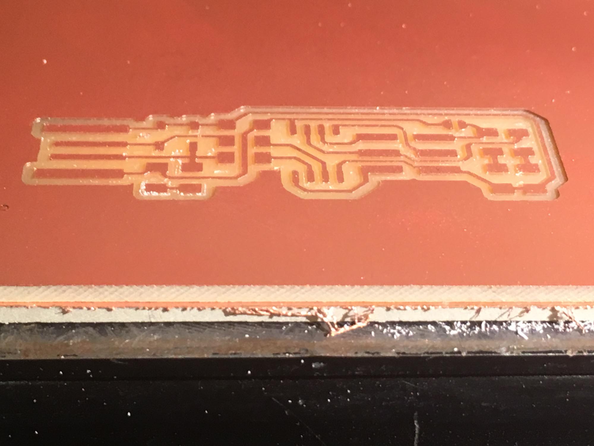
Once I milled the boards, I gently sanded it with fine sanding paper to make sure the top is perfectly flat. Then, I washed it with isopropanol to remove any excess oil left from handling the board.
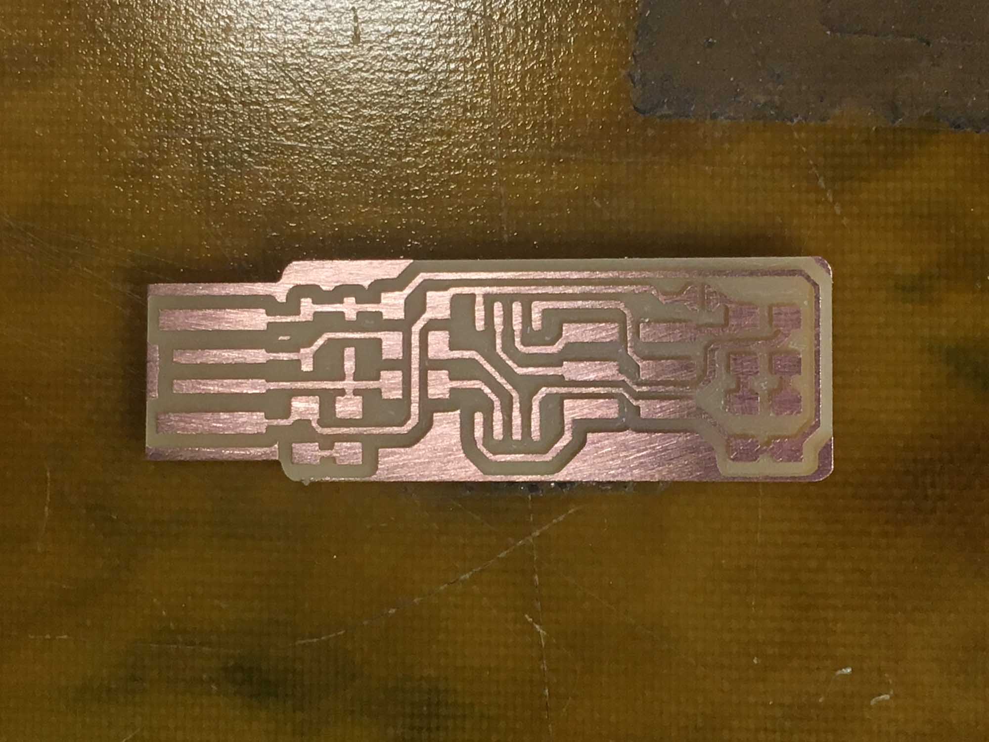
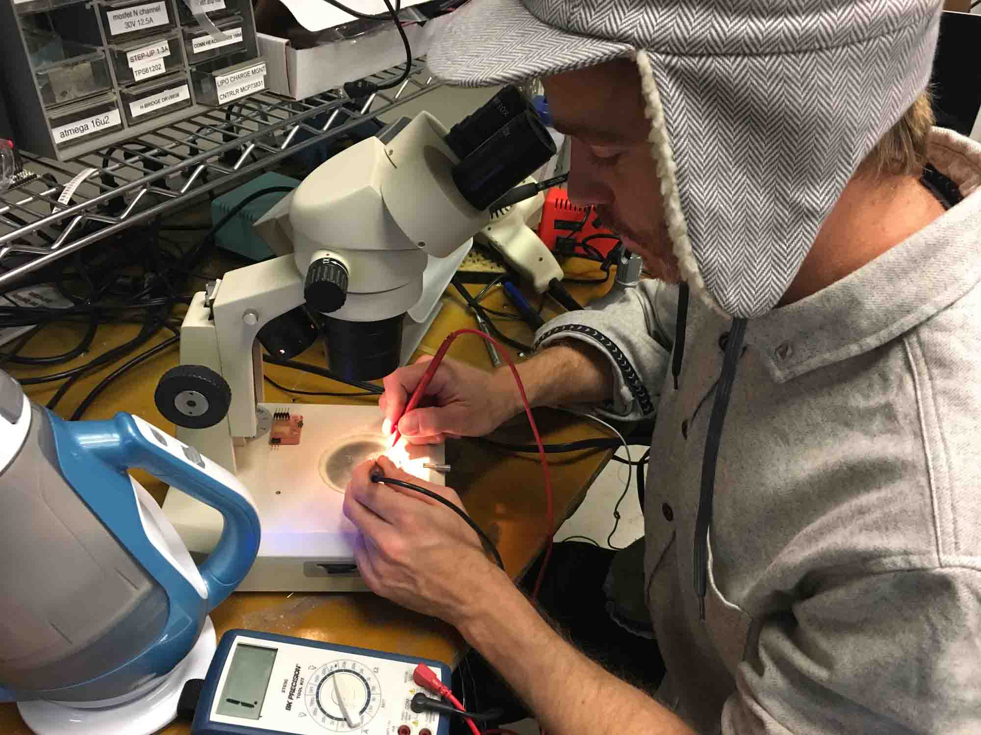
Next step was stuffing the board with components. The board and components are extremely tiny, so soldering them on the board can be quite a challenge. The first step when soldering is adding a thin coat of solder to one of the pads. Then, with a pair of tweezers, we place the component on the pad and warm up the solder on the pad to secure the component. Then, we apply another blob of solder to the opposed side.After the board is stuffed I checked for shorts between VCC and GND using the multimeter.
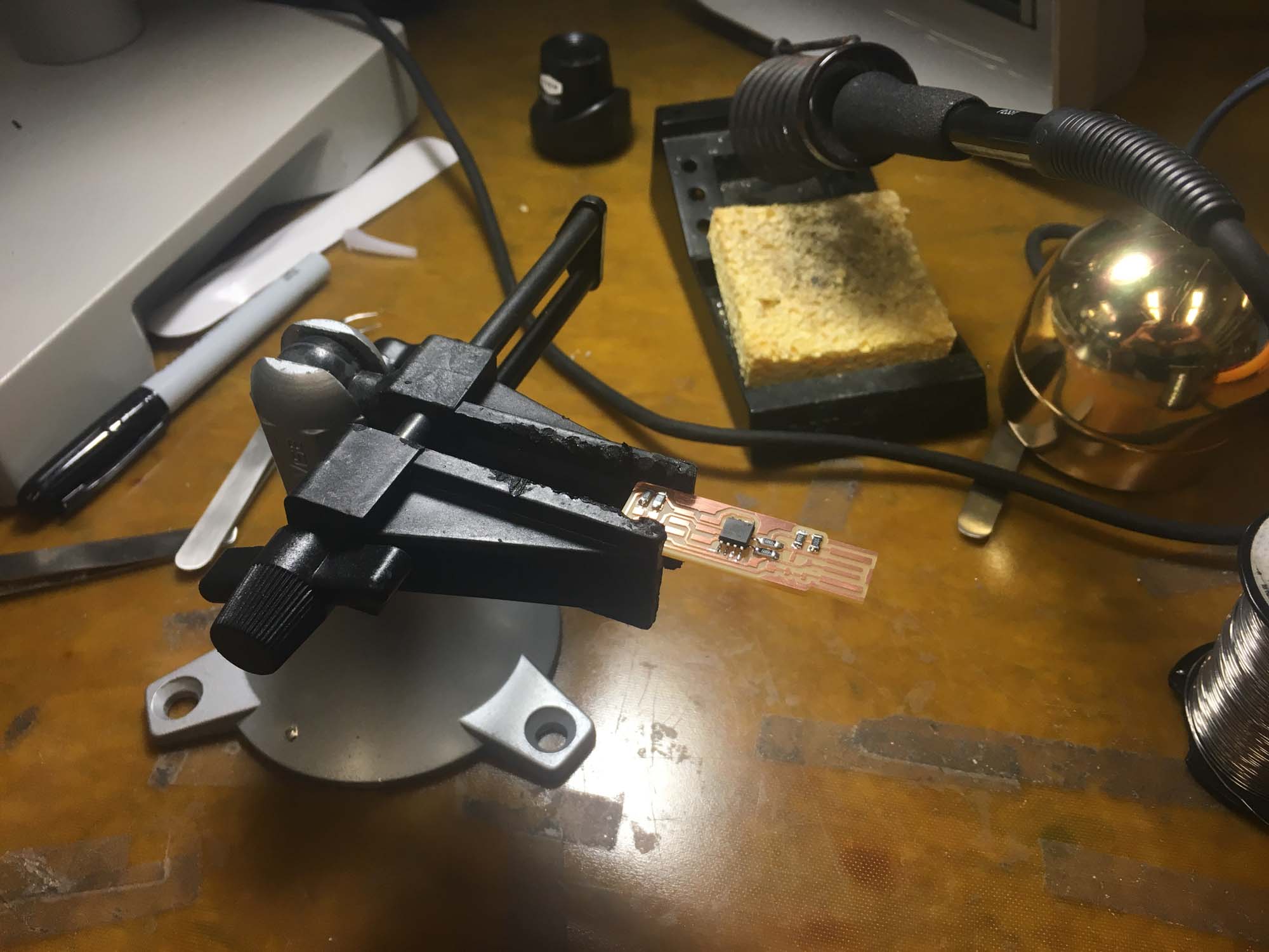
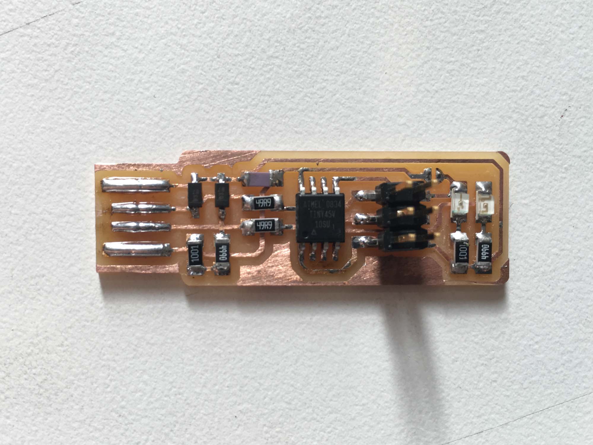
Here you can see all the components soldered onto the board, next step is programming the PCB.
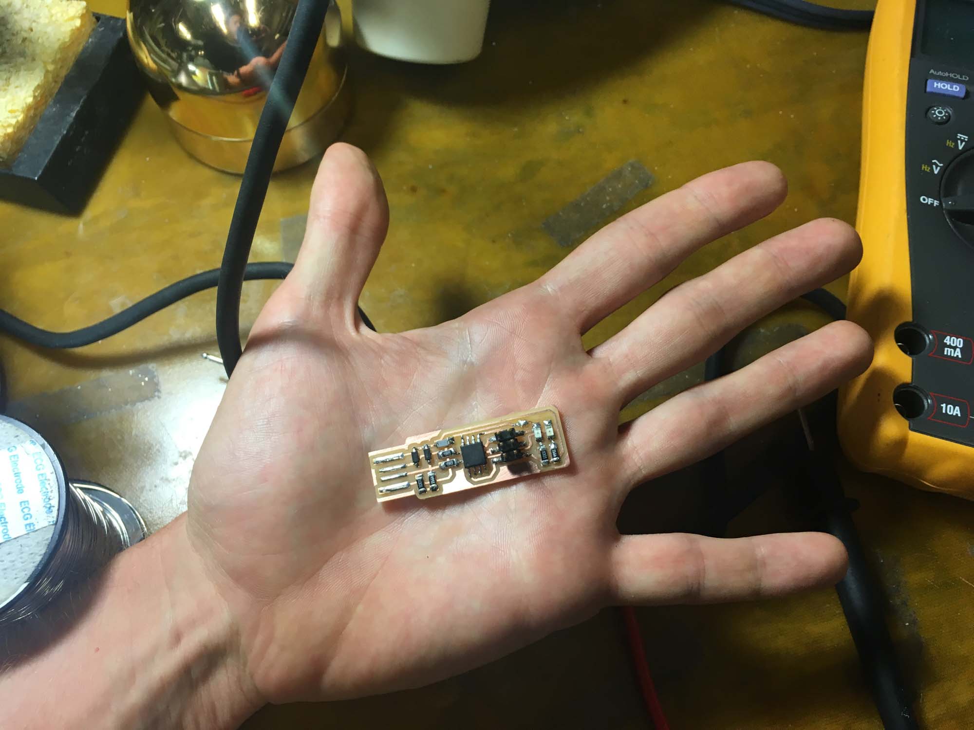
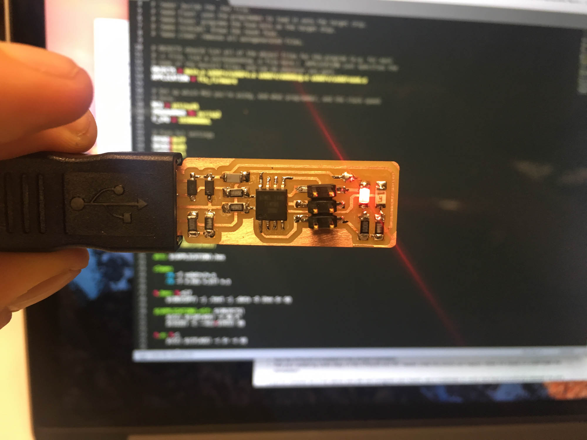
Then, I installed CrossPack to set up AVR programming. After, I installed the firmware source code and ran the 'make' command to build the hex file that will get programmed onto the ATtiny45. Next, I used the blue AVR programmer to program my board. After plugging in the board, I was happy to see the red led was lighting up.
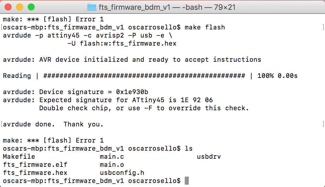
But then, when trying to program the board using 'make flash' the system kept throwing an error. I went back and started debugging. Fist step was inspecting the board visually: everything seemed to be ok. Then, I checked each component to make sure the soldering job was fine: I ended up reinforcing a couple of joints and tested again. The error was still there.
At this point, I wasn't sure how to proceed. So, following Patrick Winston's life advice, when you can't find an answer for a problem, ask someone who knows. So, I asked Tomás for help. He was extremely helpful in running the hardware debugging process together and the problem ended up being that I was using the wrong AVR microcontroller! I soldered on the ATtiny85 instead of the ATtiny55. Lesson learned, keep your workspace clean and double check your parts before you solder them on.
To remove the ATtiny85, I used the hot air gun to melt the solder from the 6 pins simultaneously and to be able to remove the part. Then, I had to use the wick to remove excess solder and then replace the component.
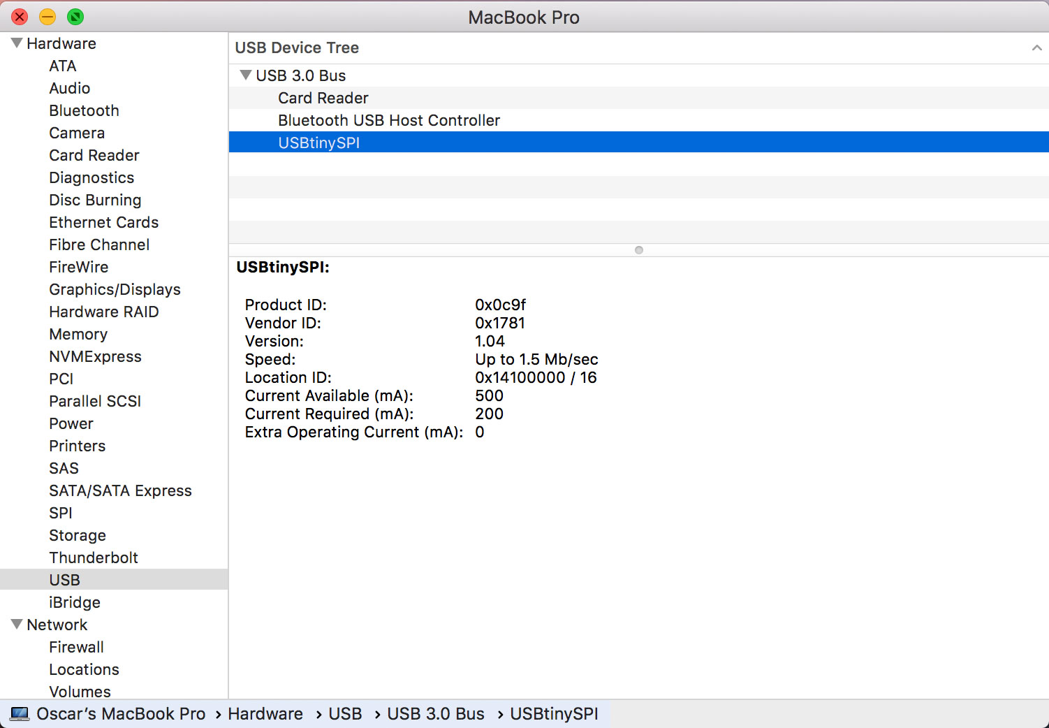
With the correct microcontroller, programming the board was straight forward. I ran the 'make flash' and 'make fuses' once again and then the OS detected the board without any problem.
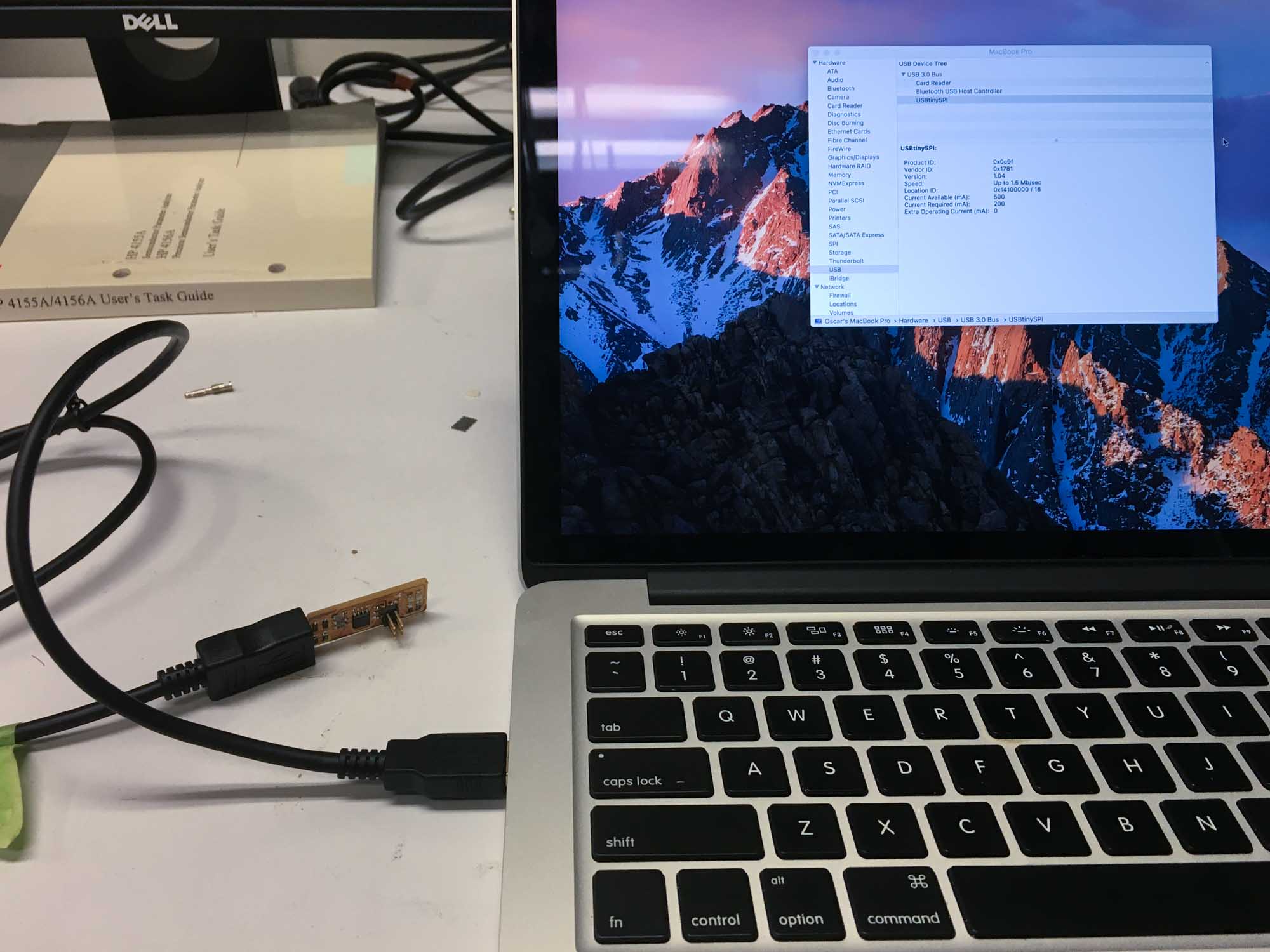
Once everything was working, the last step was disabling the ability to reporgram the ATtiny45 by blowing the fuse on the board. The ISP is now ready to program other boards!
Design and 3D print an object (small, few cm) that could not be made subtractively
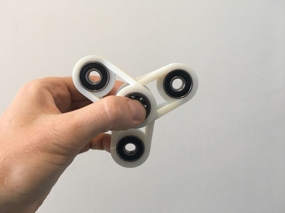
This week I made my very own version of the toy of the year: the fidget spinner. In fact, I don’t really understand why they are so popular, so I decided to build my own.
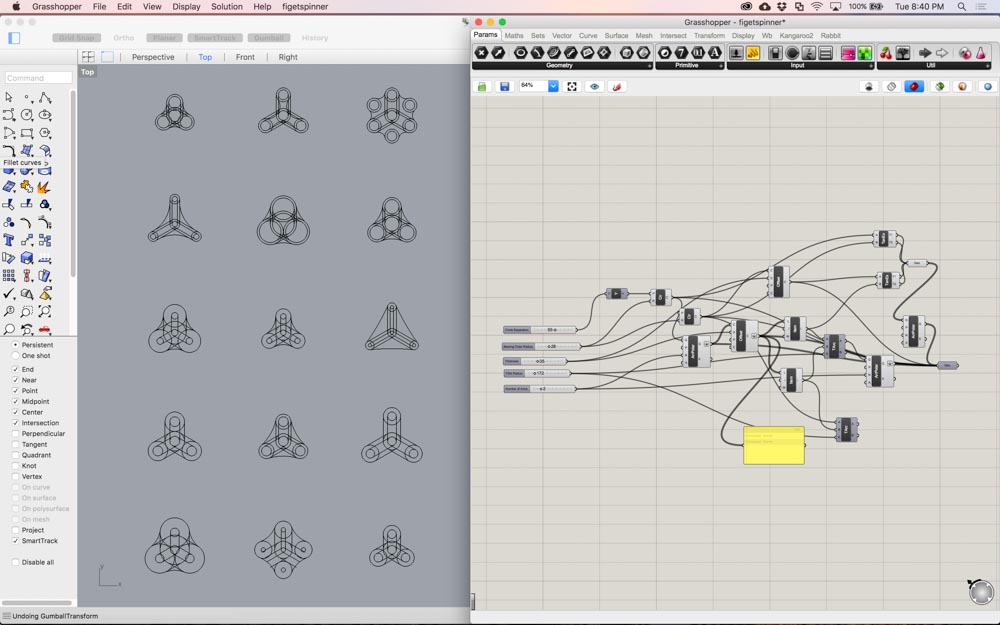
I put together a quick Grasshopper script that generates parametric fidget spinners based on a few constraints. Some of the variable parameters include the number of arms, bearing hole size, hole position or fillet radius.
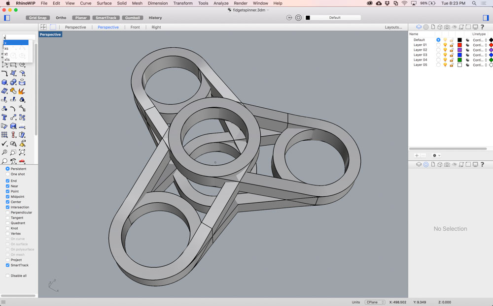
The constraints I ended up using were 3 arms, the distance between my pinched thumb and index finger to my palm (5 cm), and the dimensions of the 608-RS bearings (22mm diameter and 7mm height) that I was planning to snap on.
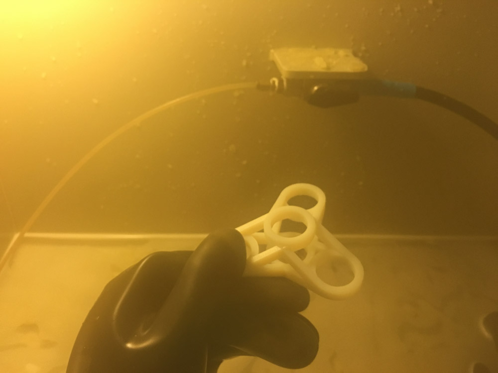
After finishing with the 3D modeling, I exported the .STL files from Rhino and sent them to the Stratasys Eden 260VS 3D printer at the CBA shop. The prints were left overnight and then I washed out the excess support material with pressurized water.
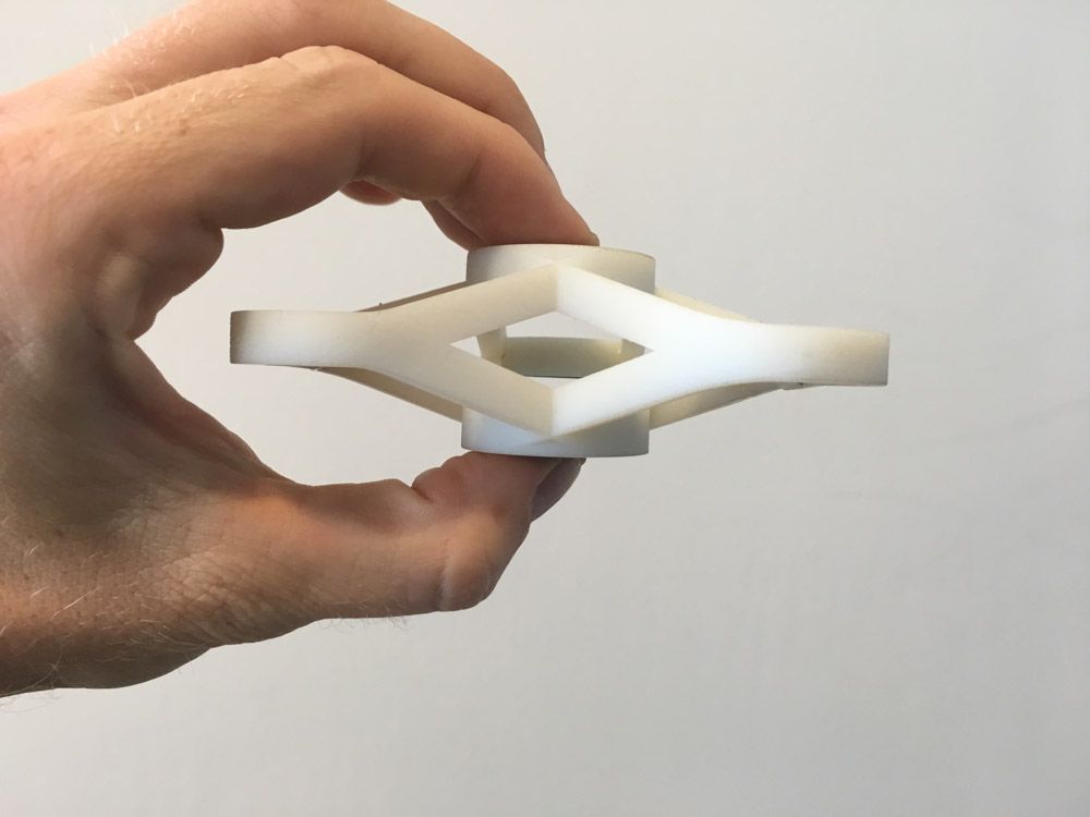
The resolution of the printer is surprisingly high, at around 16-micron layer accuracy. I was happy to see that some of the details I included in the design, such as the insertion of the diagonal braces against the rings came out nicely. The whole part was printed out of white FDM thermoplastic.
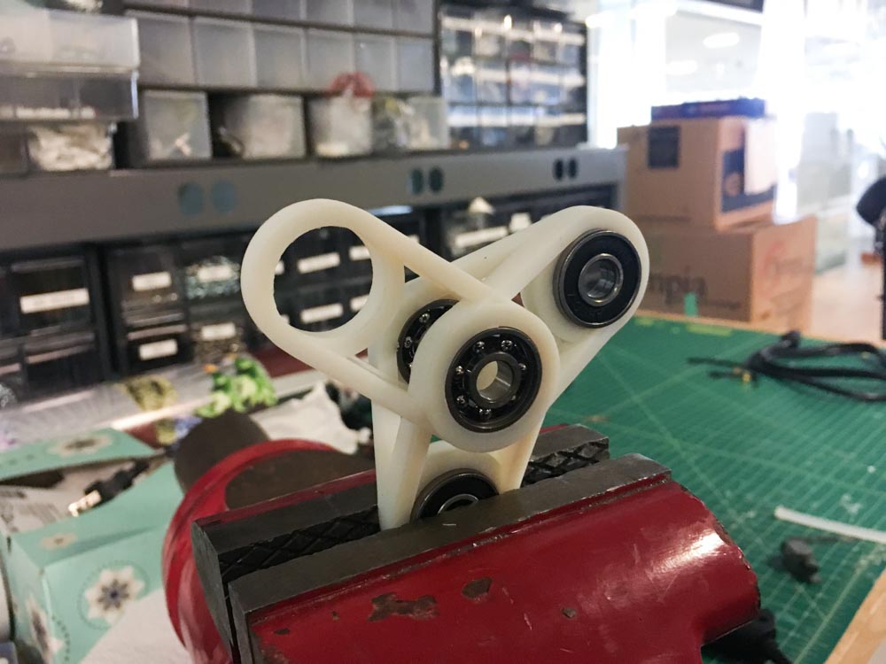
Next step was to snap on the bearings. I used a clamp to press fit the bearings in, but unfortunately, the material from the 3D printer wasn’t as flexible as I thought and the part snapped. Next time, I think I would add a tenth of a millimeter margin or carve out a conical shaped hole to make the insertion of the bearings a bit easier.
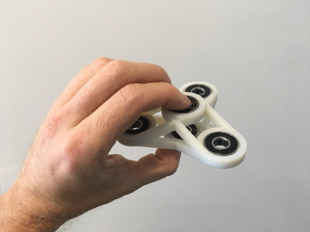
The finish of the material that comes out of the 3D printer is very close to production quality.
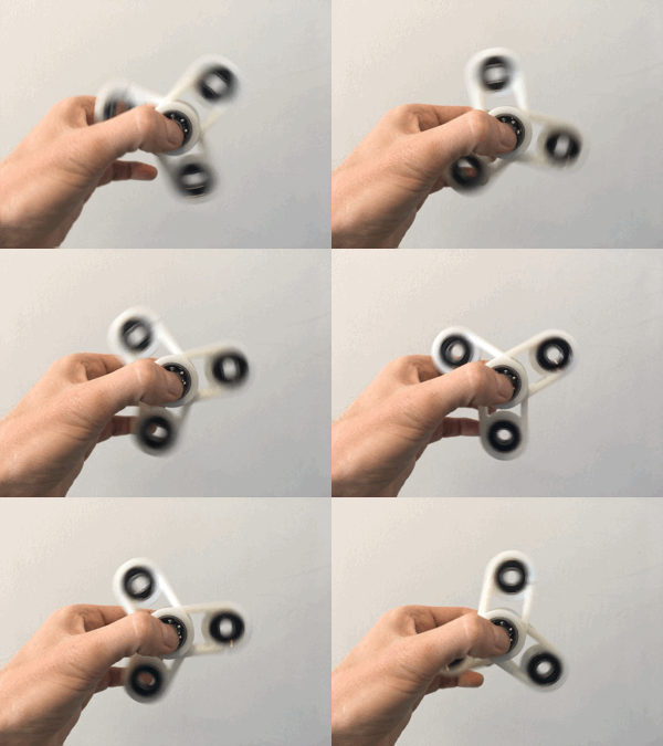
Spinning the fidget spinner again and again turned out to be really hypnotic.
Heart-in-hand
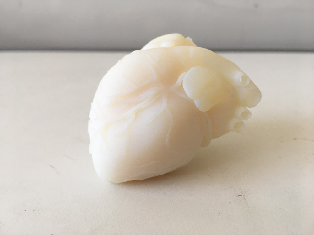
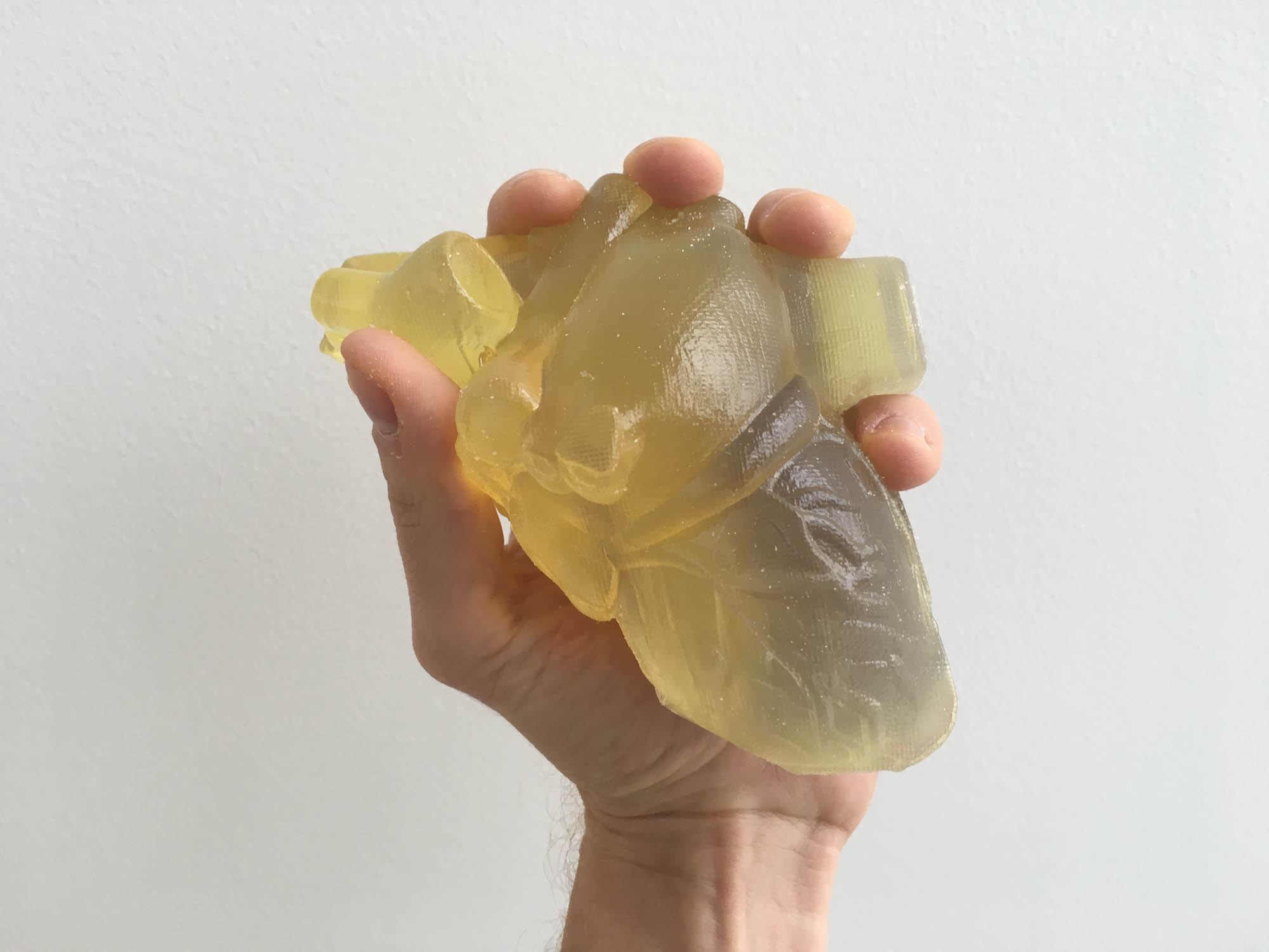
Just for (more) fun, I printed a half size human heart.


The heart-in-hand, literally.
3D scan an object (and optionally print it)
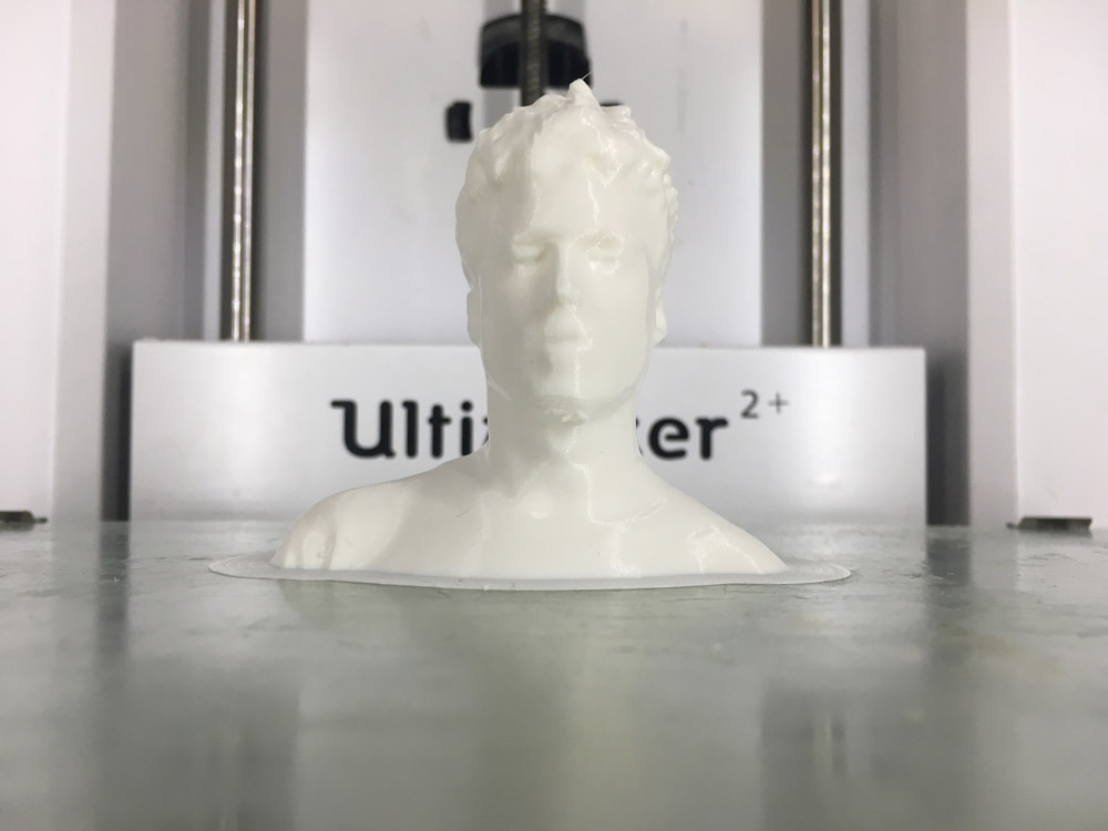
For the scanning part of the assignment, I decided to scan myself. For the final project, I’m planning on making some sort of wearable device, so I thought it might make sense to get started digitalizing myself.
Tomás helped me out with the scanning. We used a second generation Sense handheld scanner. Scanning turned out to be a bit tricky. We had to repeat the scanning a few times until the 3D model resembled something that looked like me.
We tried to do a full body scan, but the Sense stitching software had trouble picking up some of the details, especially with black colors and dark shadows. The Sense works best in areas that are well lit and with as few objects in the scene as possible, so I guess the shop is probably not the best place for scanning.
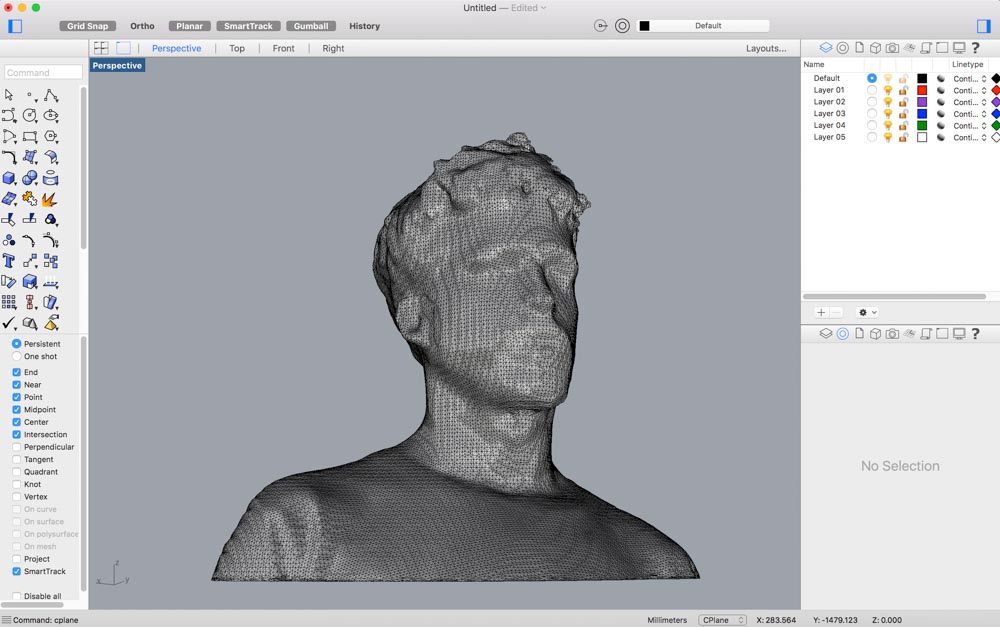
The overall shape of the mesh turned out to be in pretty decent conditions. The Sense software has a nice feature to close meshes and make them watertight, which makes it ideal for 3D printing.
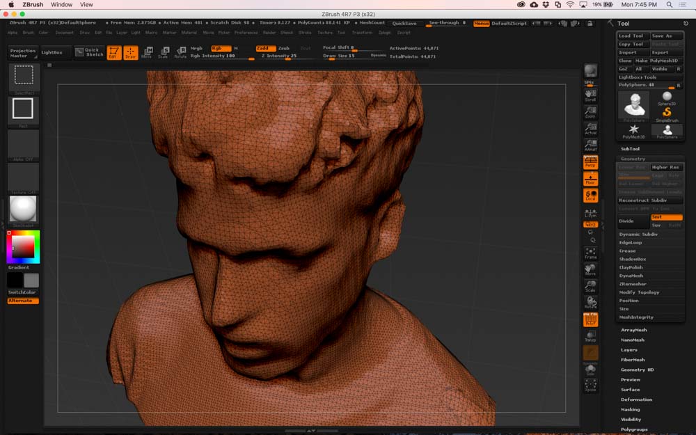
I wasn’t fully satisfied with the mesh, so I brought the model into ZBrush for some cosmetic tweaking. It’s mesh surgery time. The first step was subdividing the mesh to increase polygon count.
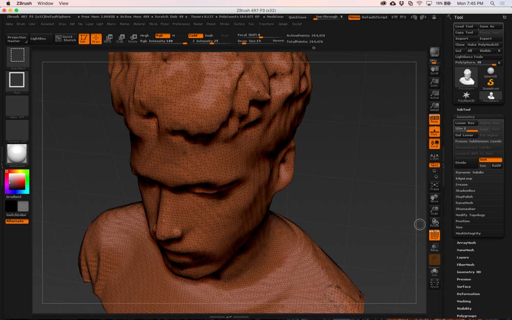
Then, I smoothed out the whole mesh. Next, I sculpted my nose, eyes, eyebrows, mouth, and ears to add more detail to the 3D model.
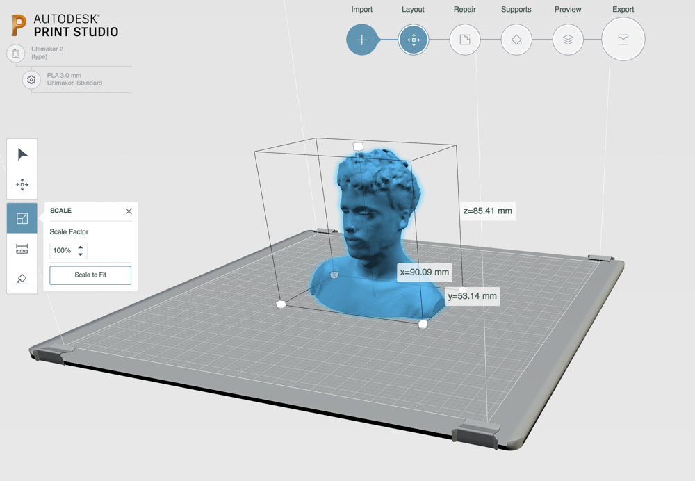
After cleaning up the mesh, I sent the file out to the Ultimaker 2+ 3D printer we have at the Fluid Interfaces lab on the 5h floor.
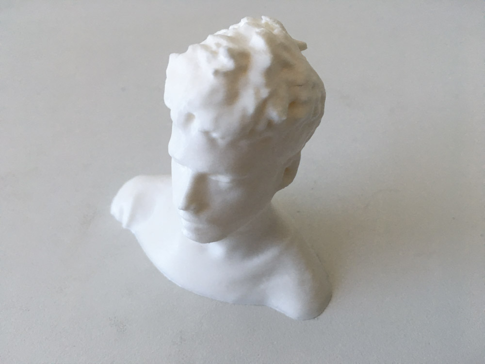
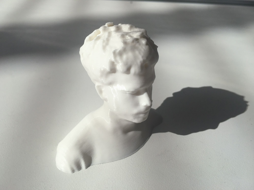
I printed the model on white PLA, using a 0.2 mm profile and 20% infill material. The model took around 6 hours to print, but now I have my own custom Oscar statue.
 \
\
Redraw the echo hello-world board, add a button and LED check the design rules, make it, and test it
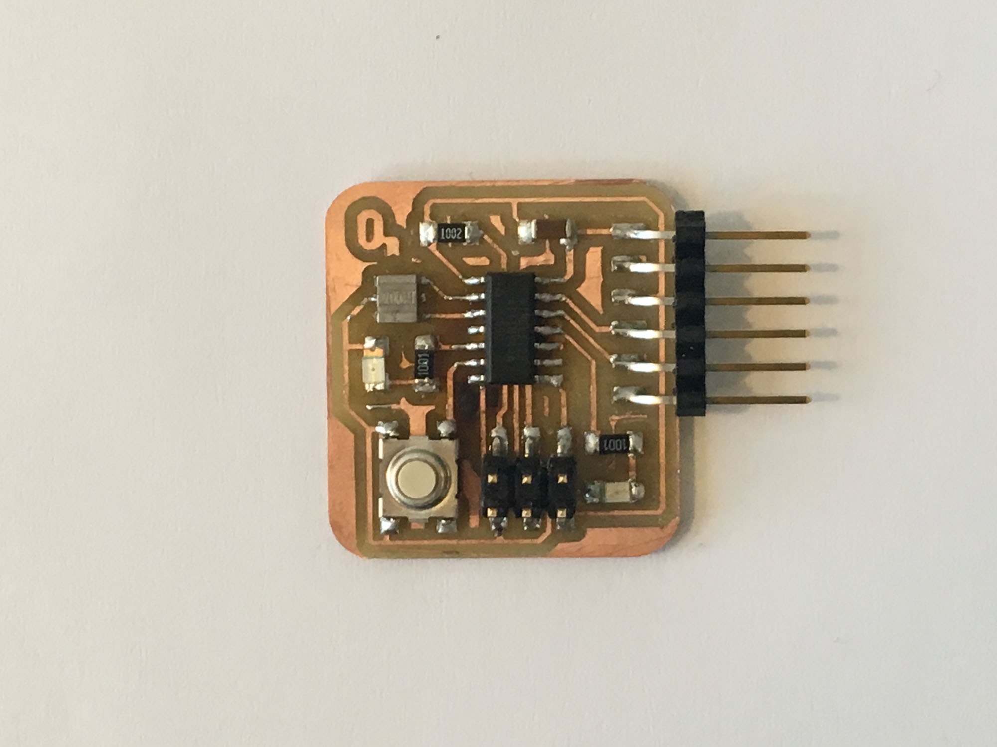
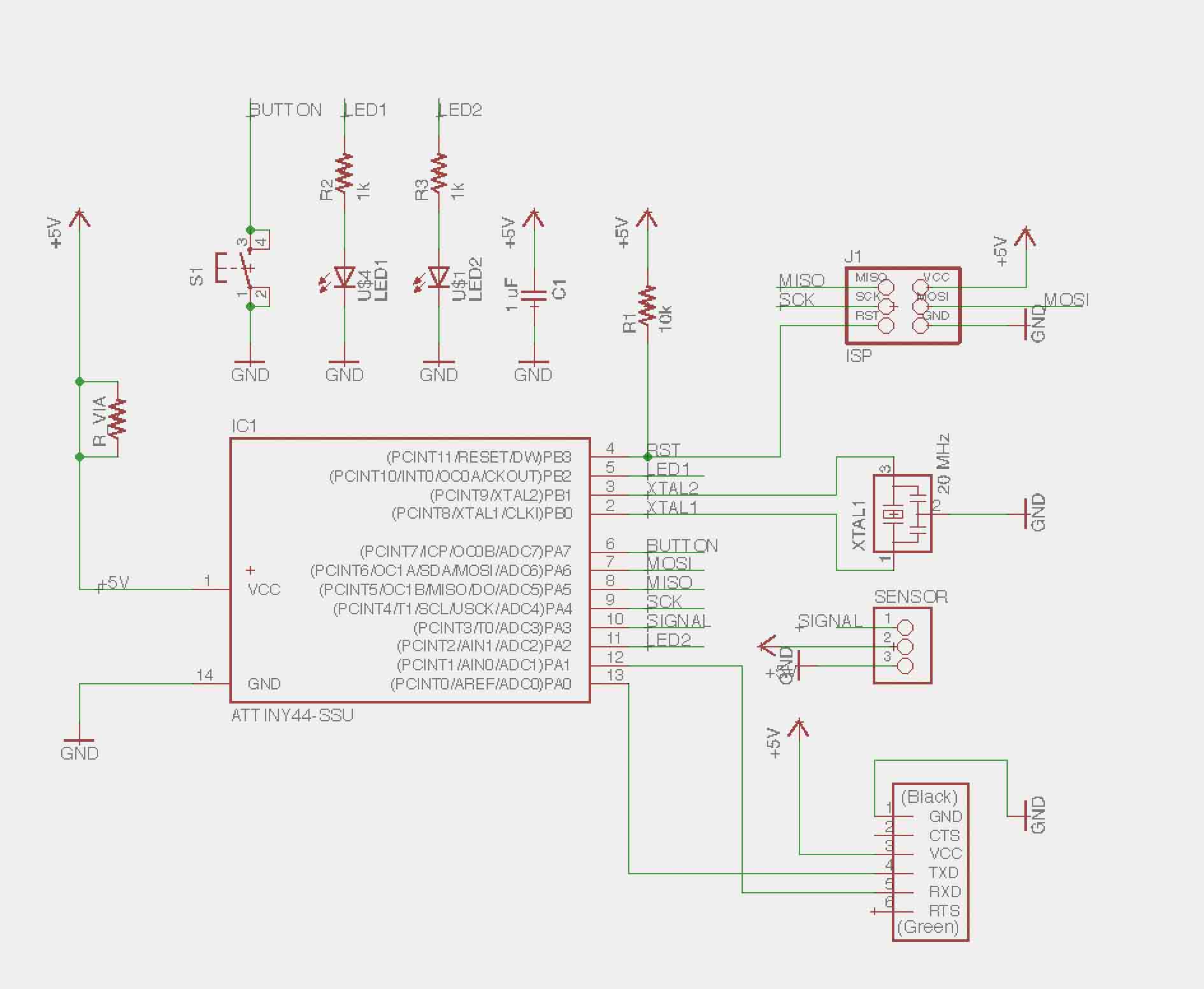
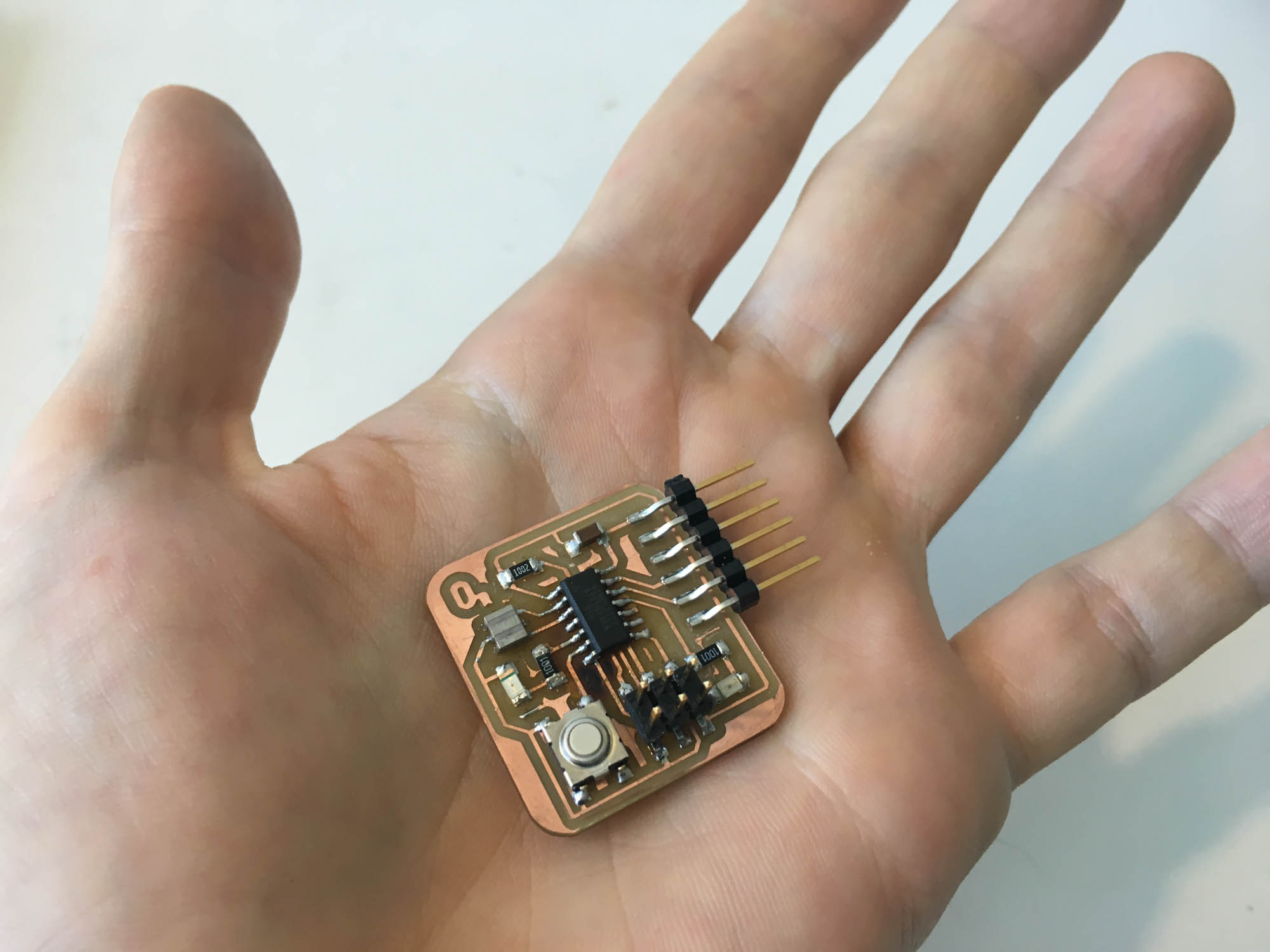
This week’s assignment is to redesign the echo hello-world board, adding a button and and LED.The overall process to follow is the following: first, interpret the existing circuit, then, draw up the schematic with the new modifications, next draw the routes for fabrication scale, then machine the board, and finally stuff the board with components and program it to make sure it works.
To draw up the schematic of the circuit and draw the traces for machining I used Eagle. But first, I had set up Eagle to include the libraries of components that are stocked in the CBA electronics workshop.
Then, I calculated the required resistance to go along with the LED. From the LED data sheet we find that the LED operates at 1.8V ≅ 2V, with a maximum current of 10mA. The input voltage form the power source is 5V, coming from the USB. V = 5V-2V = 3V. The maximum current the LED can take in is 10mA, so we will operate it at ~30% and to round up the division. I(Max) = 0.01A; I = 3E(-3)A. Next, we use Ohm’s Law to find the value of the resistance to be placed in series with the LED. From R = V/I; R = 3V / 3E(-3)A = 1kΩ.
The next step was drawing the schematic in Eagle. I placed the parts that are part of the echo hello-world plus two additional LED’s and a switch.
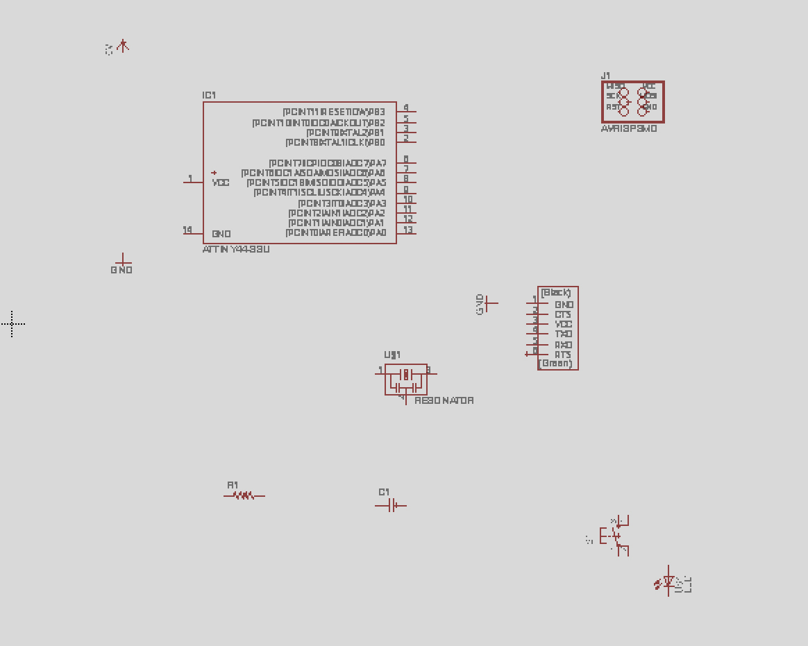
Then, I started netting up the parts with the ‘net’ tool. I used ‘name’ to change the name of the components to match the board layout. I also used ‘value’ to make sure the values of the components match the ones in the original design.
To avoid overlapping nets, there is a design pattern that can be used to draw invisible nets: first, start drawing a net from a pin, then, use the ‘name’ command to rename it. Then, use the ‘label’ command to display the name. Then, repeat the operation for the other wire you want to connect it to. Eagle will prompt the user and suggest connecting the wires. This will create an invisible connection that can be revealed with the ‘view command’.
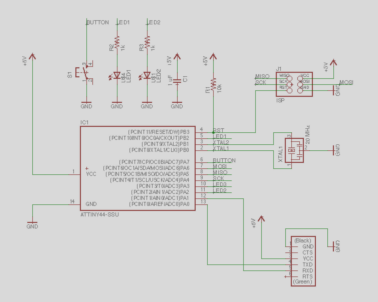
After all the connections are in place, I ran the ‘erc’ command to make sure everything is correctly connected. I also ran the ‘show’ command to make sure all the hidden wires are connected to the right position.
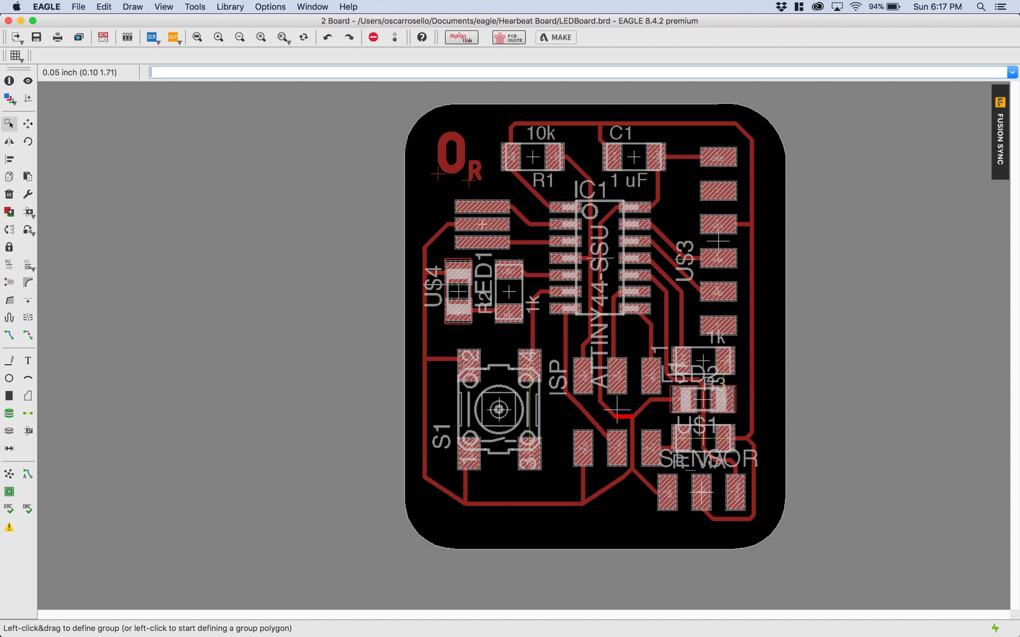
Once the schematic is done, the next step is moving to drawing the board traces. To switch between the schematic and board modes in Eagle, use ‘edit .brd’ or ‘edit .sch’ between them.
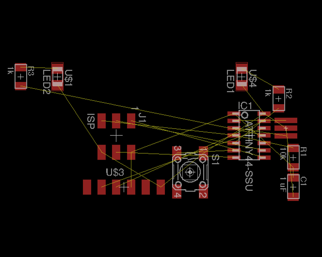
The first step is laying out a rough position of the components to minimize intersections between prospective routes.
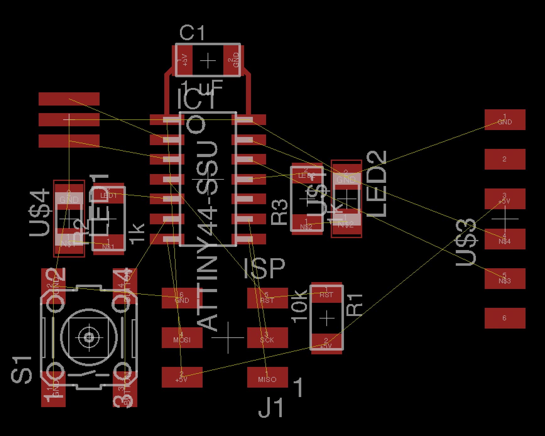
To organize the components, I used the ‘move’ command. To rotate the components in place, click with the right mouse button while you are moving the component. When routing, holding ‘alt’ refines the position of the routes. Some useful shortcuts:
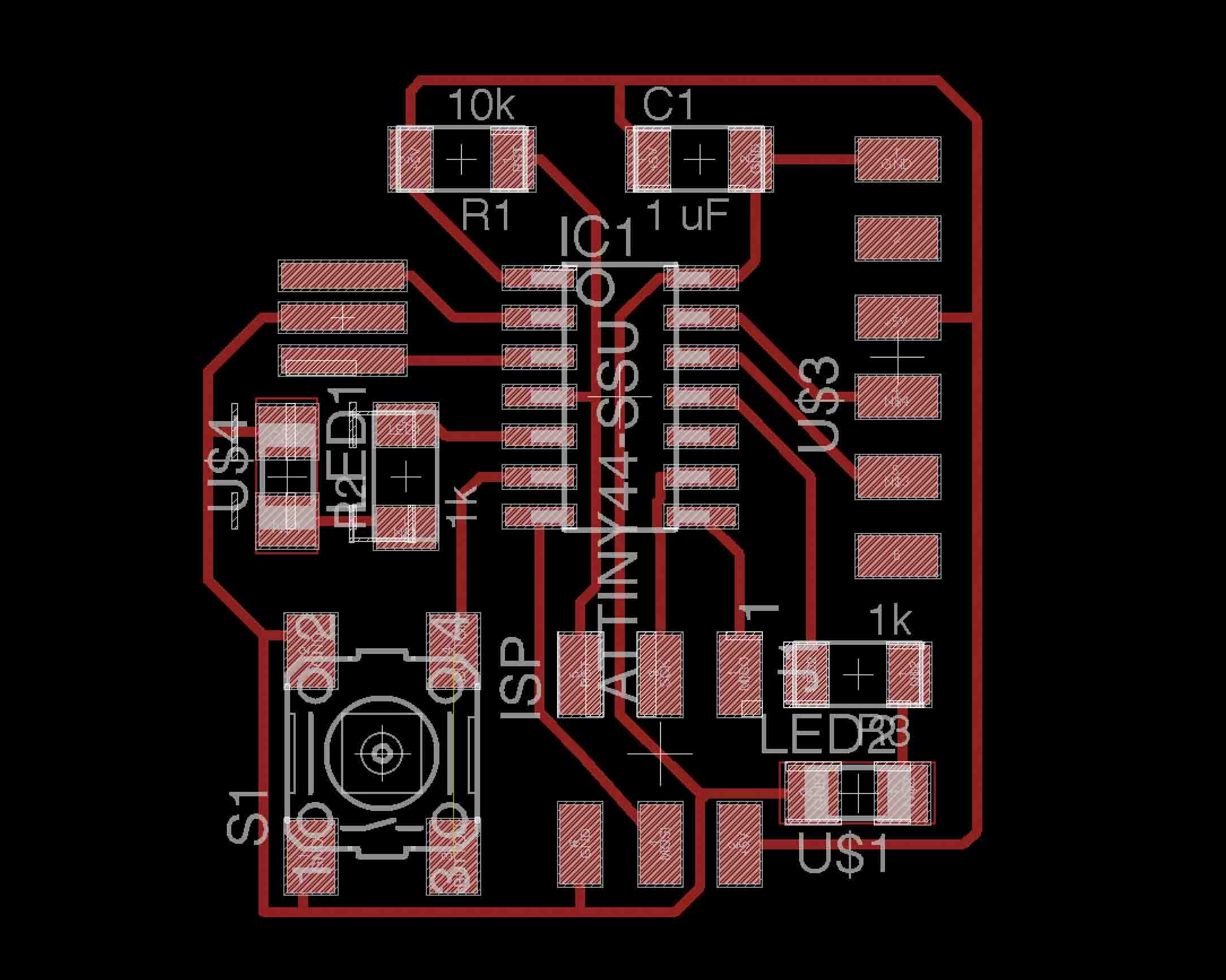
Next step was exporting the .png files for fabrication. I made sure the ‘monochrome’ setting is enabled and output resolution is 1000 dpi. Then, I exported two files, one for the traces and another one for the board outline. Some more useful shortcuts to display the correct layers:
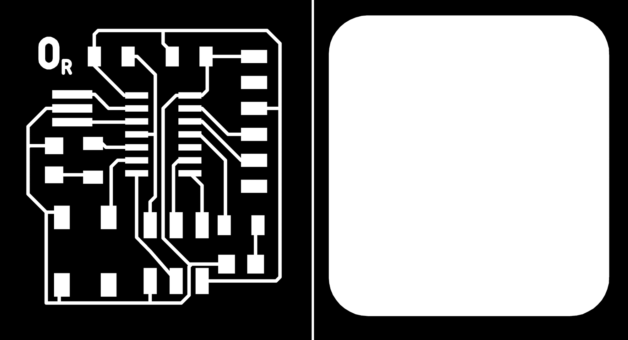
After exporting the .png files, some extra processing needs to be done to ensure a smooth milling process. I added 110% extra pixels in Photoshop around both files to leave some room for fabrication. For some mysterious reason, Eagle scales the output .png’s at double size, so I had to go back to Gimp and scale the blueprints by 50%. Off to the Modela MX-20 milling machine!
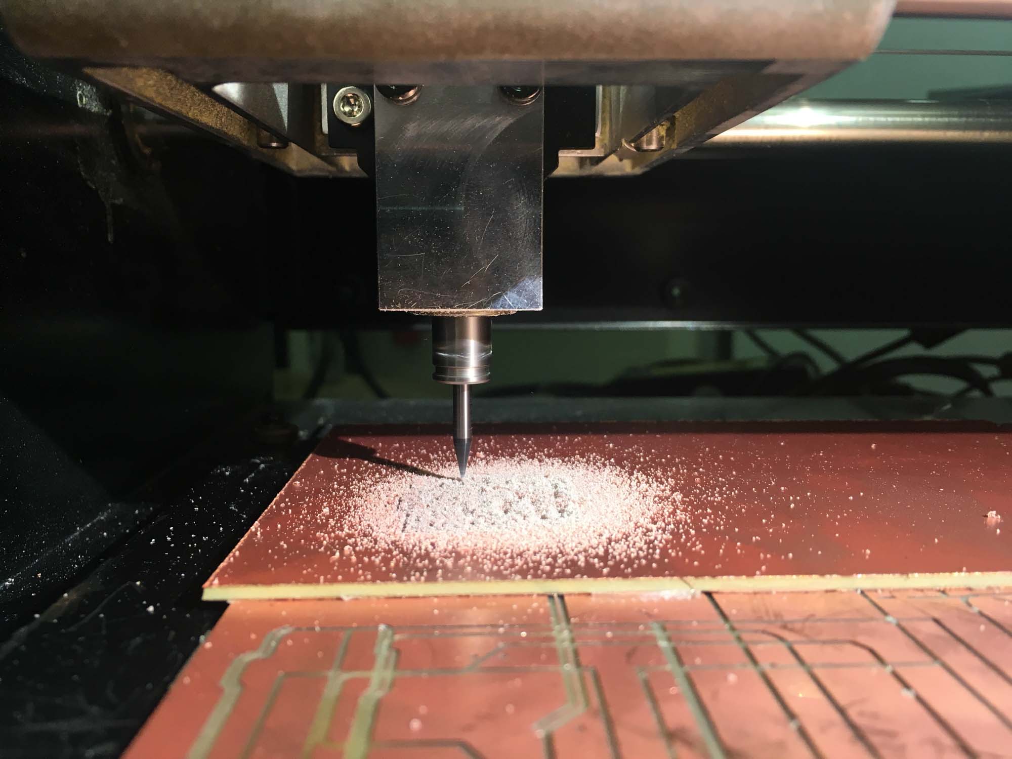
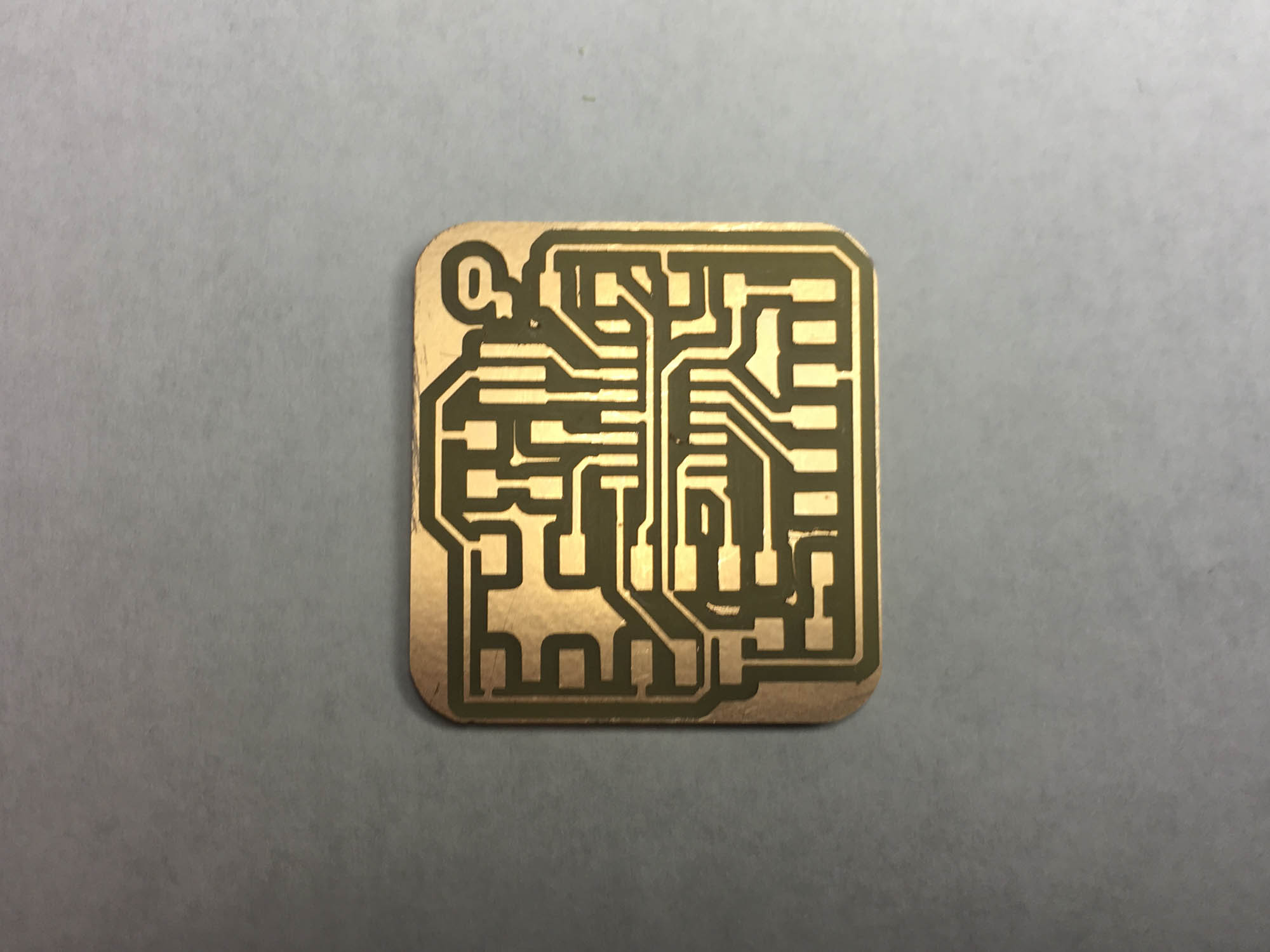
Unfortunately, I forgot to scale the outline and the 1/32 end mill went right over my traces, so I had to mill the board again.
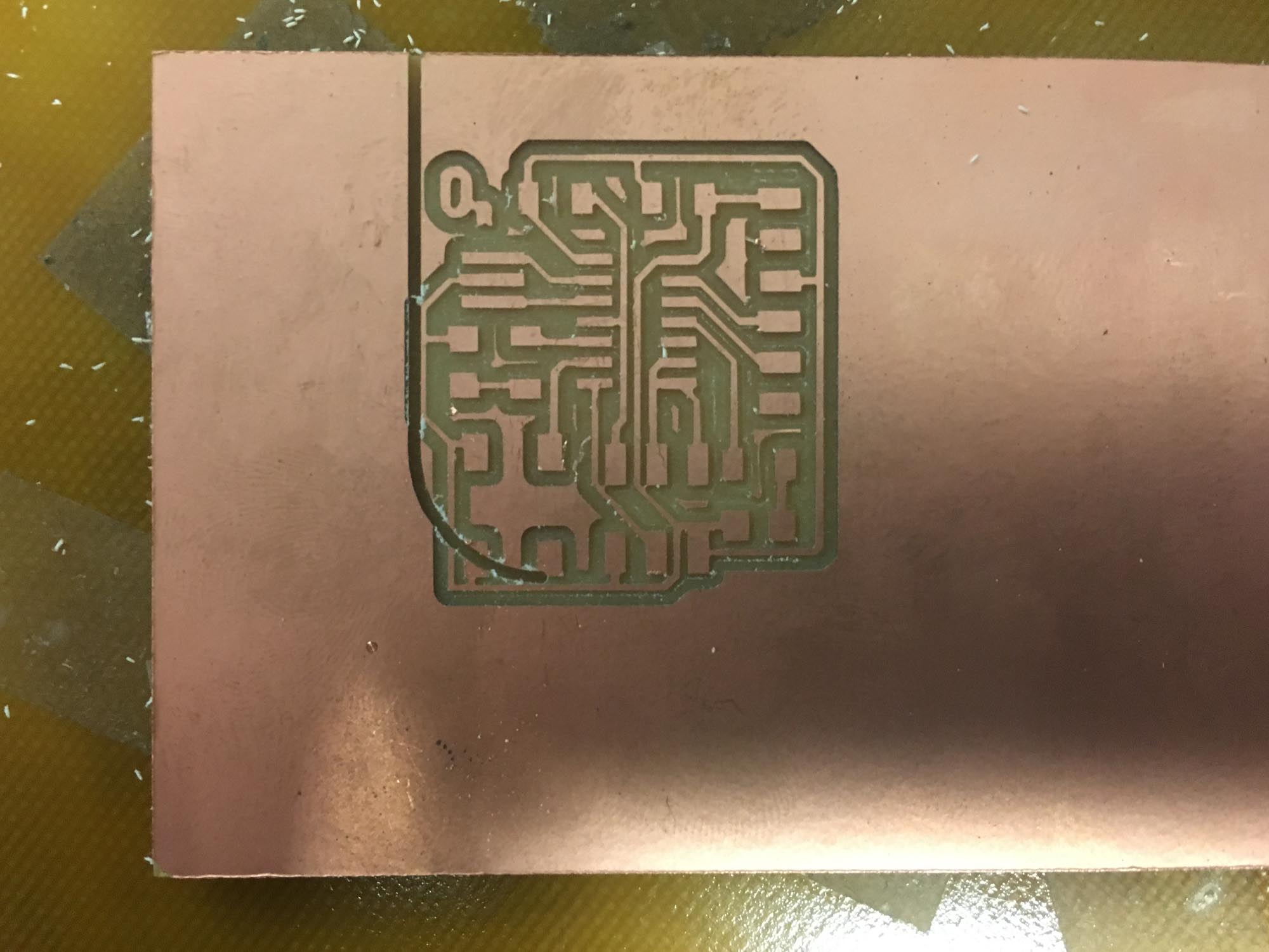
I ran the file again, this time at the correct scale.
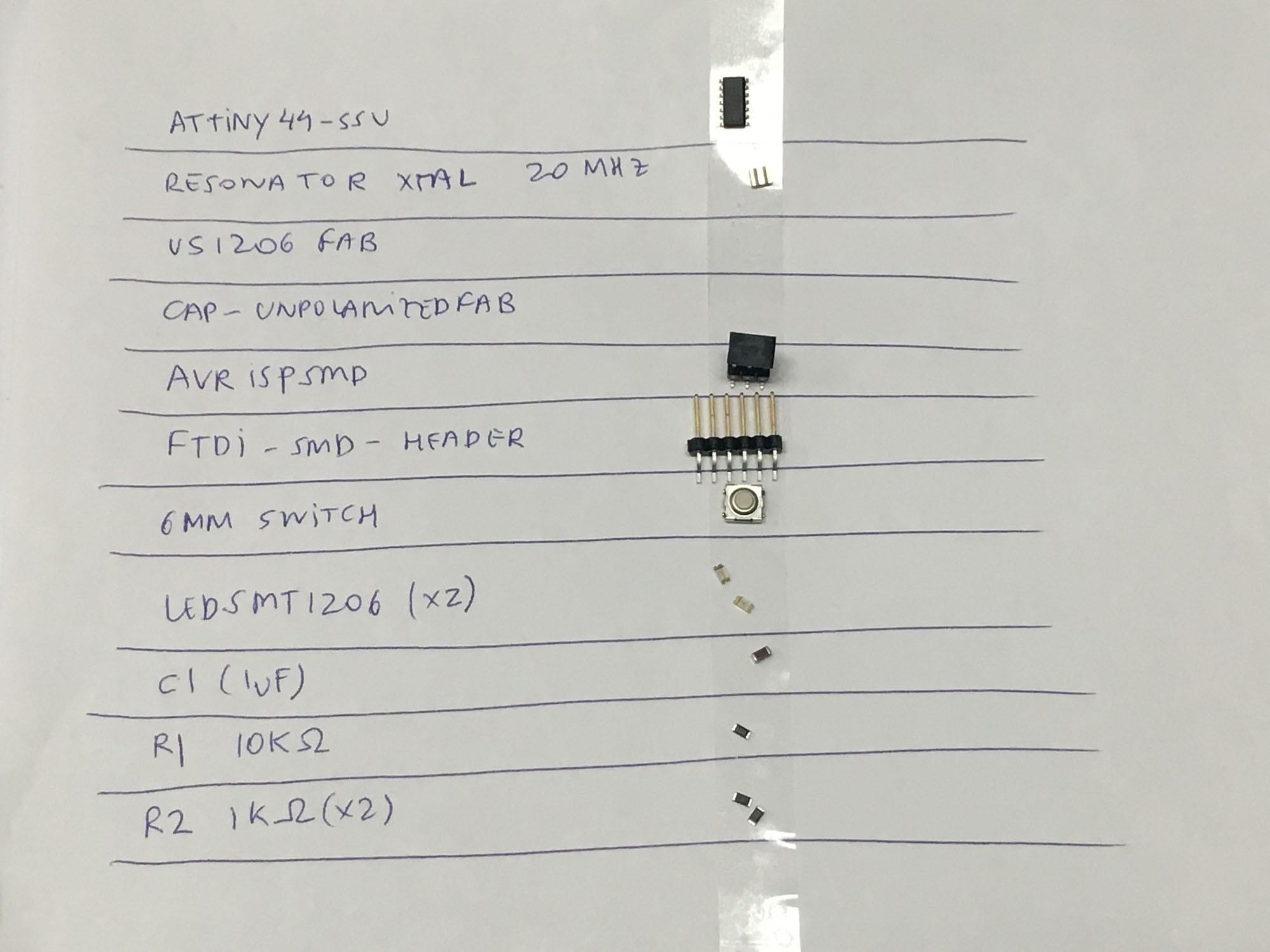
Next, I picked the components. To avoid the component mixup that happened in Week 3, I laid out the components in advance.
Stuffing the board didn’t completely go as planned. I made sure the orientation of the components was matching the specs, including making sure the green stripe on the LED was touching the ground.
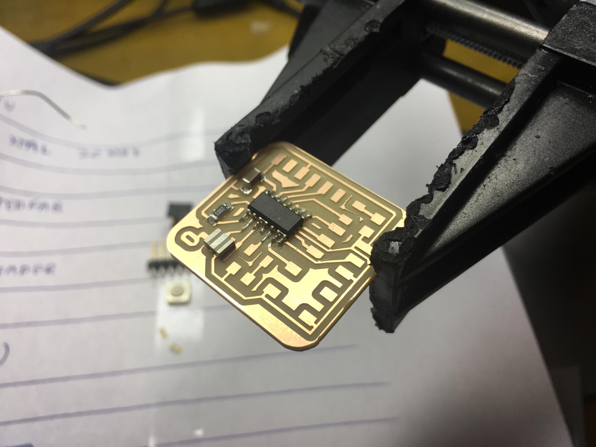
After soldering the ATTiny44, I checked for continuity with the multimeter and, oh no, I found there was continuity between two adjacent pins. So, I took the ATTiny out, with the help of the heat gun. The problem turned out to be from the traces and not the soldering job. Some of them were too close together and shorting the circuit. So, I had to cut off a chunk from two pads in order to avoid a trace running into it.
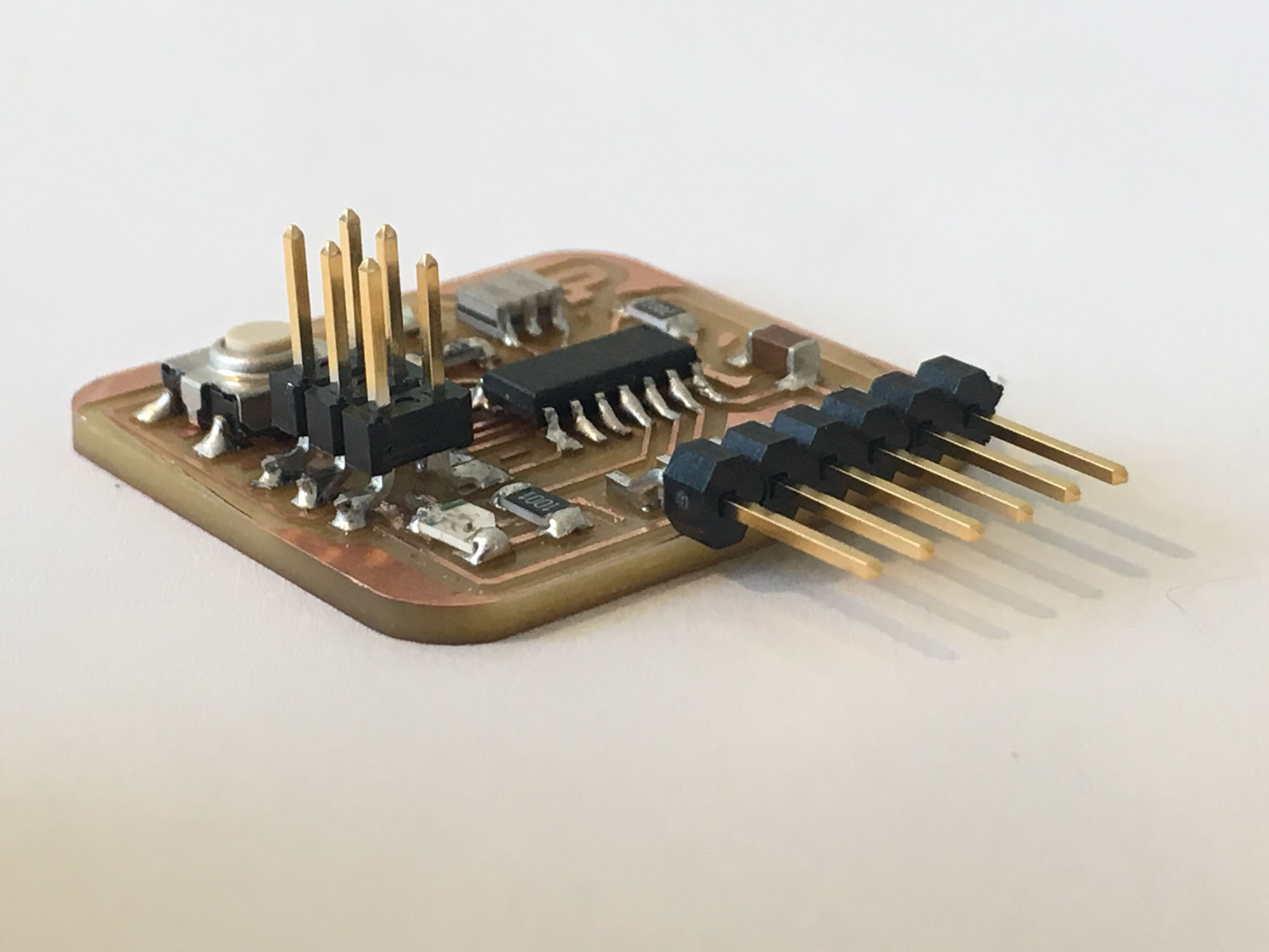
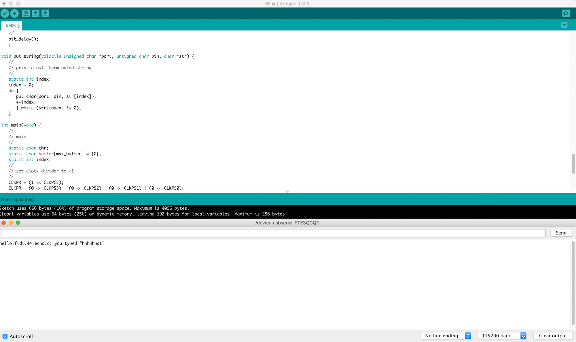
To test the board I loaded Neil’s echo program using the ISP programmer we built in Week 3 to program the new board. Naturally, it crashed.
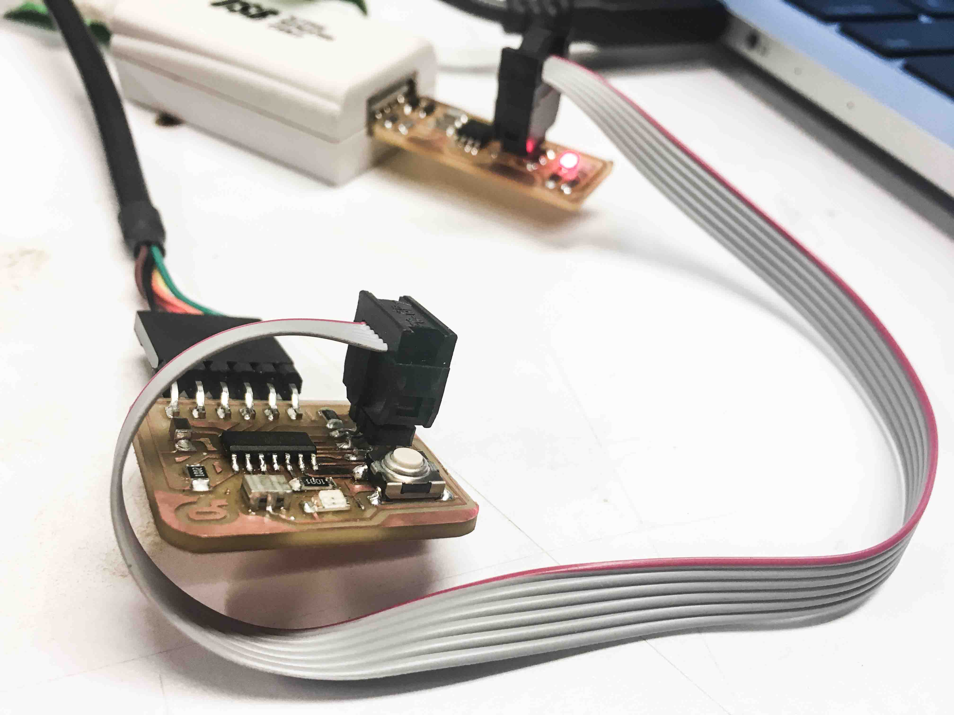
But after fixing the settings in the Arduino IDE and installing the board settings from here, the echo program ran smoothly. Horray! I used the following settings for the Arduino IDE:
Big thanks to Tomás aka ‘technojesus’ this week for helping out figuring out Eagle nuisances and major hardware debugging of my board. Also, thanks to Thras for setting up the right options in the Arduino IDE.
Make something big
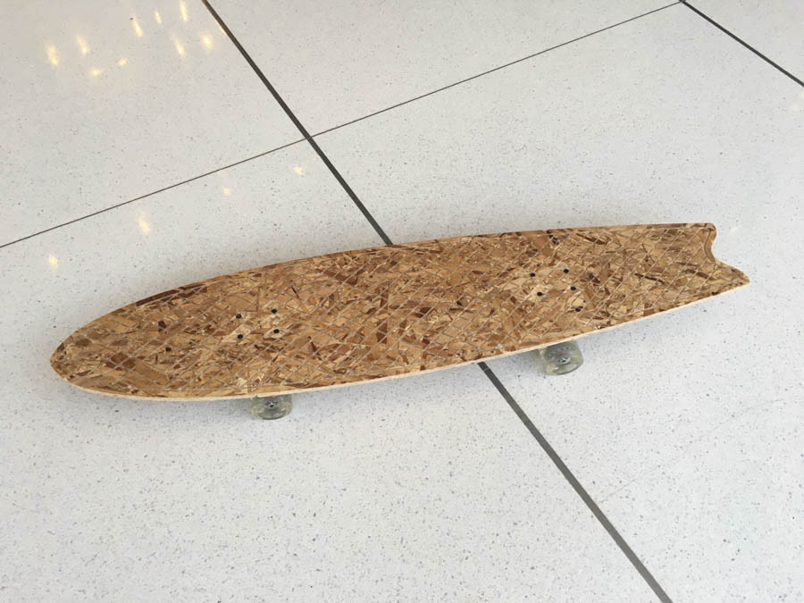
This week we are making something big. Scale is relative to size, so I picked something big compared to what we did the previous week. I was also interested in making something I could have fun with so, this week I’m making a really big longboard.
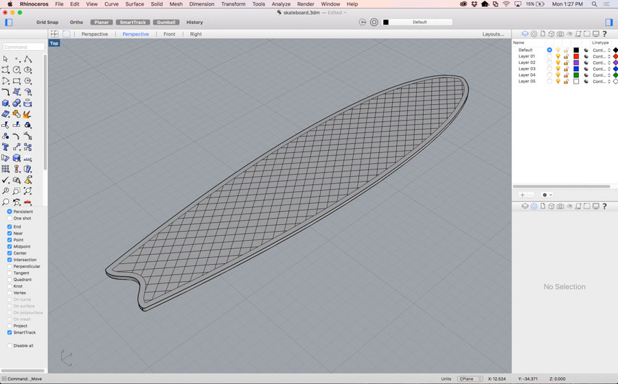
The design was modeled in Rhino. The profile was free sketched to somehow match the shape of a fishtail surfboard. The only fixed size was the 180 mm maximum width, coming from the width of the trucks I had available. I also added a grid pattern to increase the grip of the surface. Then I drew 5 variations of that design to try to make the longest longboard in oriented strand board (OSB). OSB is not the best type of wood to make skateboards out of, but I was interested in seeing how big of a longboard I could build given the material.
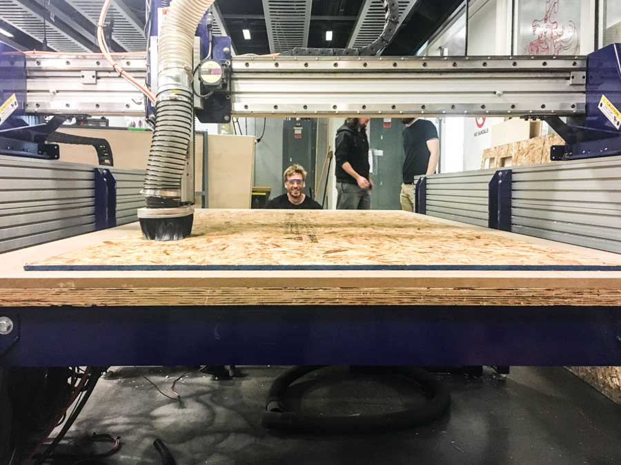
The first step is loading the material onto the bed of the machine. The material goes on top of another wooden fiberboard medium density sacrificial layer, that gets damaged in order to be able to cut through the material. It’s important to make sure the material lays flat on the board and is parallel to the edges of the machine, to make the most use out of it. Then, we drill screws onto the edges to support it.
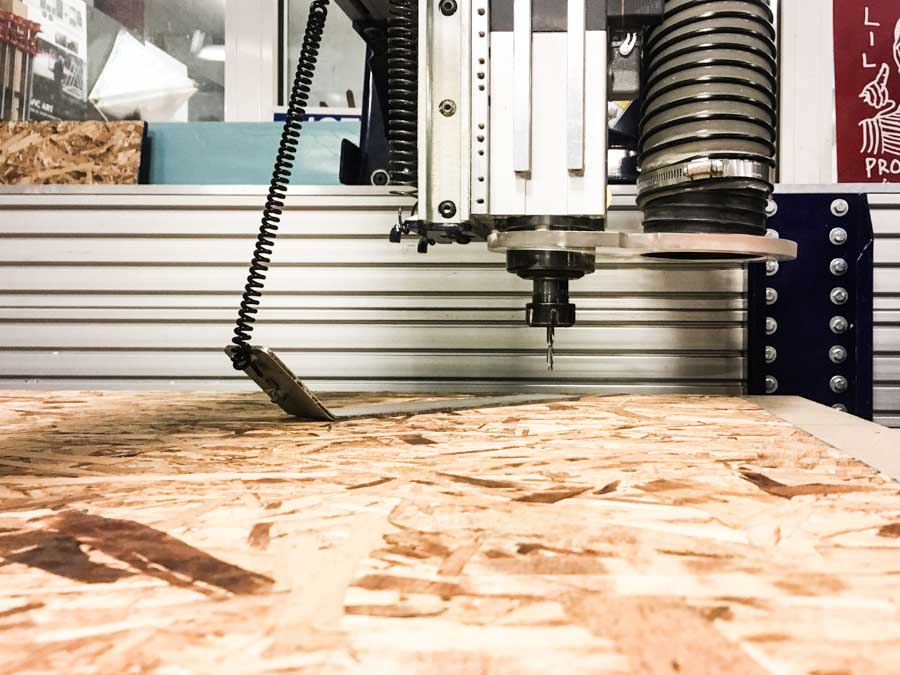
Then, we load the tool with the appropriate collet size. For this job, I used 1/8 in flat end mill. To load the end mill, we used the two wrenches to tighten it. Next, we move the end mill to the bottom righthand corner to the material and set the XY origin. After, we zero the Z axis using the metal plate attached to the machine. This process is automated, and when then mill meets the metal in calculates the 0.0Z point for the material.
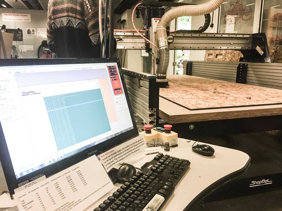
The next step is opening the cad file in VCarve Pro. The software is not at all intuitive to use and it’s important to get all the parameters right in order to minimize surprises during the cutting process.
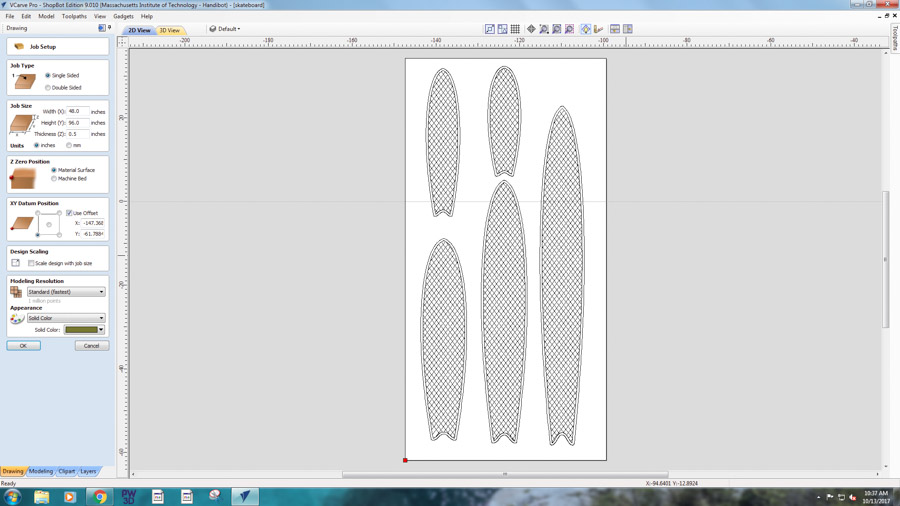
In VCarve, we need to set up the material size to match the board size. The origin also needs to be reset to the bottom left-hand corner. The next step is opening the cad file in VCarve Pro. The software is not at all intuitive to use and it’s important to get all the parameters right in order to minimize surprises during the cutting process. In VCarve, we need to set up the material size to match the board size. The origin also needs to be reset to the bottom left-hand corner.
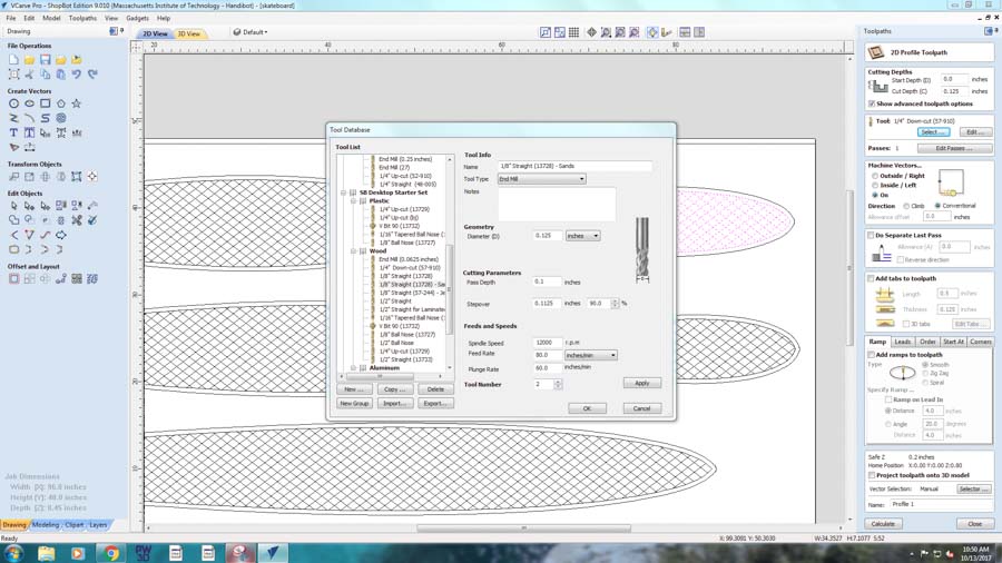
Then, we generate the tool paths from the cad files. First, we select the lines we want to create tool paths for and then calculate a path that matches the tool properties we are using. The pass cut depth shouldn’t exceed the diameter of the tools, so in order to cut all the way through the 0.44 in OSB board, the software will automatically do it in multiple passes. In my case, I had two types of tool paths, one for the outer cut and another one for the grip pattern score.
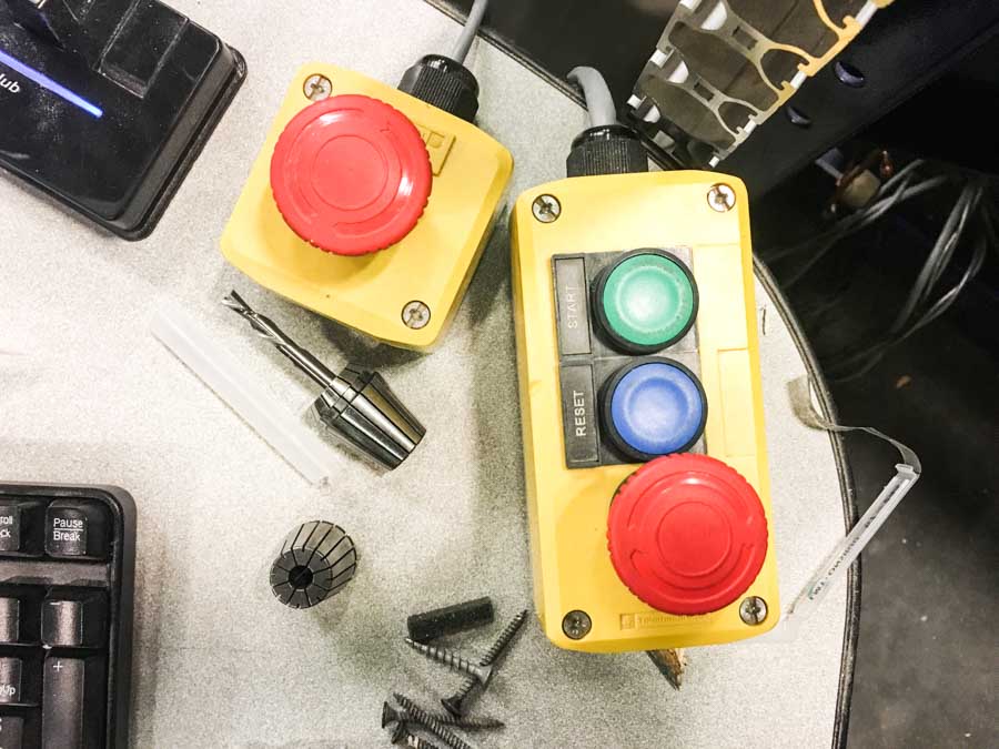
Moment of truth, time to press the green button and keep a hand on the big red button in case the mill decides to drill where it shouldn’t.
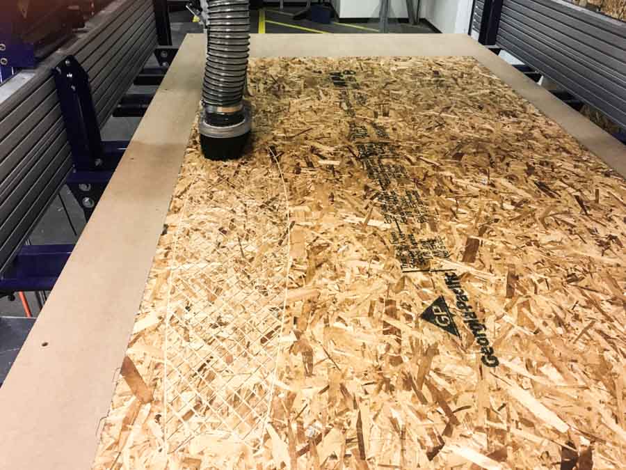
After the lengthy setup, the milling process was going pretty smooth. All the scored grid pattern was in place, but then, the machine stopped. The end mill snapped.
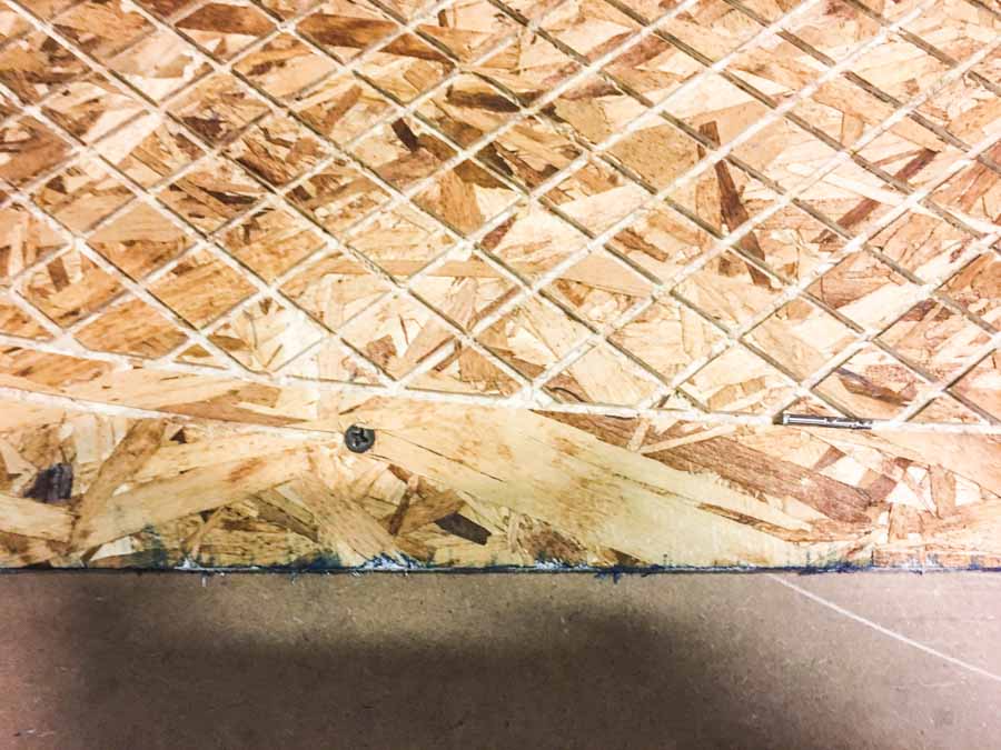
On closer inspection, I found that the cut path went right over one of the screws supporting the OSB board. Lesson learned: leave enough room at the edges, not only to account the discrepancies between the board position and the zeroing, but also to include enough room for the supporting screws.
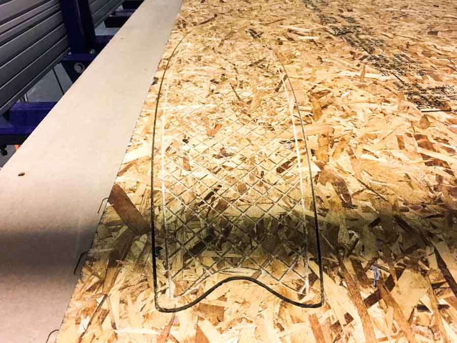
I unscrewed the screw, replaced the tool, zeroed the new end mill and then cut again on the same path. This time without major trouble. However, I decided to cut out only one board, the process took much longer than anticipated and after seeing how the first board came out, I don't think OSB would be able to handle larger boards than the one I had just cut.
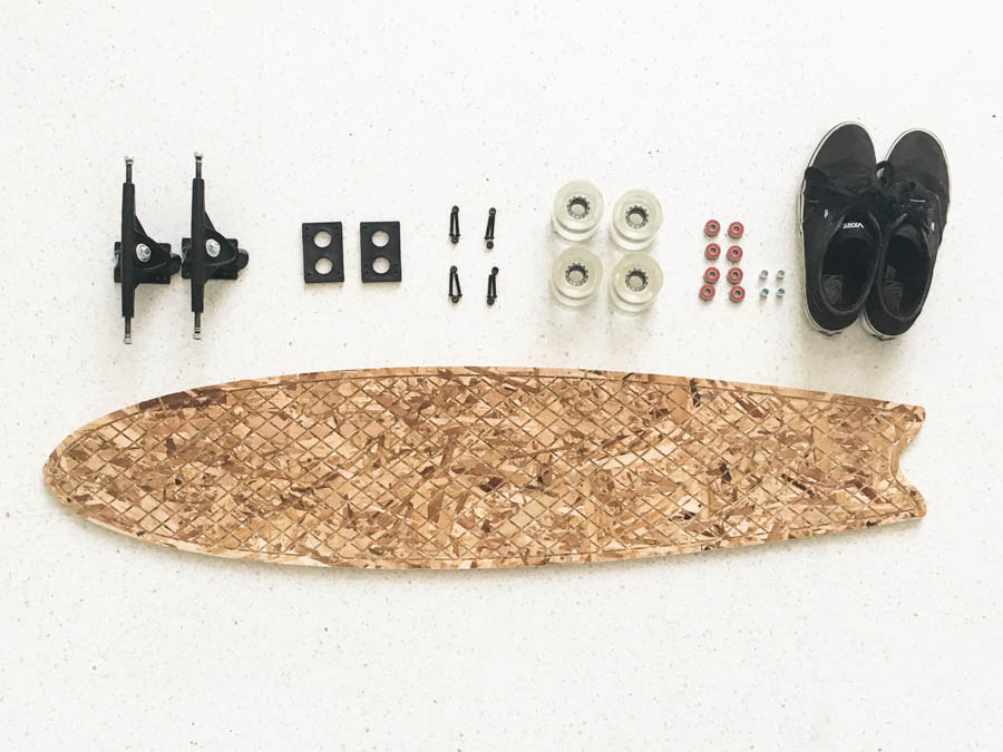
After the board was cut, it’s assembly time. Tomas gave me a hand with the assembly of the trucks and riser pads, and snapping on the bearings onto the wheels was quick. I had to put the trucks closer together than I was anticipating as OSB is very flexible, but snaps easily. So for safety, I tried a couple of different truck configurations and in the end settled for a conservative choice.
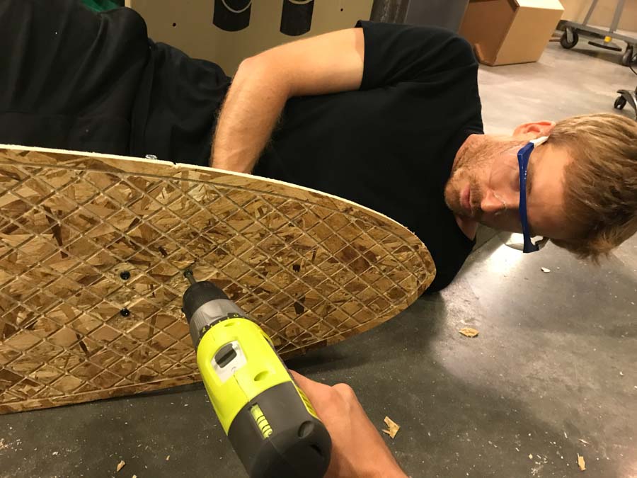
Then we drilled on the trucks. Some of the diamonds from the grip pattern broke when drilling the screws, but then looking back it makes a nice pattern of having some of the diamonds missing. We also had to include washers to account for the irregularity of the OSB surface.
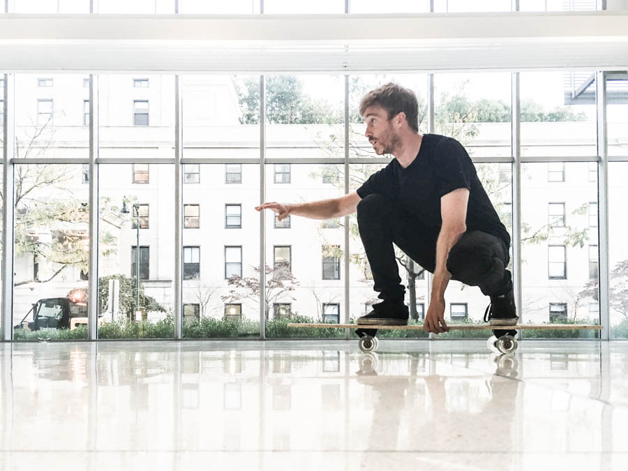
Time to ride. With some caution, I stepped on the board but it turned out to be much more sturdy than I anticipated. I was careful to just step on top of the truck screws, just in case.
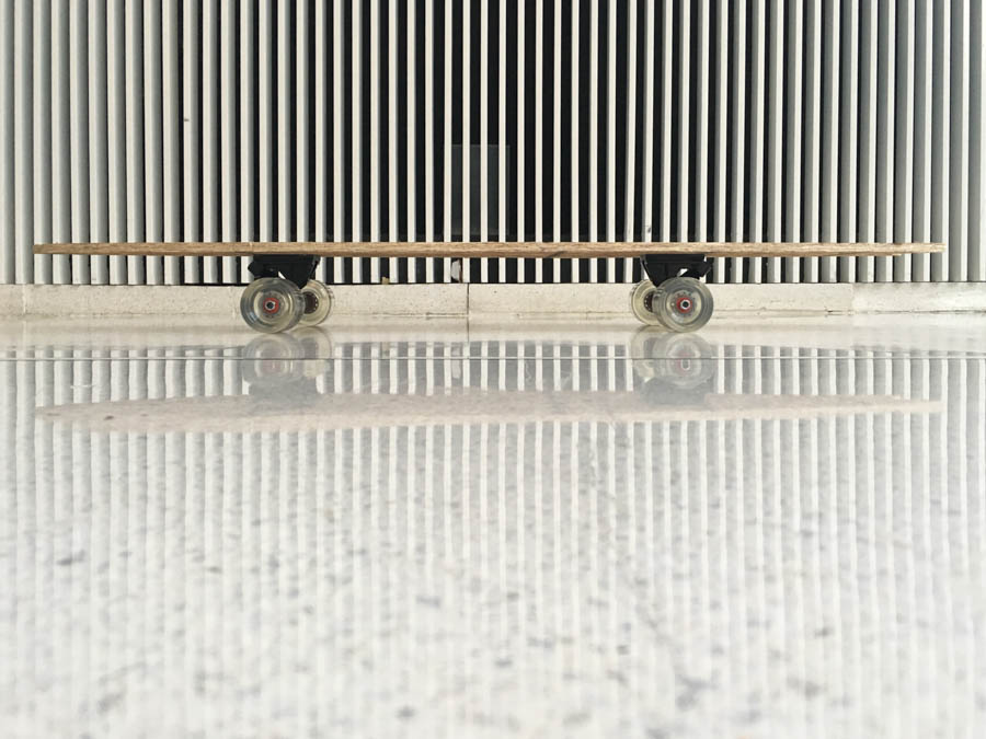
Next, I took some pretty pictures of the product before starting to abuse it.
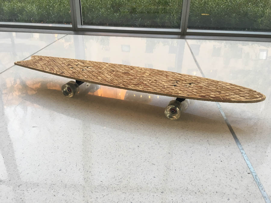
And after, it was play time.
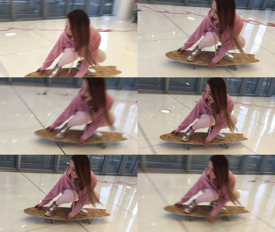
Xin turned out to be a natural on it. Tomás contributed to some nice sliding action and also to snapping the board in three pieces.
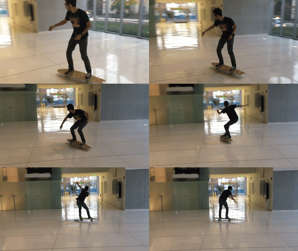
Version 2.0 will keep the 17-inch wheelbase and with, but it will be a bit shorter and definitely less cantilever on the nose and tail. I will also consider using a 7 or 8 layer maple plywood next time. As a bonus, check out how professional boards are made here.
Read a microcontroller data sheet and program your board to do something
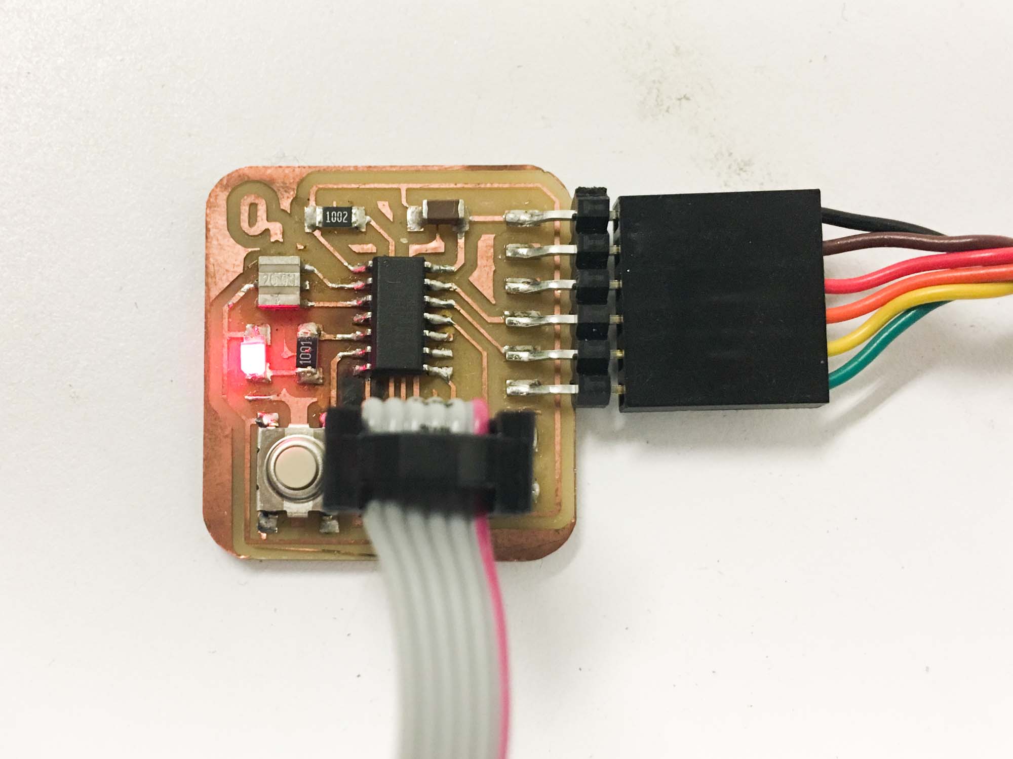
The goal for this week is to take the board we designed and fabricated in week 5 and program it to do something. My board had a button and 2 LED’s so I’m planning on testing a few configurations given the hardware.
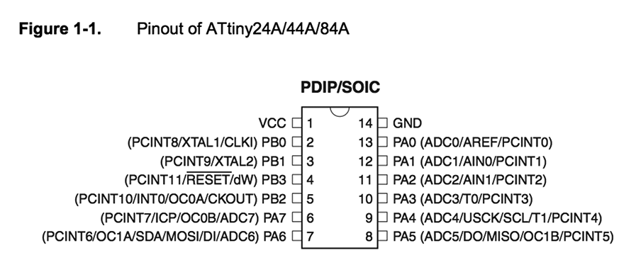
The first step was going through a couple tutorials on AVRs. I found a good tutorial referenced on Eytan's website. After that I found an excellent source on Hackday that covers an introduction to embedded programming on AVRs. From that I took away that to light up an LED just wire up the circuit to a pin, make that pin an output, and set it to a logic high (5 volts). Then, to add a button, I will need to connect it to a pin that is set as an input and program the chip to measure the voltage level of that pin.
Reading the Atmel ATtiny44A data sheet was definitely not fun. But, going through the 286 pages helped me understand a bit better about the architecture and what each pin was doing. The ATTiny44A is roughly a low-cost computer in less that 0.5 mm2.
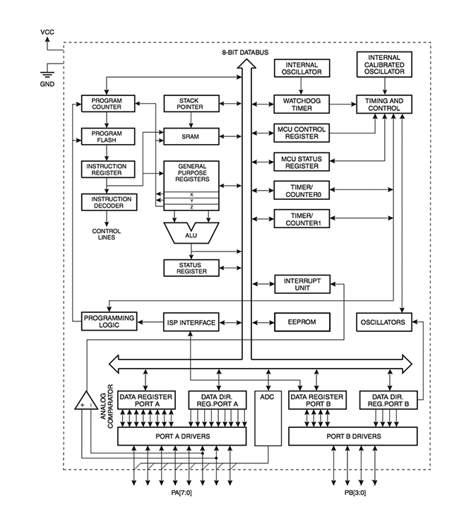
The ATtiny44A is part of the AVR family and are modified Harvard architecture 8-bit RISC single-chip microcontrollers. They are also used in the Arduino boards.
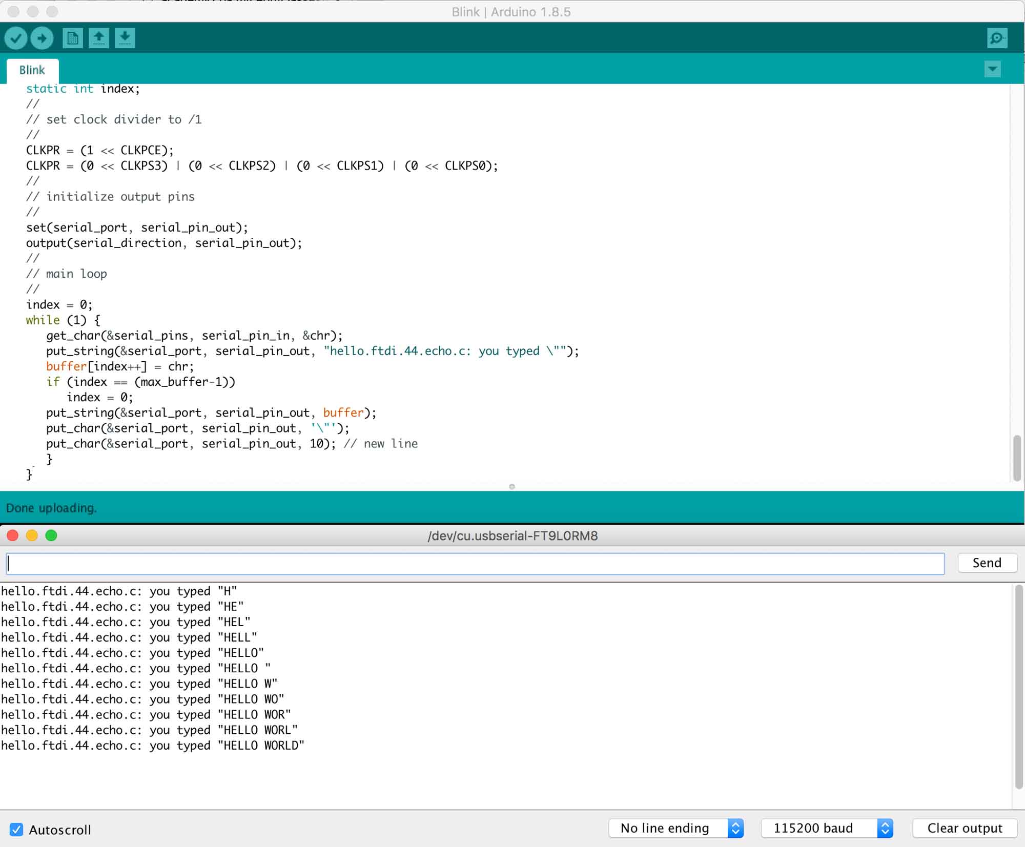
The next step was using the hardware programmer to program the board I designed in week 5. I started by loading Neil’s echo program. To do that I set up the Arduino IDE to talk to the programmer that will program my board via the 6-pin ISP header. I had to set the board to ATTiny44, the clock 20MhZ, to match the resonator, select the proper USB serial communication port, burn the bootloader and then open the serial monitor @ 115200 baud. The program worked as expected, and through the USB serial, I was able to talk to the microcontroller.
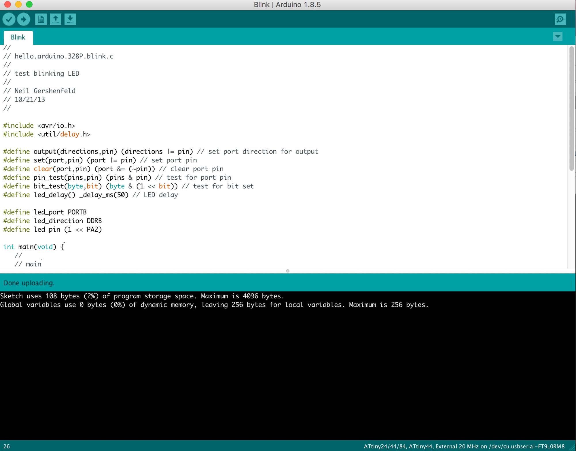
The next test was trying the LEDs on my board. For that, I used Neil’s blinking LED code. The program worked as expected and lit up the LED2 on my circuit. That was a really exciting moment, as I thought that something might have gone wrong during the PCB fabrication.
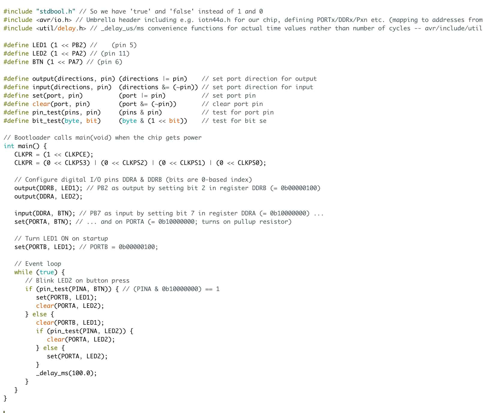
After that, I worked on getting the 2 LEDs on my board to work with the switch. For that, I started with Raphael Schaad’s code and adapted it to my design.
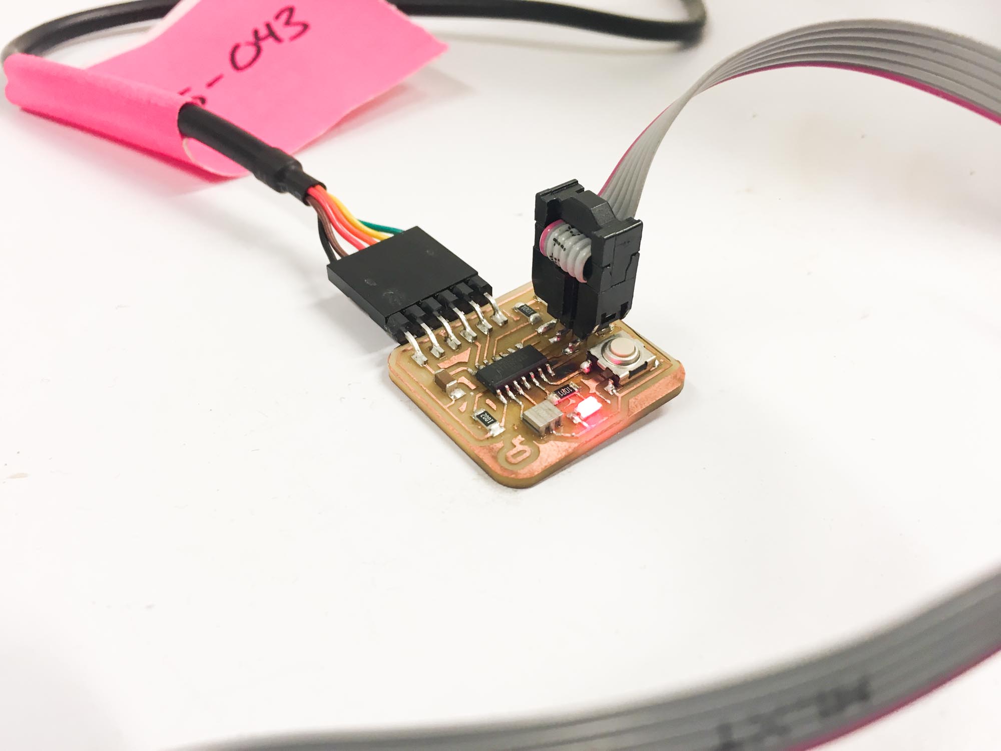
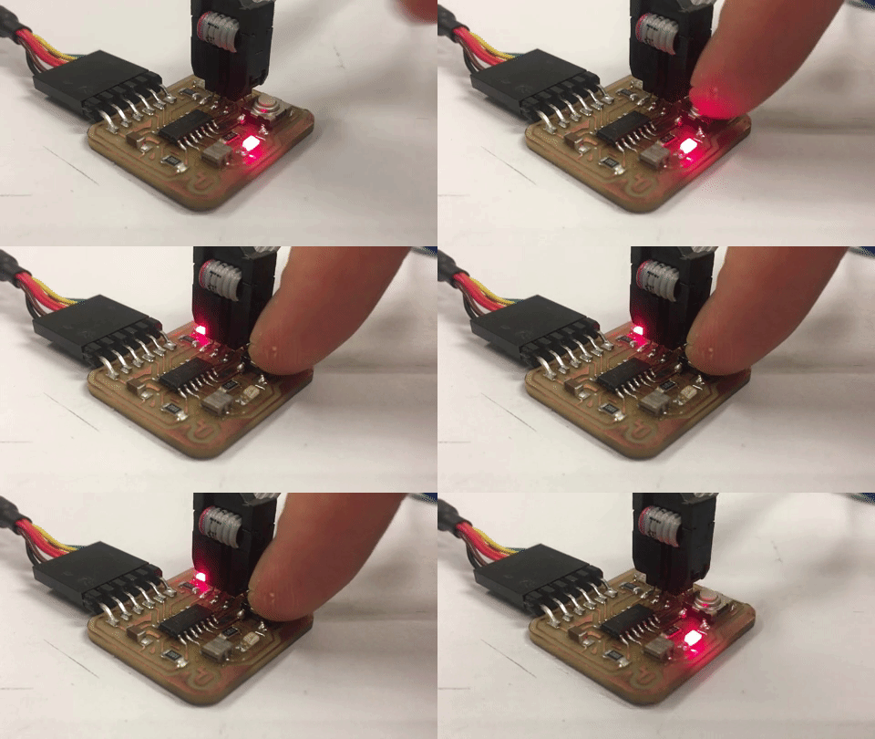
Really happy to see some interactivity action in my freshly programmed board.
Design a 3D mold around the stock and tooling that you'll be using, machine it, and use it to cast parts
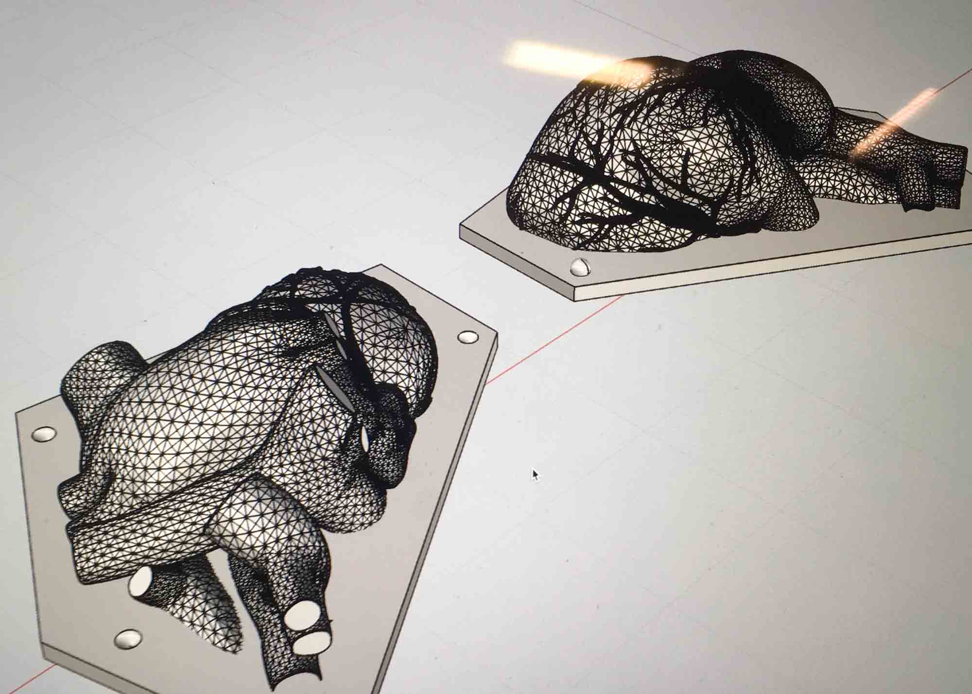
This week we are learning how to make our own molds to cast parts on. For this week, I wanted to cast a human heart to start exploring options for the final project.
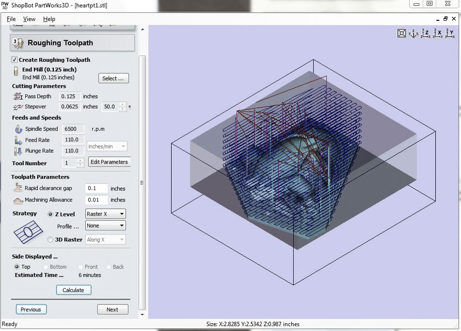
I cleaned up the 3D model, covering up all the holes and split it two parts to be able to machine it from the top. This week I used the ShopBot Partworks 3D to calculate the tool paths. I used two different tool paths for the milling process, using the 1/8 in flat end mill for both. The first path is for roughing the shape, with a 50% step over at 6000 rpm. The second pass is the smoothing pass, a 10% step over and also 6000 rpm.

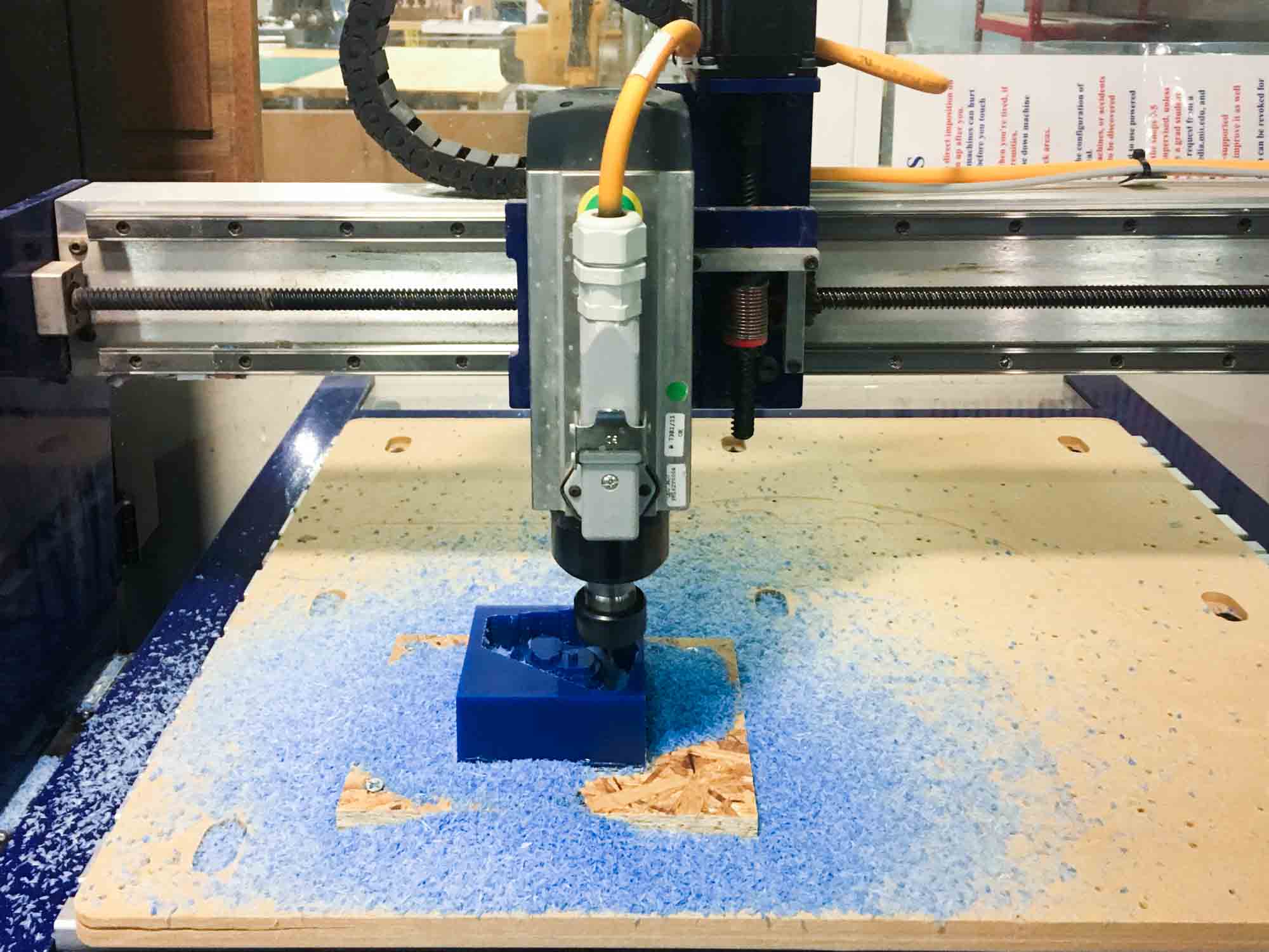
The fabrication process has three main steps: making a rigid material mold, then making a flexible mold and then casting the final product. The first step is machining a mold with a piece of wax using the ShopBot Desktop. I secured the wax block by hot gluing a piece of OSB wood and drilling that to the sacrificial layer on the Shopbot.
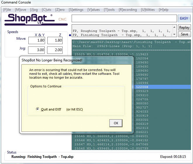
As always, unexpected stuff happened. My first mistake was importing an object that was too tight for the mold. This lead to thin walls that broke during the machining process. I went back to Rhino, scaled my model down and recalculated the tool paths. After that, I ran the job again and just before finishing, the ShopBot software threw an "error that could not be corrected". To fix this, I performed the ultimate trick, shut everything down and start it back again.

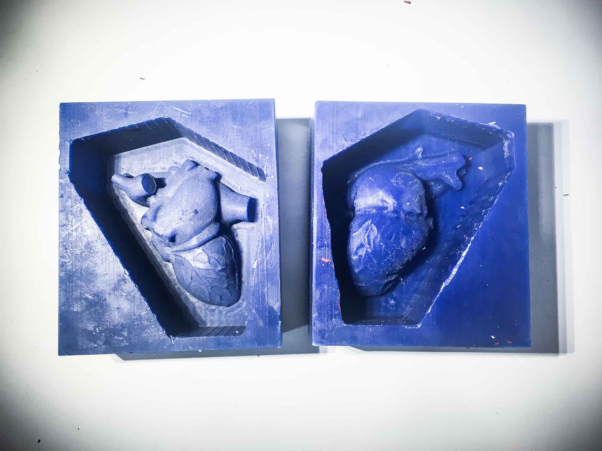
After this, everything ran smoothly and I was able to machine my rigid molds. On one of the molds, the registration marks didn't appear the same way they did in the 3D model but I decided to continue with the process.
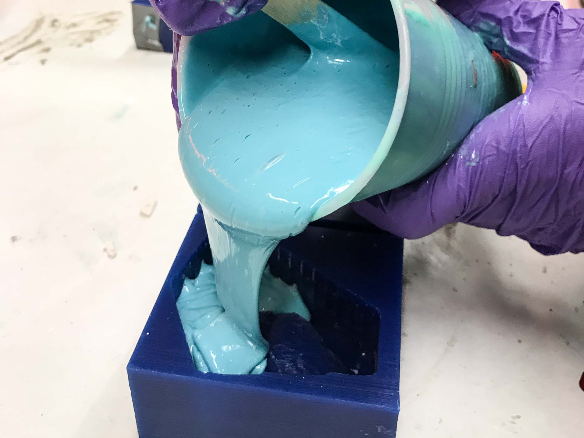
Next, I mixed some Oomoo, sprayed my mold with antiadhesive and poured it in.

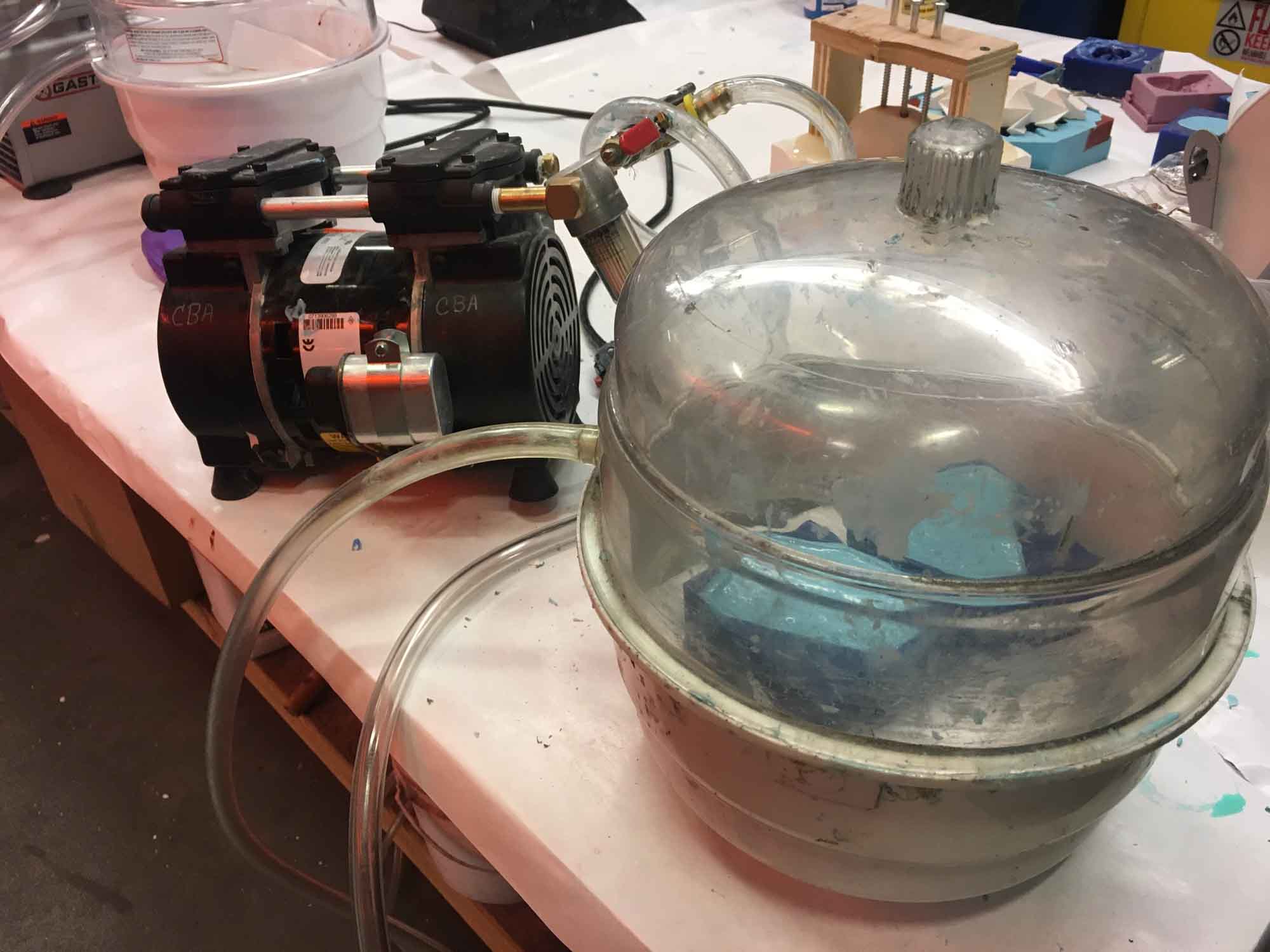
To get rid of the bubbles, I vacuumed them out using the compressor and trying to get all the air out of the mold.
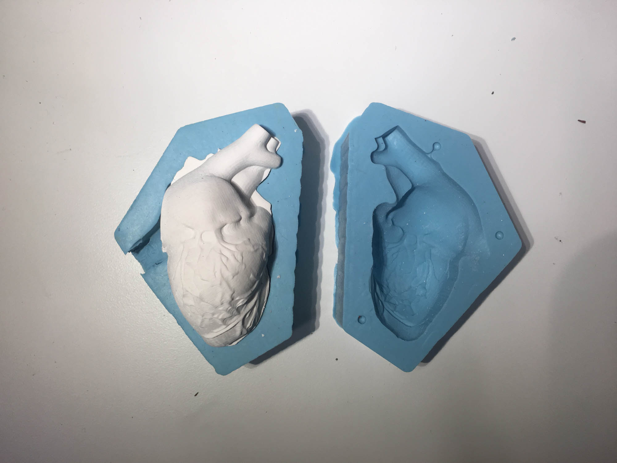
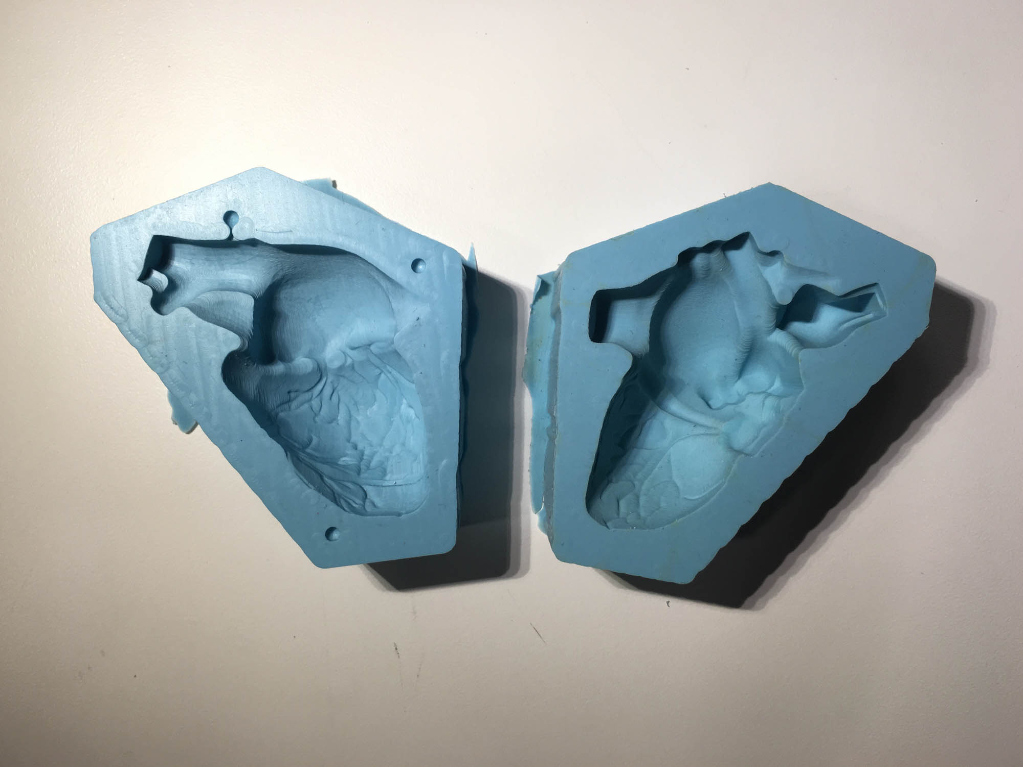
The next day, I unmolded my flexible molds. They picked up all the detail from the rigid molds, even the passes of the endmill that were hardly visible.
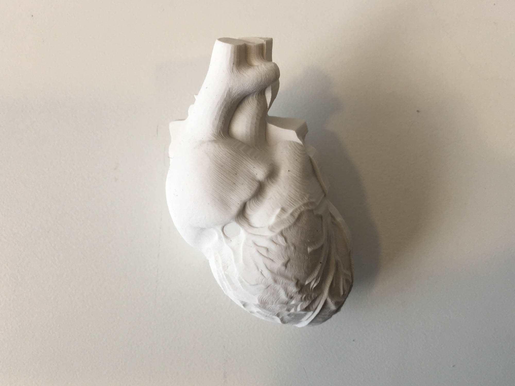
As a first step, I poured drystone to get a sense of what the volume would look like. For next versions, I should make sure the edge on the 3D model draws a line that perfectly aligns from both sides. There were some concavities in the model that when splitting in two and milling from the top led to small misalignments.

However, I think it turned out pretty good!
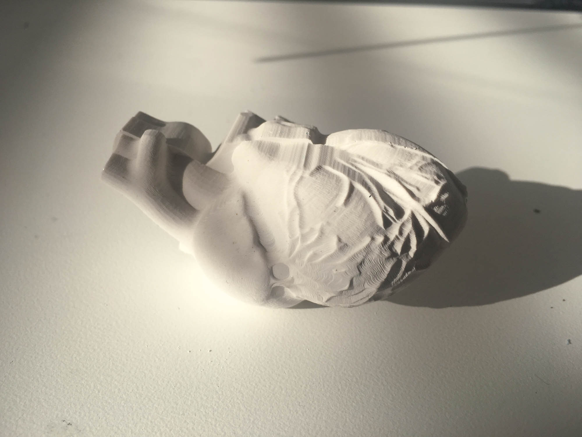
I'm especially satisfied with the veins that wrap around the heart.
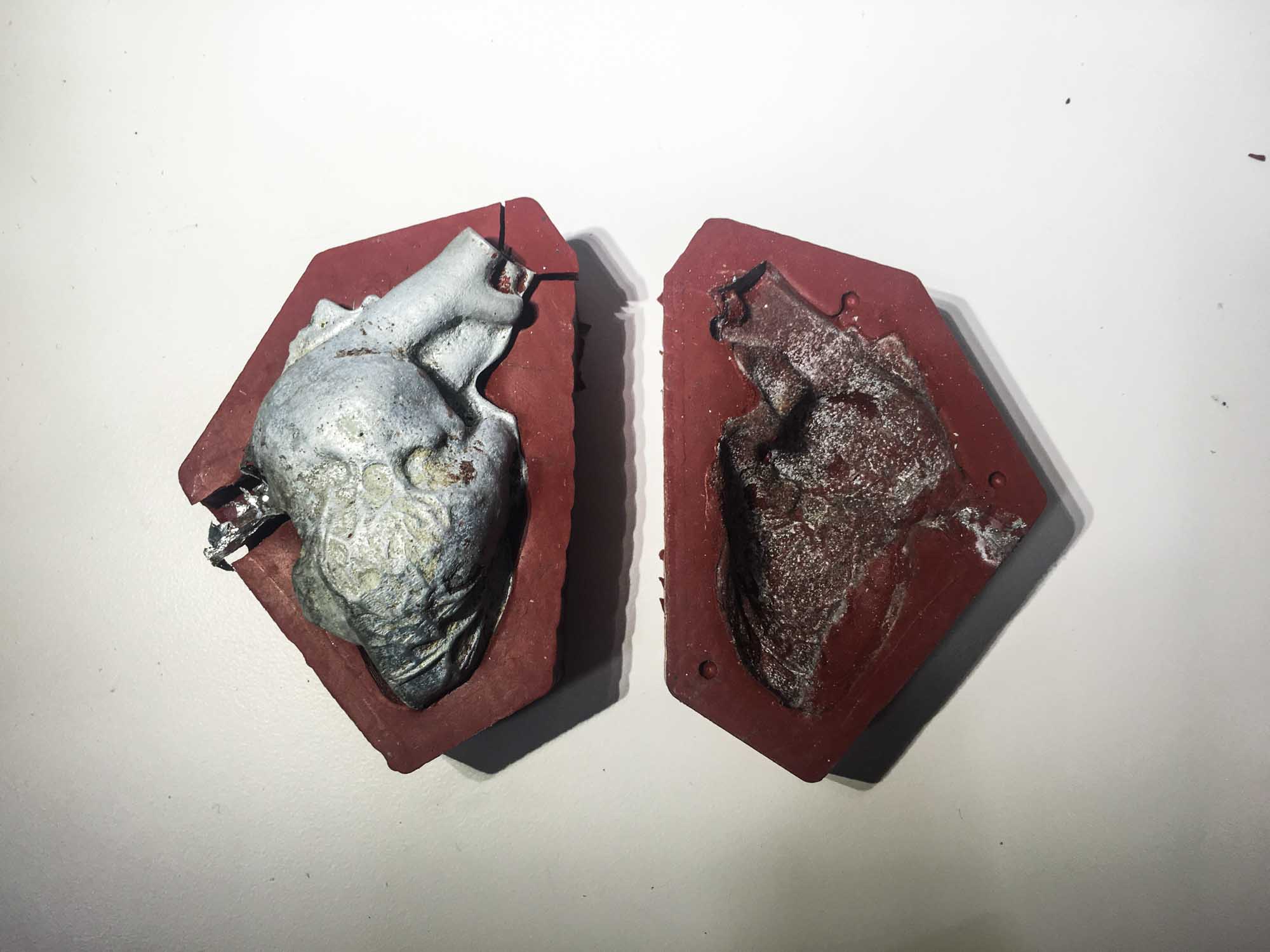
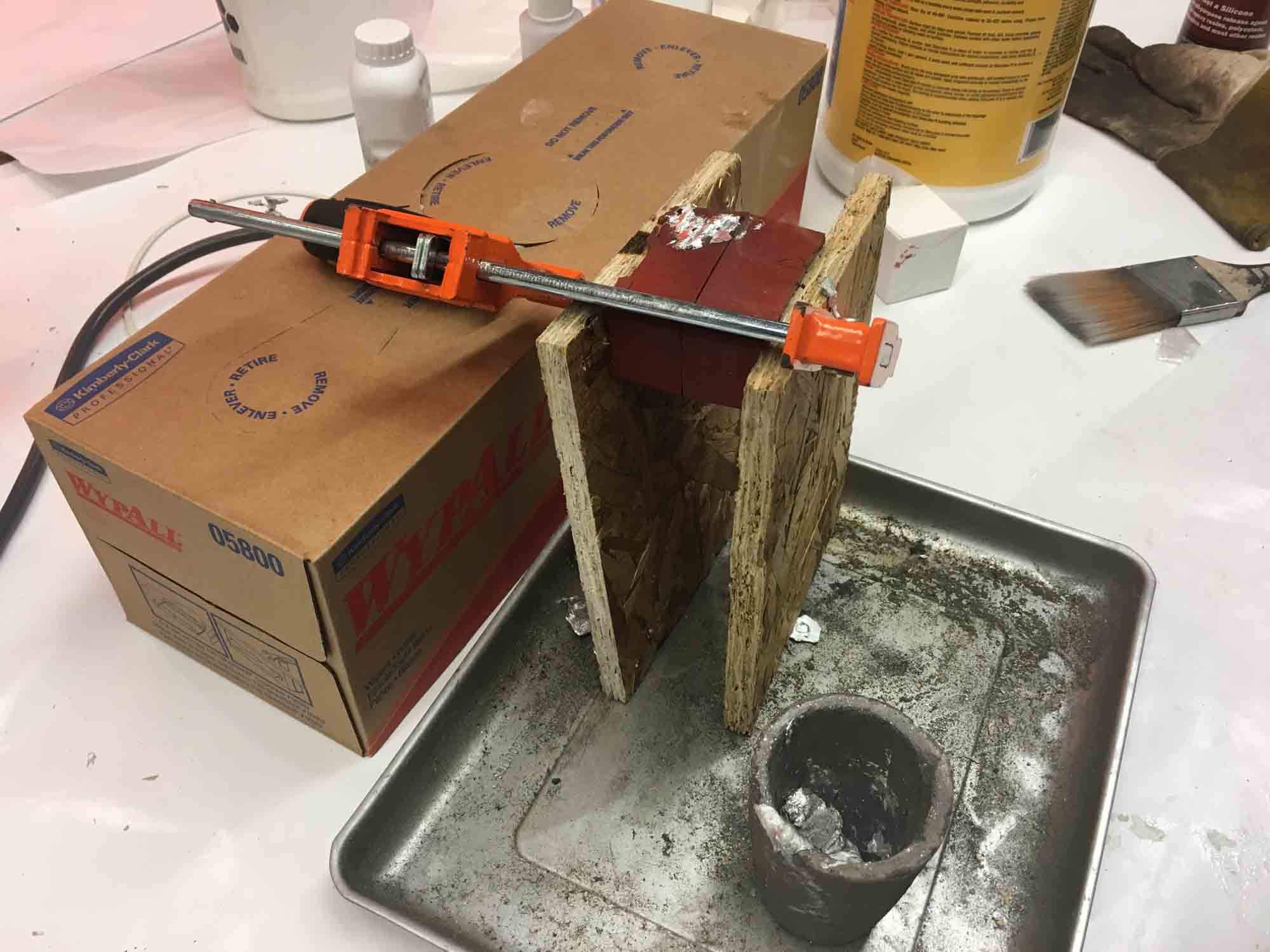
Next, I decided to cast another heart in bismuth, a low melting point metal. First, I had to remake the flexible molds, this time out of the heat-resistant red Oomoo.
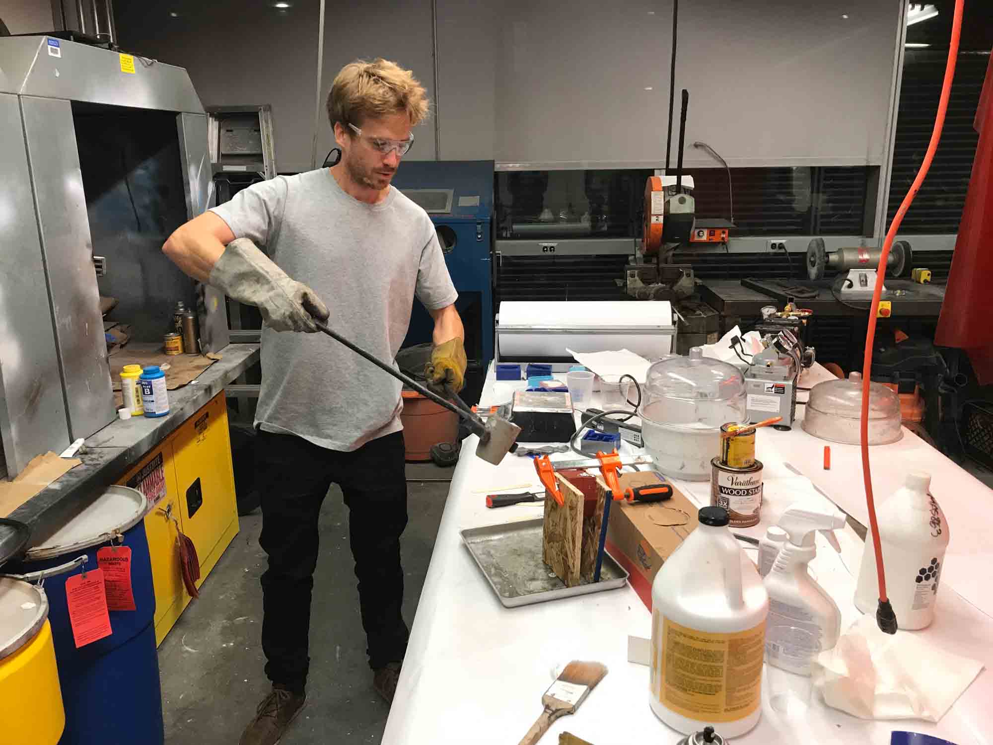
Then, I put a cup in the oven at 400 degrees Fahrenheit and waited around 20 minutes for the metal to melt. This was by far the scariest moment in the class: taking the cup out of the oven and pouring it into the mold.
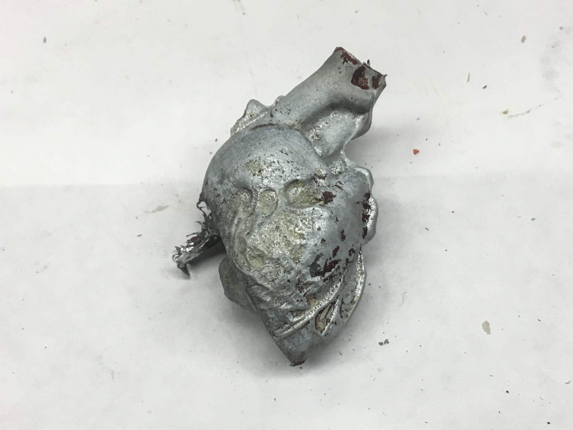
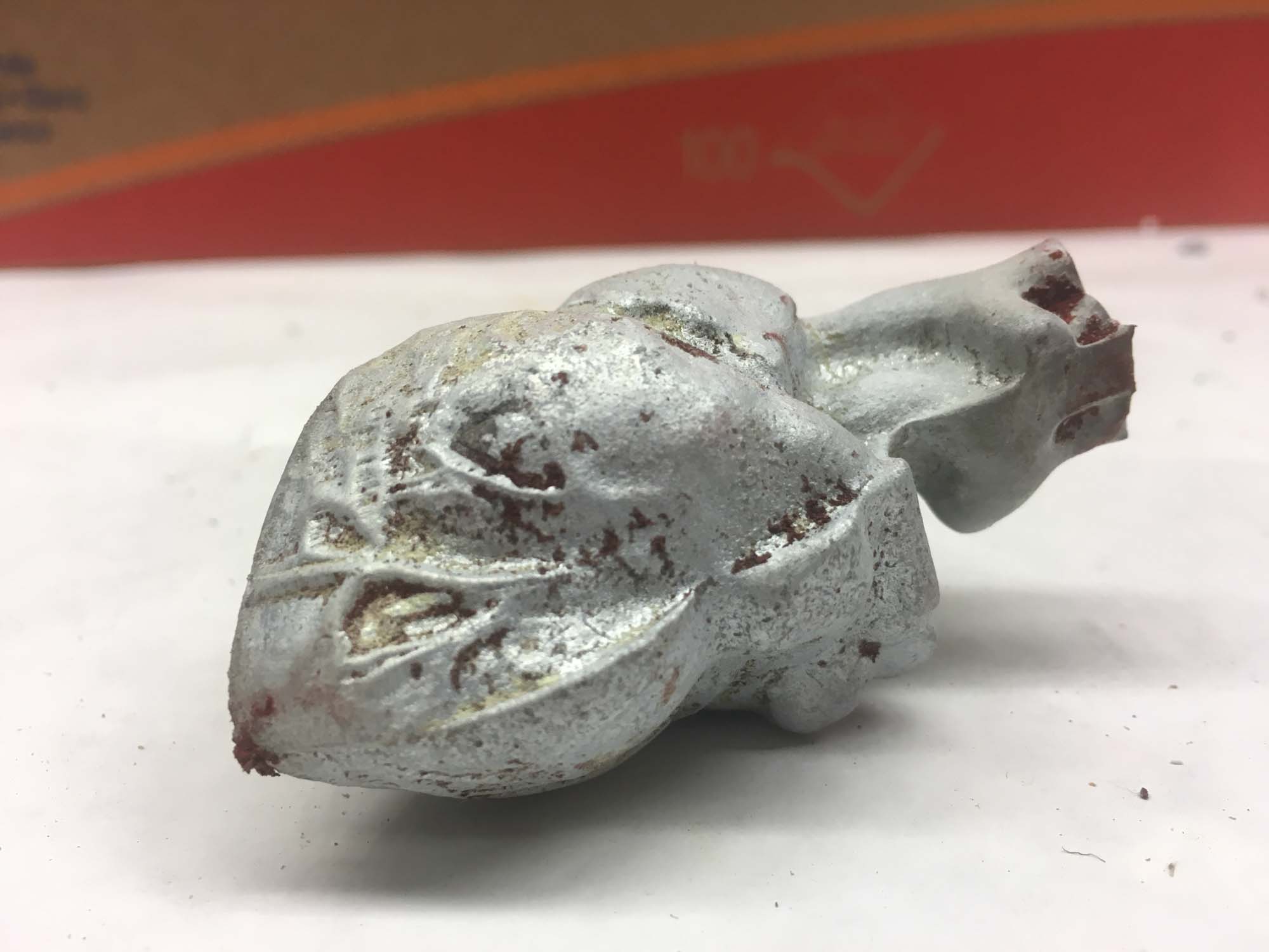
The model turned out nice, but the temperature of the metal was probably a bit too high and melted out some of the details of the mold in the process. Luckily, the model came out relatively smooth because the machining layers are no longer visible.

Tiny red pieces of the mold attached to the metal, but they add an unintentional bloody quality to the piece.
For the next version, I'm looking forward to making the heart at 1:1 scale, pouring urethane or PDMS and embedding a PCB inside.
Add an output device to a microcontroller board you've designed and program it to do something.
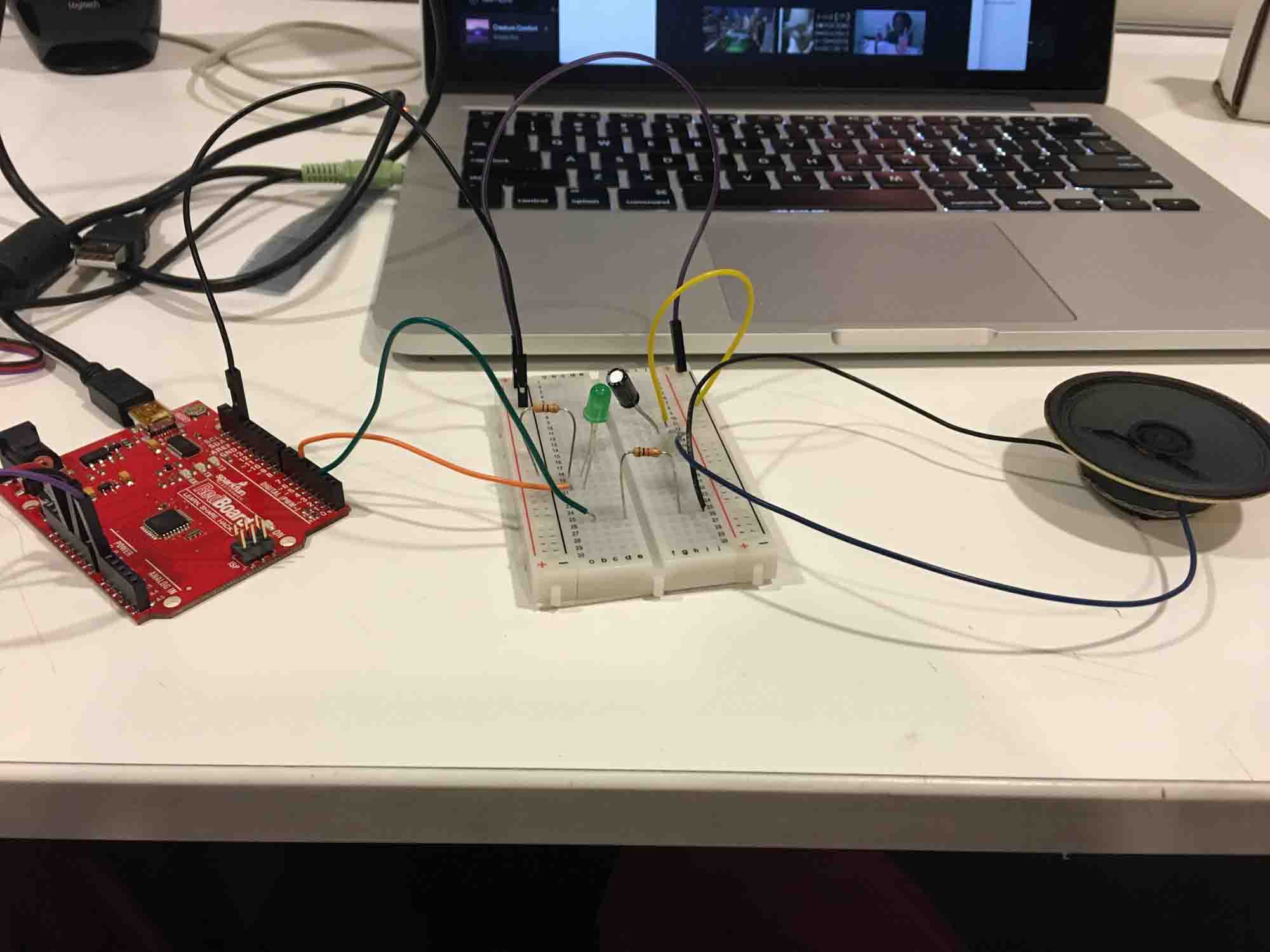
This week I'm starting to test ideas for the final project. I decided to get started by reading values from a pulse sensor and playing the peaks on a speaker. As a starting point, I decided to use a RedBoard and a breadboard to get a basic understanding the components of the circuits I need to build in the further weeks.
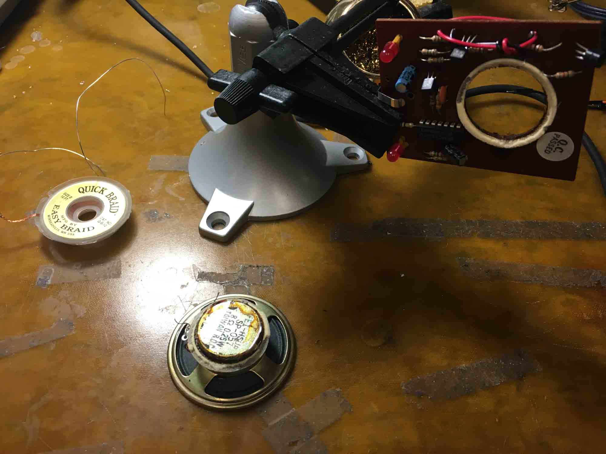
I managed to scavenge a speaker from a board that was lying around the lab. I put together a circuit and had the speaker play a tone at the peaking signals.
I also wanted to test how it would feel to make a motor vibrate to a heartbeat. For that, I designed a fabricated a simple board to drive the motor.


The board was vibrating nicely, so the first step towards making an autonomous board was complete.
The final actuation board will read data from the heart rate sensor board and vibrate acccordingly. For the final project I worked with the RFD22301 chip, mainly to facilitate networking and to make a board that was small enough to fit in my heart model which was at 1:1 scale. Tomas helped out in the design and debugging of he hardware. Thanks man!


I programmed the actuation board to read values from my computer and actuate the vibration motor and an LED on the board.


Plan and make a machine.
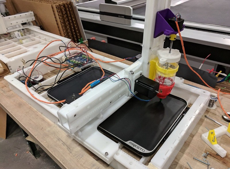
This week all the CBA section is teaming up to do a project. After brainstorming a few ideas we decided to make a CNC pancake printer! The idea is to make a machine that can print custom pancakes from input images, using grayscale information to decide the order in which pancake batter should be placed on the griddle.
The idea came from pancake art videos on Youtube. After seeing this we thought it would be a fun idea to try to build a machine that mimics what pancake artists do.
To build the machine we've split into 3 sub teams, who will be dealing with different elements of the fabrication process. Our overall concept is an x-y axis 'plotter' that squeezes batter onto a hotplate. By timing the batter output, we can achieve a variation in color, enough to produce a simple grayscale image. In order to ensure even cooking, we're using a hotplate we bought online, though an obvious improvement would be to integrate the hotplate into part of the electronics subsystem. My contributions for this project where around the mechanical engineering required to make the machine move.
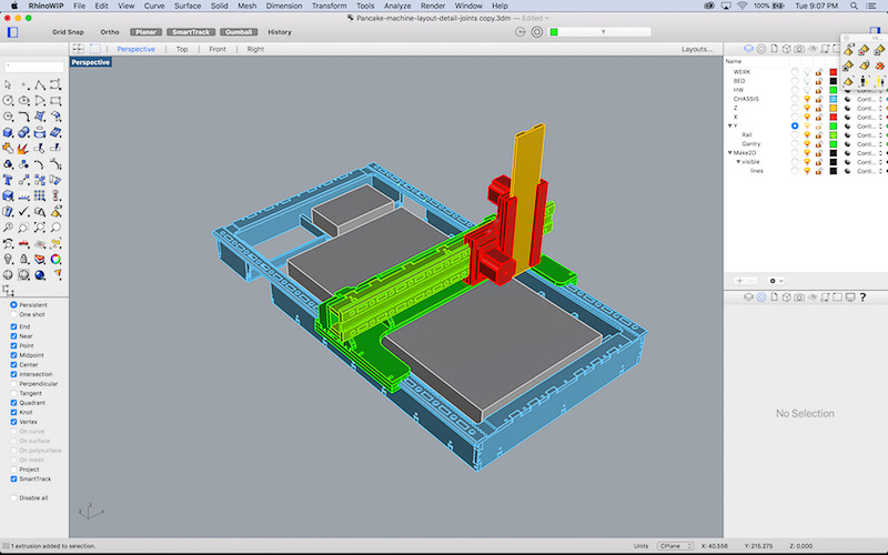
I spent some time trying to understand how the 3-axis system plotter worked. Then adapted the dimensions of the machine to fit our griddle. The first step was drafting the overall layout of the machine, to get a rough sense of the overall dimensions of the machine. After that, I used each of the grasshopper files to calculate each of the axis and overlaid it with the model.
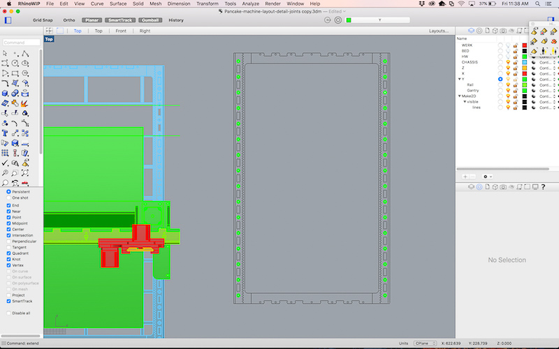
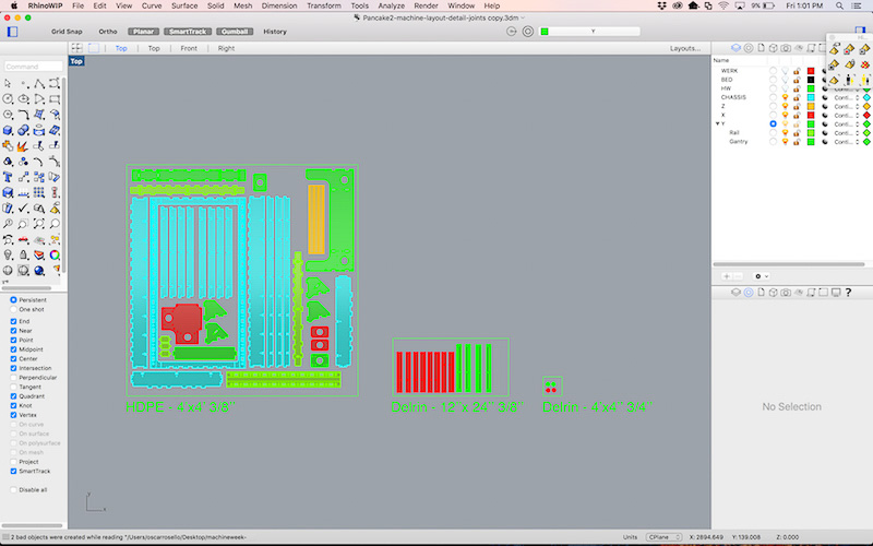
Once everything was fitting, I laid out the pieces in a 4x4ft HDPE sheet and handed the design out to the machining team to calculate the toolpaths and cut them using the ShopBot.
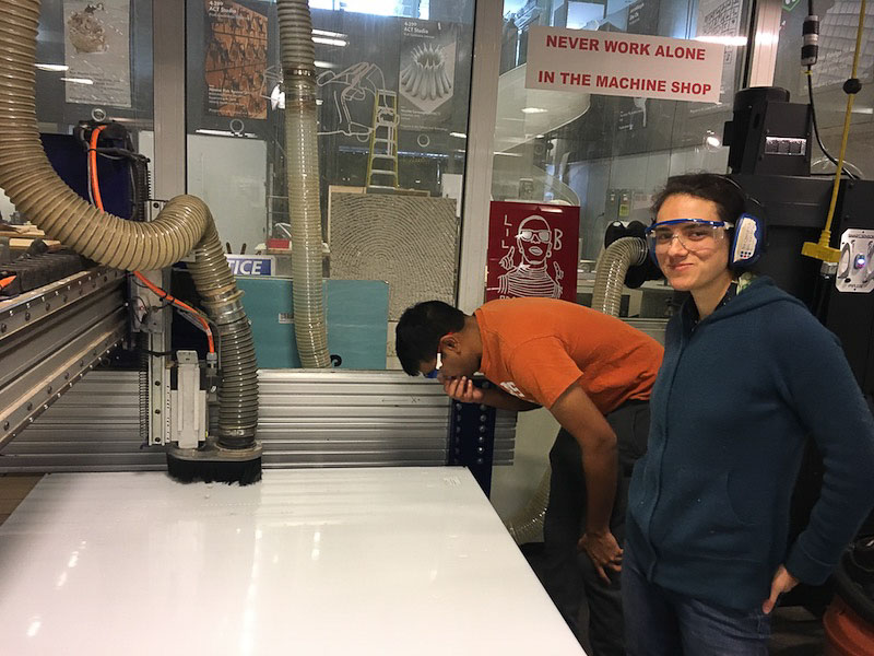
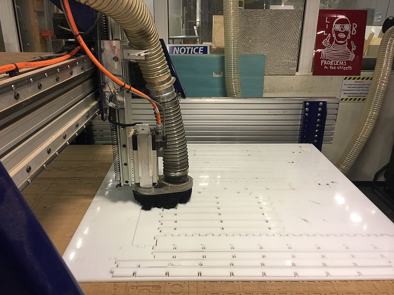
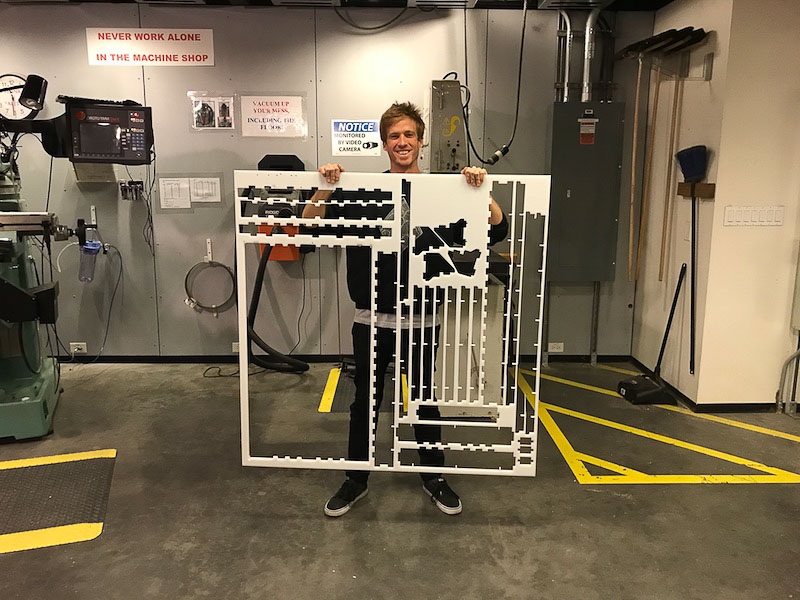
All the mechanical components fit into a single 4x4 HDPE plastic sheet. Next, I worked on the assembly of the machine together with by Vik, Safinah and Yun.
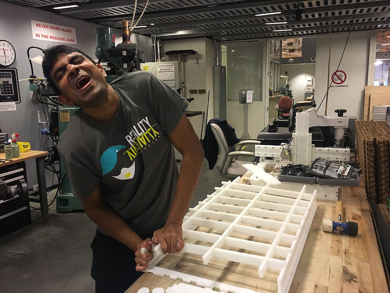
We started with assembling the base the night of the milling. When we attached the walls to the base the whole machine wobbled. Next morning we decided to let go of the vertical beams as the base was pretty stable on just the walls and the horizontal short ribs. We then made the top two parts, one that holds the y-axis motor, and one that holds the end effector.
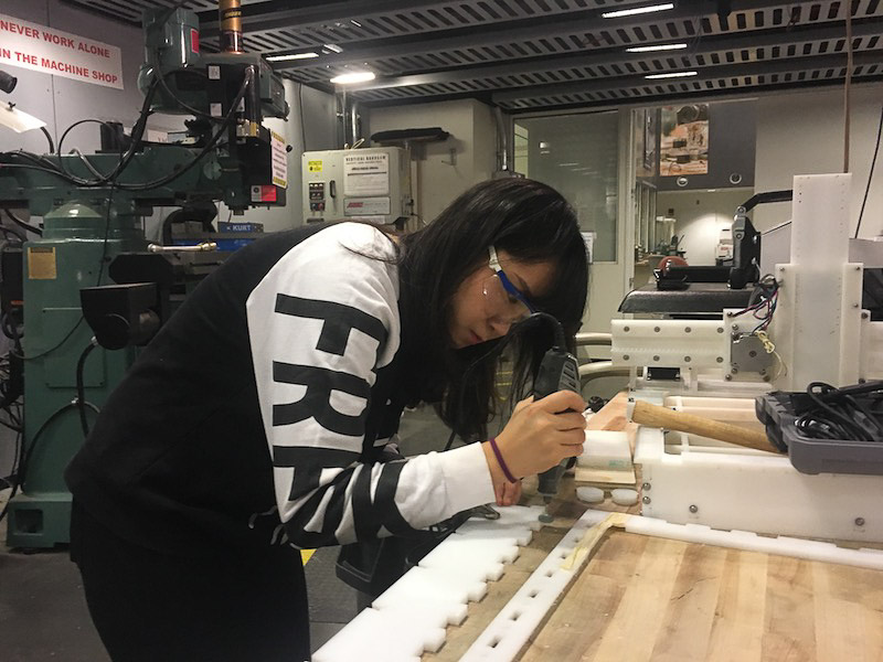
We had to use the dremell to sand off some of the press fit joints to be able to fit them together. While inserting the y-axis part along with the end effector on top of the horizontal base, we realized that it was getting to heavy and bending the whole thing down towards the base - so we had to nail in the triangular parts to the vertical walls of the y-axis motor part. So as you can see we drilled in extra holes using a hand drill, and put in nails to hold the y-axis motor and end effector in place. We also realized that the pinion was not touching the teeth of the sliders, so we had to remove and move the motor slightly up by half an inch and drill new holes.
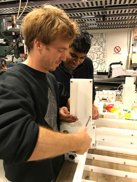
We then put together the end effector part. We needed some amount of removing and glue gunning or the corner yellow triangles since it was tough to hold them in place. Throughout the body we did a lot of extra nailing to be able to hold the body parts together. We tested out all the 4 motors in the physical structure. The z-axis motor did not work. We tried to troubleshoot by replacing the y-axis with the z-axis extruder motor, and it worked. So, we realized that it only needed reconfiguring of that motor.
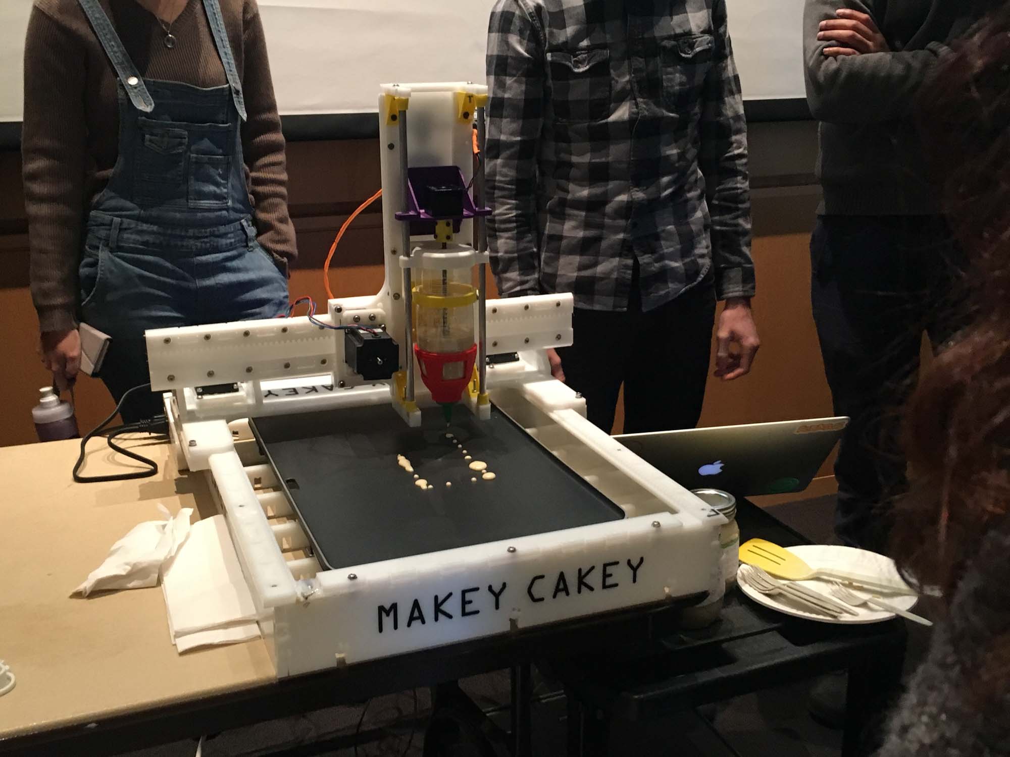
After configuring it, all the axes worked and the machine was fully functional!
Measure something: add a sensor to a microcontroller board that you have designed and read it.

This week I'm building a basic board to be able to read values from a pulse sensor. As a starting point, I took the design from the board I designed in week 5 and modified it to be able to read the sensor values.

Laying out the schematics was straight forward: I just connected teh sensor component to the 10th pin of the microcontroller and then also to 5V and ground.

Adapting the board to have the three pins required some retracing gymnastics. Eventually, I decided to solder a 0 Ohm resistor to be able to bridge the sensor signal while keeping it connected to power and ground.
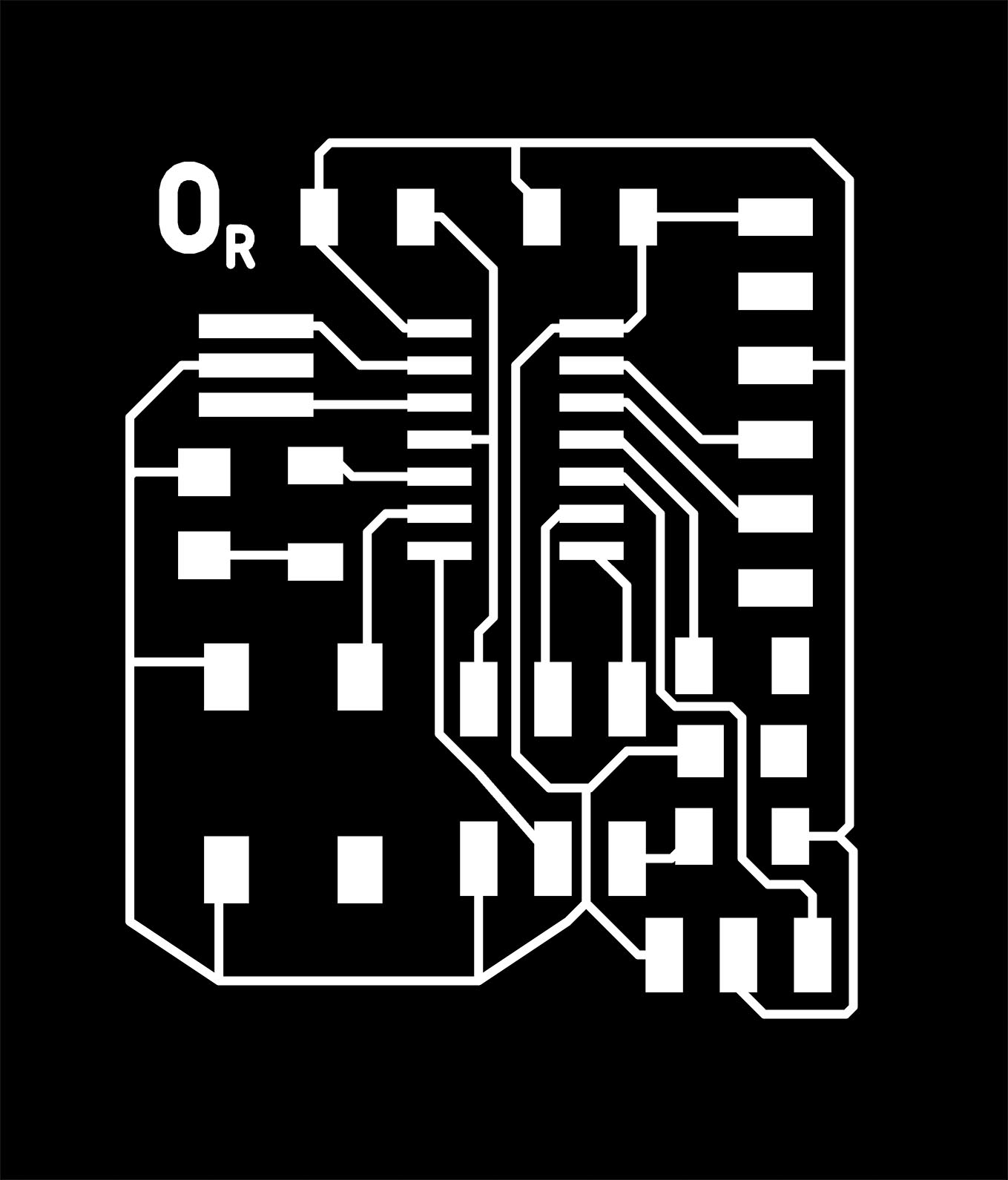
Next, I exported the .PNG from Eagle and imported it into Mods for machining the board on the Modela.
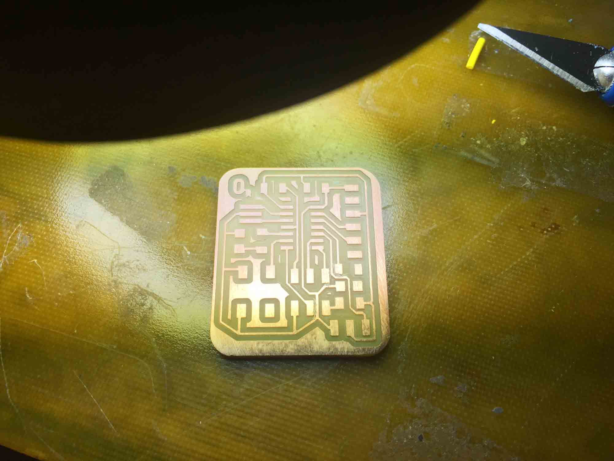
As usual, there where a couple of places where the pads where touching with the traces and had to clean up the board with a blade to make sure all connections looked fine before stuffing the board.
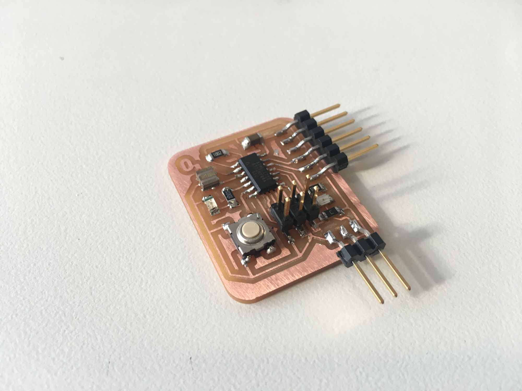
This week we learned to reflow solder during recitation, so I decided to give it a try with the oscillator. It's a really nice feeling to feel the component drop once the metal melts and all connections are fixed in place. Next, I plugged in the board but I had odd communication coming back from the microprocessor when testing an echo program.
First step was visually inspectig the board to make sure all the components were correct. I wasn't able to read the values from the capacitor, so I decided to replace it. It still didn't work. So, I decided to replace the oscillator, as I suspected that perhaps heat had damaged it during reflow. Still not working. Then, I decided to replace the microcontroller and give it a try. Still no luck! Finally, the problem turned out to be a trace that was too thin and wasn't conducting properly. To solve this, I thickened the trace with solder and the echo program loaded just fine.
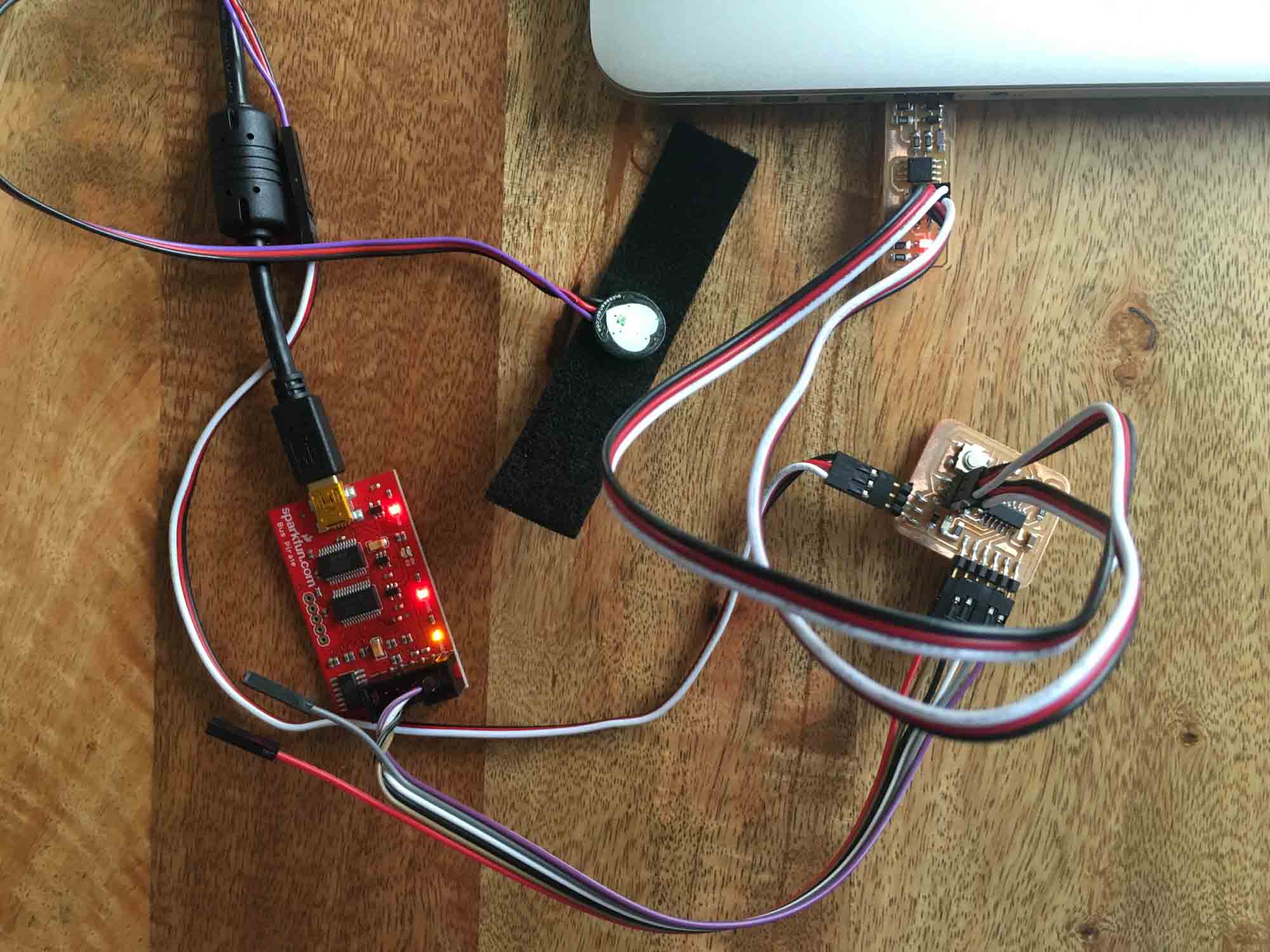
I was away during the weekend, so I didn't have acces to the tools on the electronics shop. So, instead of using the AVRIP mkII programmer I used the USBtinyISP I built in week 3. I also didn't have access to an FTDI cable, but managed to get a hold of a Sparkfun Bus Pirate and used that as a USB serial interface.
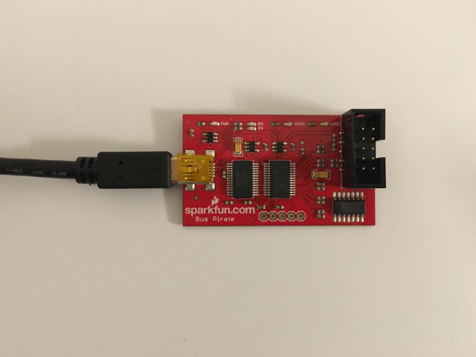
Learning to use the Bus Pirate took some time (thanks Pol). After all connections were in place, the correct mode needs to be set using terminal and also power it using 5V. Eventually, I managed to load the echo program and the blink LED program on the new board.
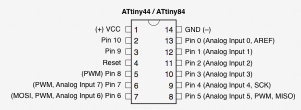
As a starting point, I took the code from week 7 and modified it to read the values from pin 3 (analog input) and blink an LED at peaks.

Then I spent some time playing with delay values and plotted the data from the sensor in 2 axis. The sensor takes some time to stabilize, but after a few seconds the signal displays nicely on the plot. The code can be downloaded here.
The sensor board needs to sense data from a heart rate sensor and stream it via Bluetooth to the actuation board. This board is just a variation on the actuation board that I designed earlier.


I programmed the sensor board to read values from the pulse sensor and send them over to my computer via the usb serial port.


Write an application that interfaces with an input or output device that you made.
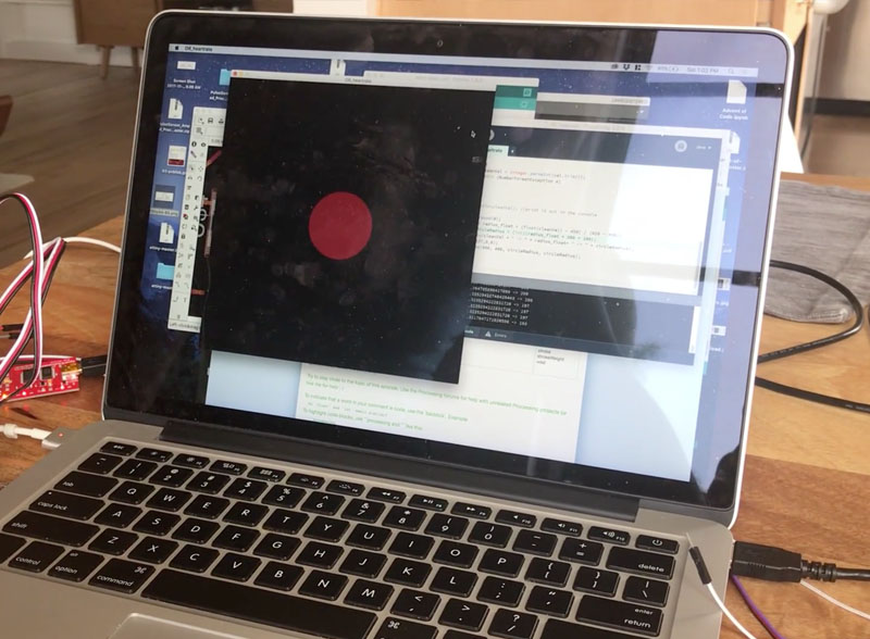
This week I will be making a simple app that reads the values from the pulse sensor board I made last week and displays a graphic representation of the sensor data. To to this, I used the Processing environment for the interface, a collection of libraries for Java.
The overall idea for the application is the same as the concept for the final project. I'm interested in giving the user real time feedback of biometric information, pulse in this case, and understand how that can alter their behavior. This means, that I'm not interested in displaying specific values that the user needs to interpret after, but give the user certain guidelines that can help them alter their state.
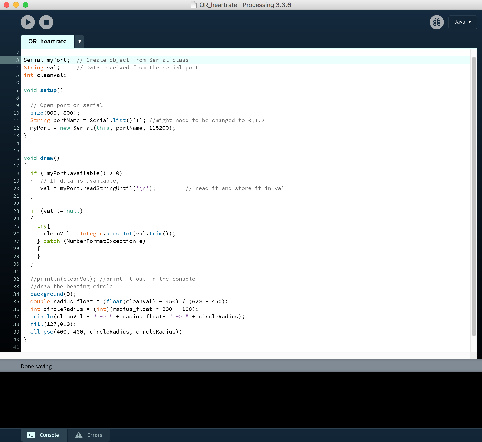
The implementation was straightforward. I open a port for serial communication and store the values of the sensor. Then I scale those values and map them to the radius of a circle that changes in real time. The code can be downloaded here.
I tested different variations with the scaling of the circle, some delay values and color gradients.
Finally, I settled for a sublte shake of a red shape on a black background. I tried different breathing patters while connected to the app to get visual feedback on how the shape changes.
Design and build a wired or wireless network connecting at least two processors.
The communication between the boards was done over Bluetooth using the Gazell protocol.


The sensor board reads the values from the pulse sensor and sends them over Bluetooth to the actuation board that vibrates in sync with the pulse. Also an LED blinks when the board vibrates.
Design and fabricate a 3D mold and produce a fiber composite part in it, with resin infusion and compaction.
This week I built a composite skateboard deck. I was interested in testing out how much concave I was able to add to the board, as conventional skateboards are made out of layered maple and the concavity of the board is limited by the material properties.
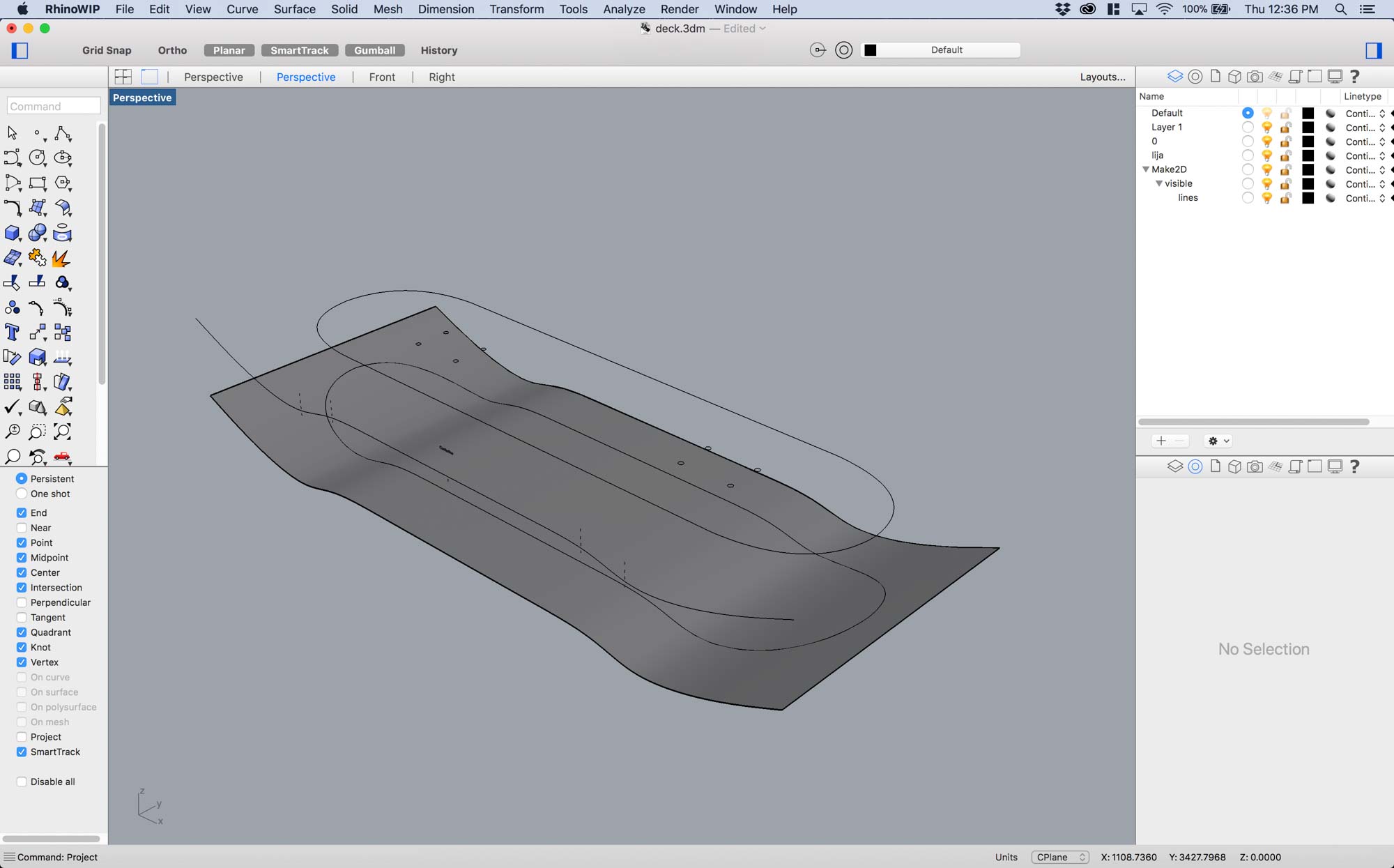
I modelled everything in Rhino. I drew a profile curve, extruded it and then projected a skateboard outline onto it to draw the deck shape.
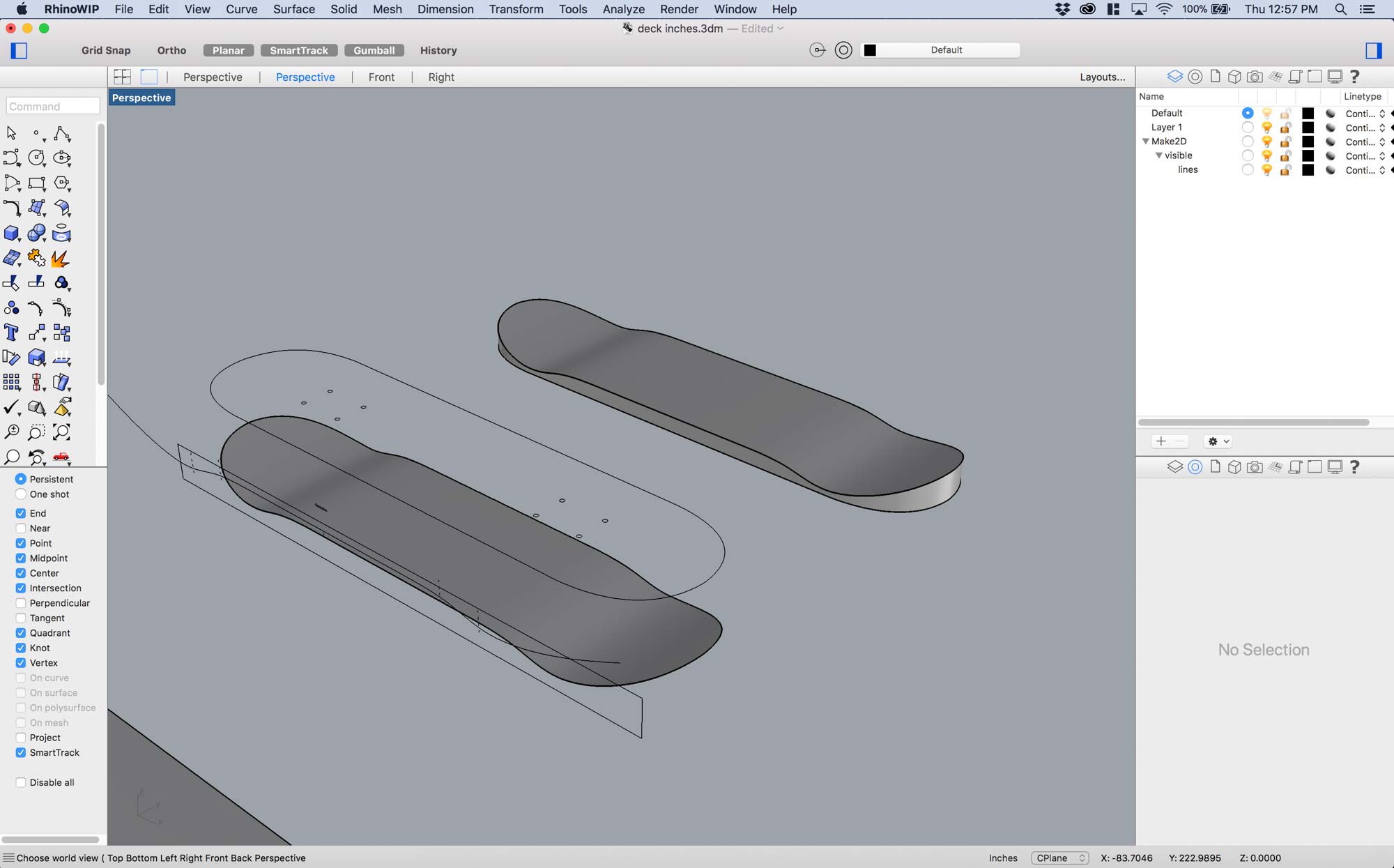
After, I took the top profile and drew supports on the sides and a flat bottom to design the mold I would lay the composite in.
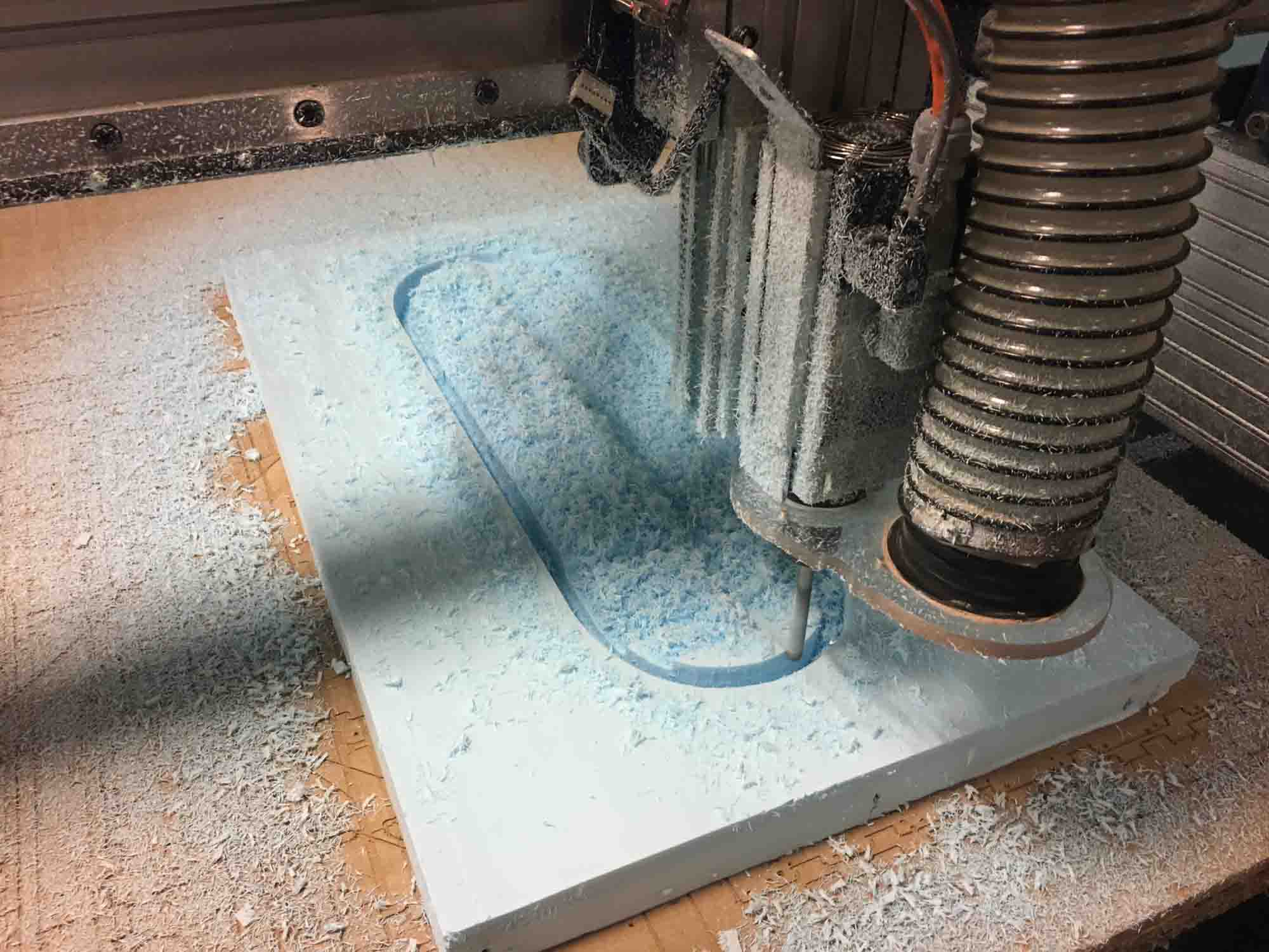
Milling was a quick process this time. I feel like I'm starting to master the Shopbot and it almost does what I want it to do. The mold was milled using a 1/4 inch drill bit from high density polyethilene foam.
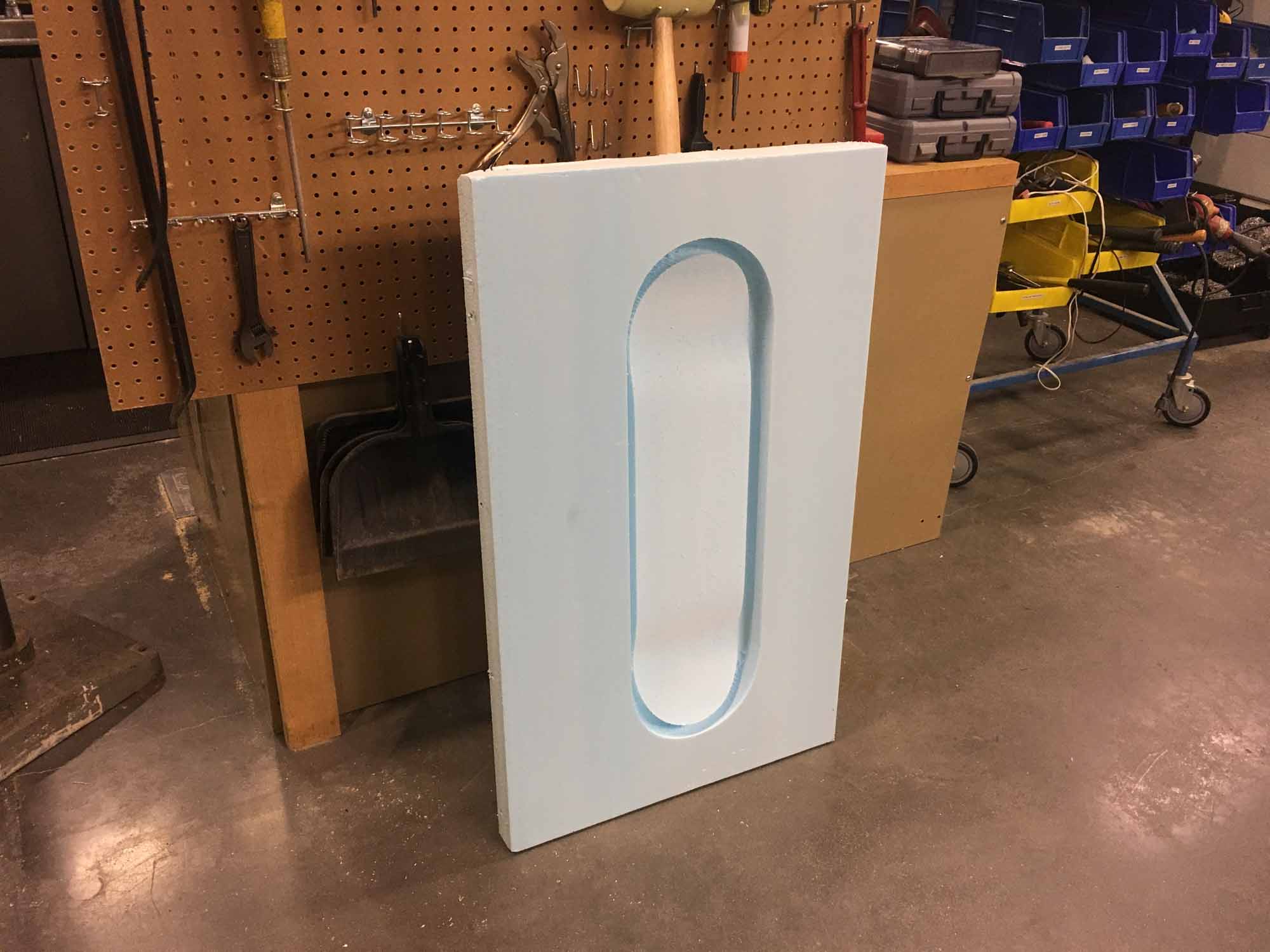
The mold is now finished and ready to start laying out the composites.
Grace taught us how to use the Zund robot to cut the layers of burlap that would go on our composite.
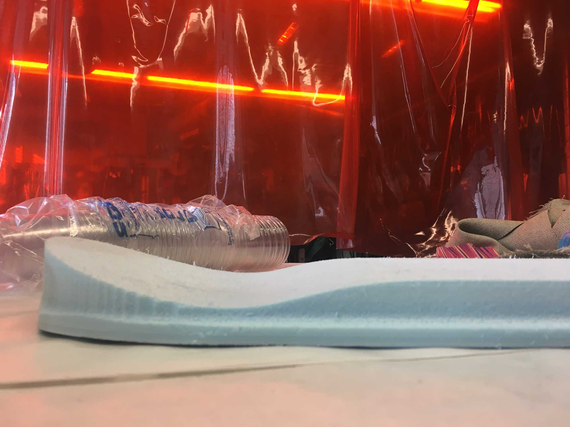
The concave shape of the mold is much deeper than any conventional wooden skateboard.
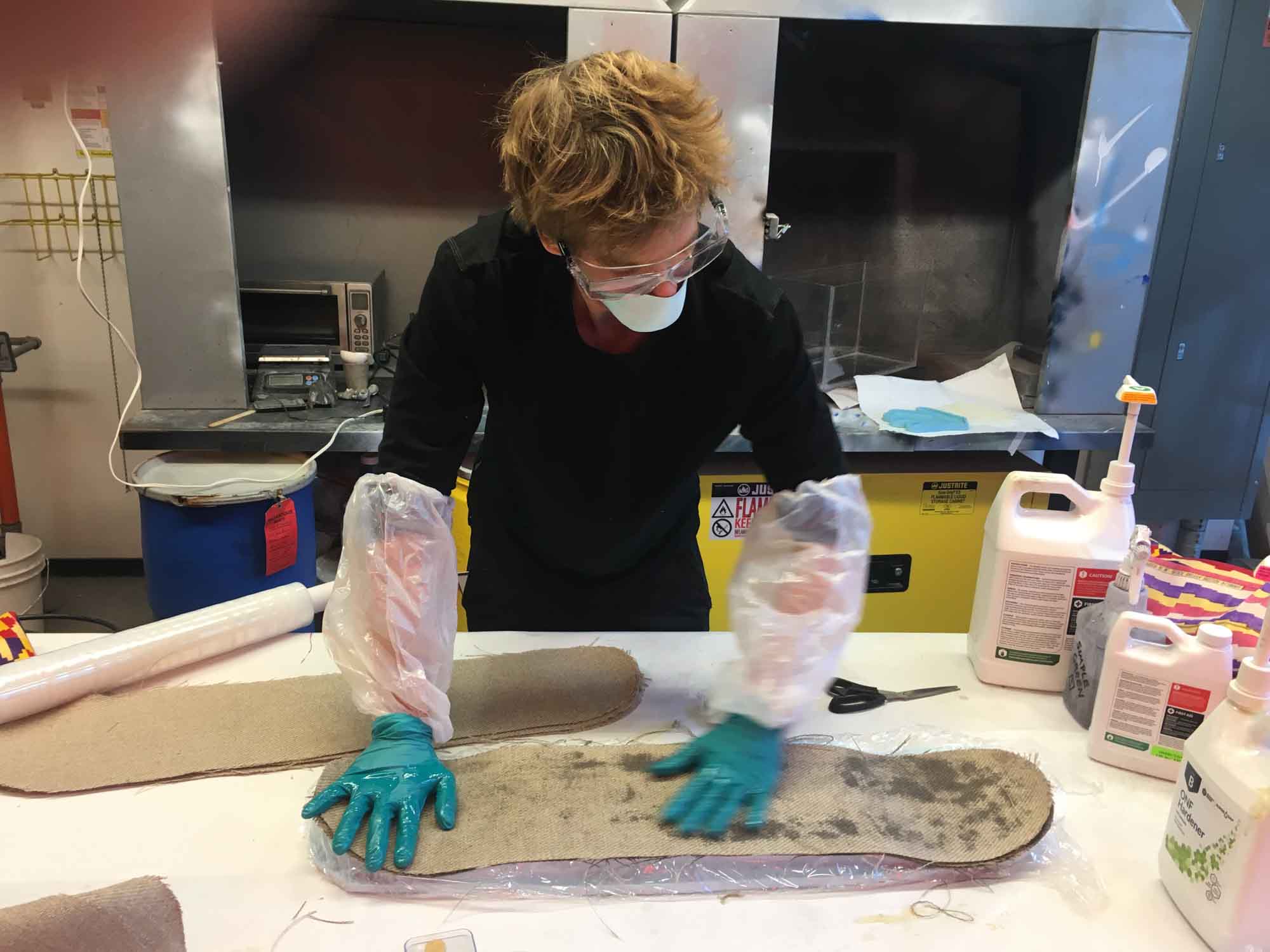
Laying up the composites was fun. We had to work quickly because the exothermic reaction of the expoxy heats up the material to the point where it burns the hands.
This is a timelapse video of the composite layup process. I layered 9 layers of burlap plus epoxy resin in between. To protect the mold, I put a layer of plastic wrap. Then, after all the layers were set, I wrapped the composite in plastic and made tiny holes to let the excess Epoxy get out. After that, I wrapped the whole thing in a textile bleeding layer that would hold all the excess epoxy.
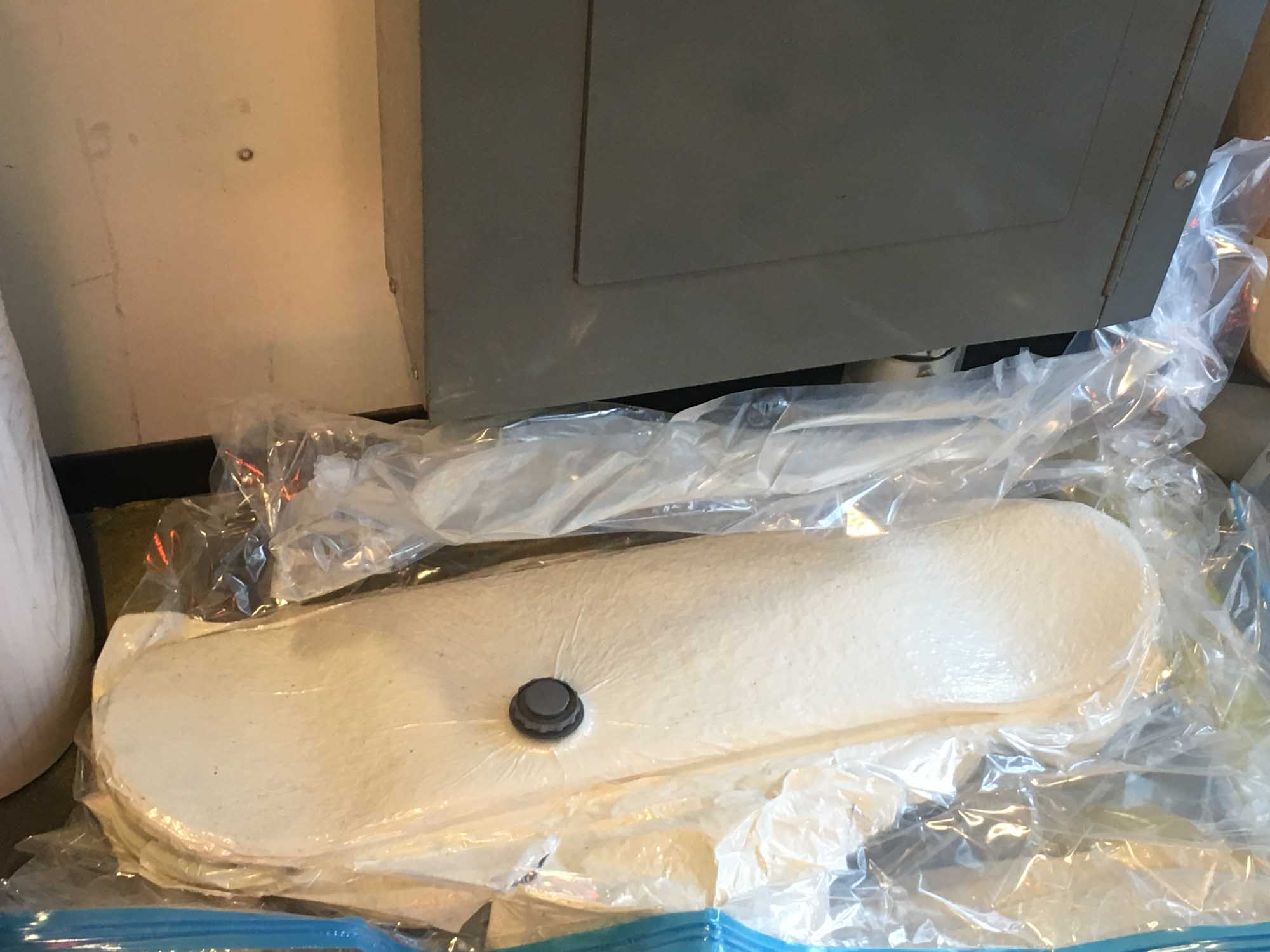
After that, I put everything in a vacumm bag to add even pressure and let it sit overnight.
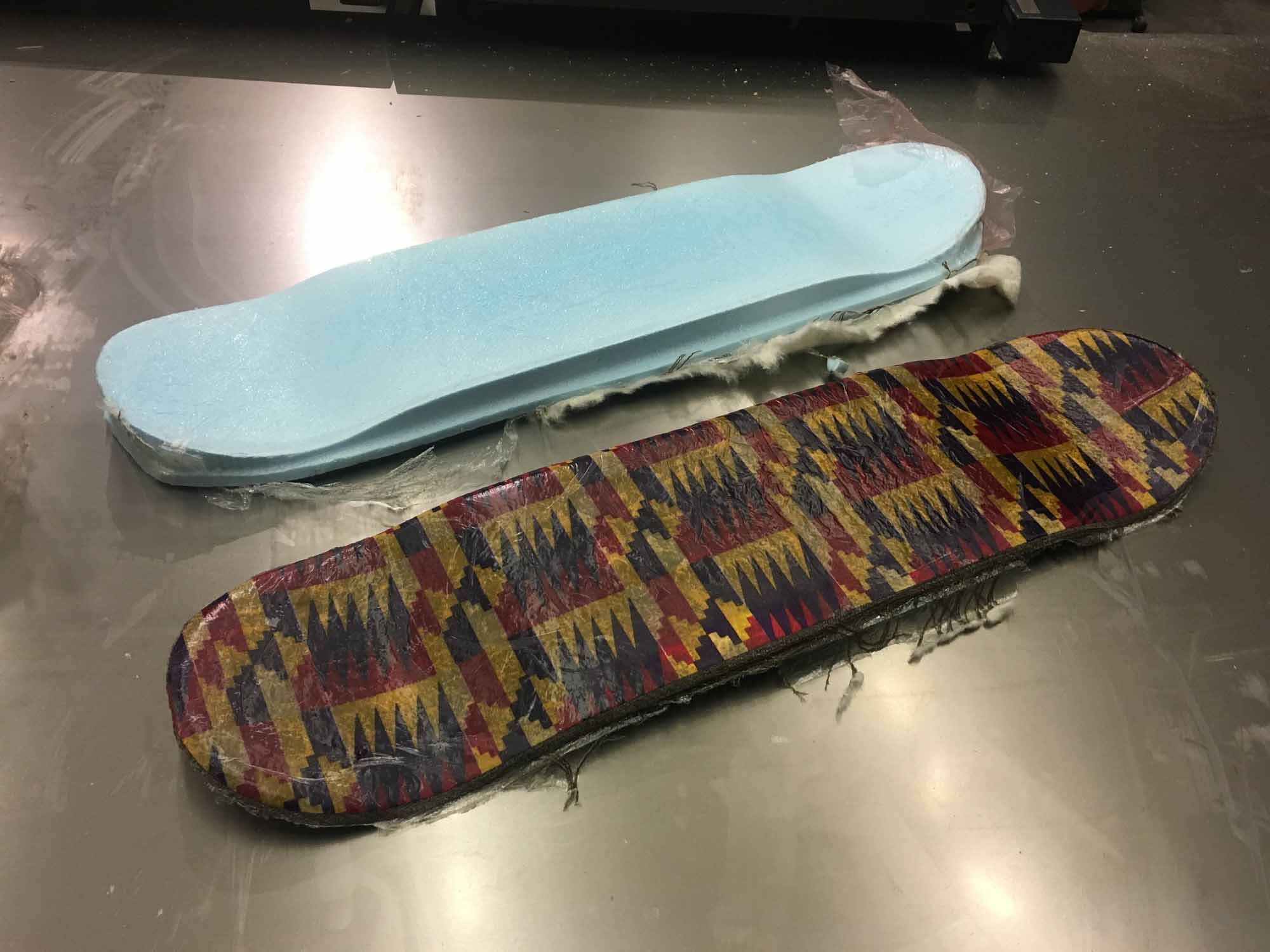
Demolding was straightforward, the composite came right out of the mold without any problems.
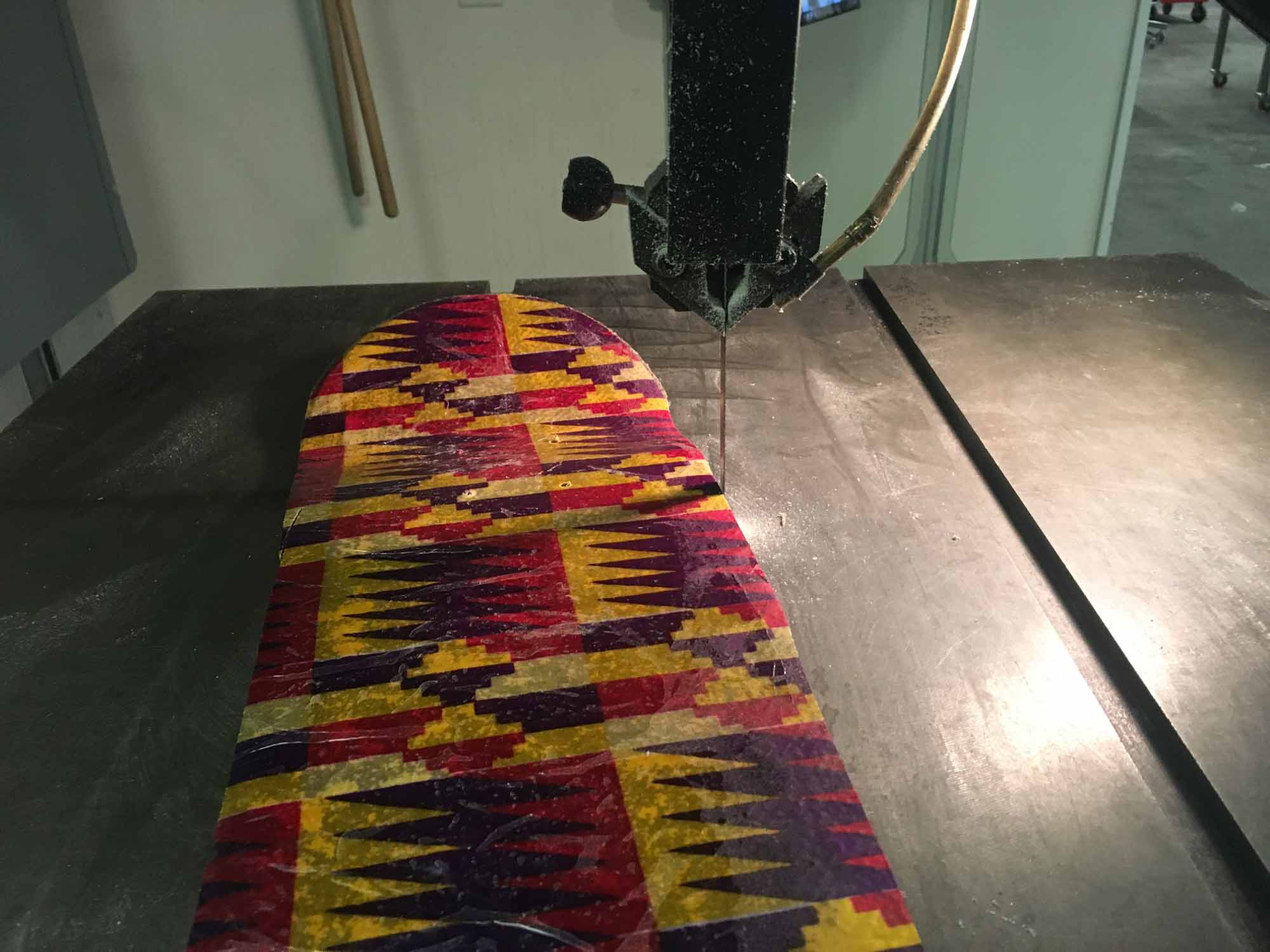
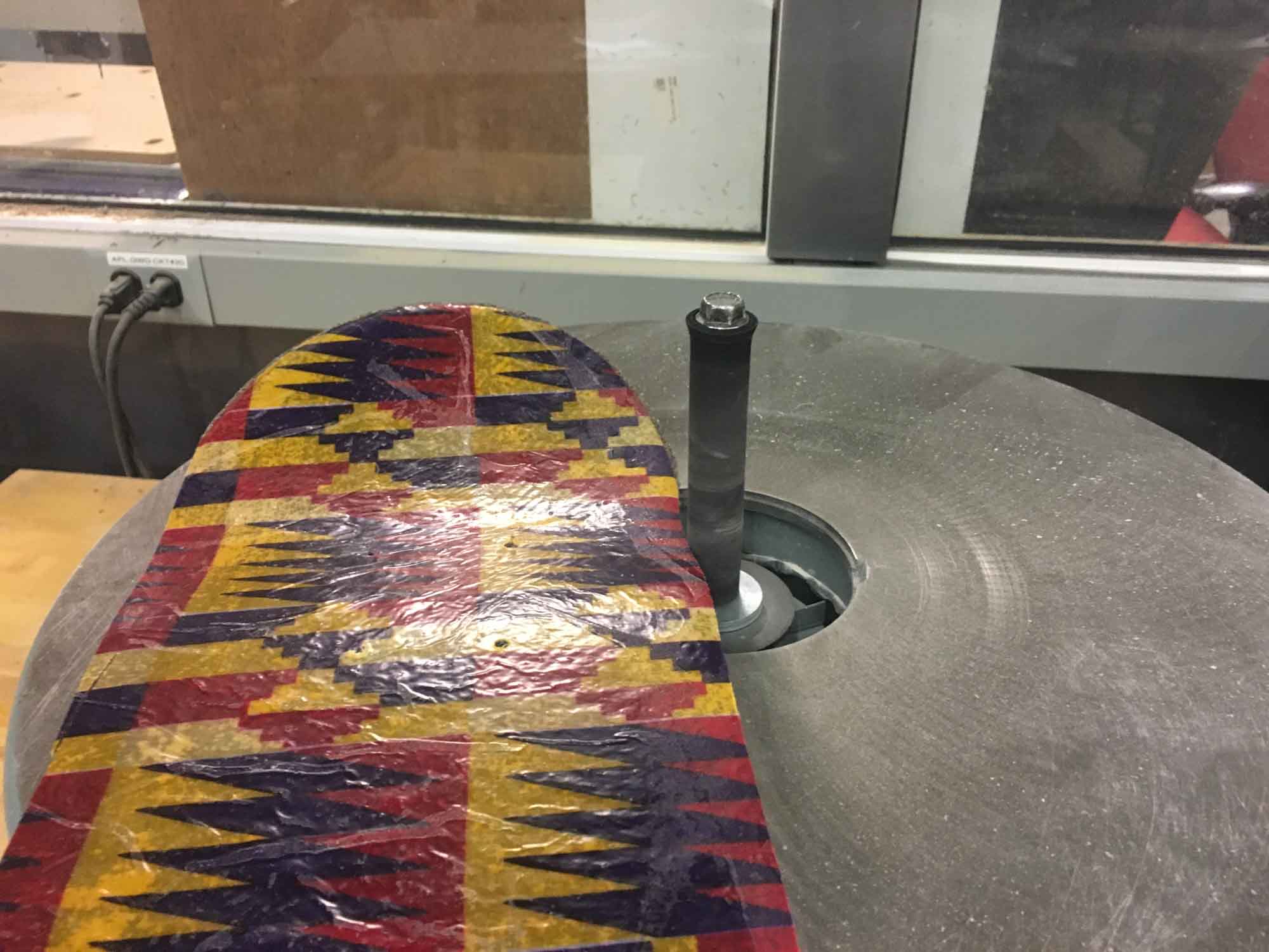
I cleaned up the edges with the bandsaw and sanded them after to get a smooth finish.
The skateboard is fully ridable and very resistent. Next iteration I would use less layers of burlap (maybe 6 instead of 9) to reduce the weight of the board. At the moment, it's about the same weight of a conventional 7-layer maple skateboard, so making a composite one might be an opportunity to make a lighter board with similar strengh properties and more freedom in the shape design.
