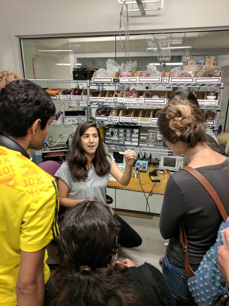
This week was one of my favorites. Making a custom electronics printed circuit board (PCB) in 5min! Below is Amanda giving us a rundown of the Electronics shop.
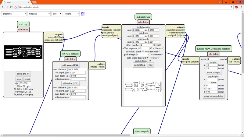
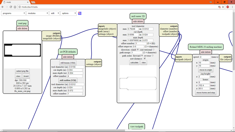
One important note was that you had to use a 1/64th bit and 4 offsets for the traces, and a 1/32nd bit and 1 offset for the outline (to cut out the board). Fortunately, mods.cba.mit.edu already had these default settings.
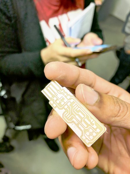
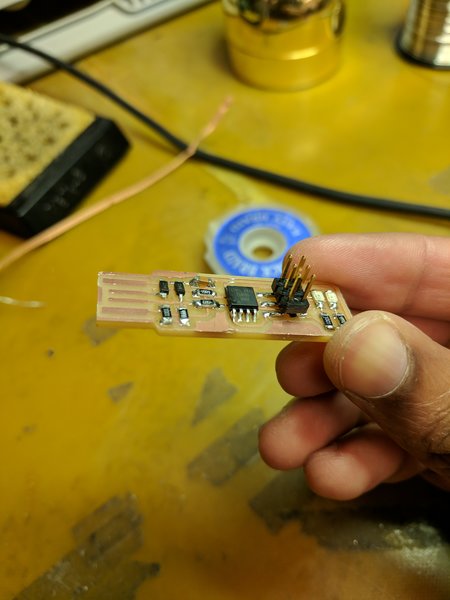
I milled, soldered, and created my own USB programmer (aka FabISP)! This week was all about following directions (link to tutorial).
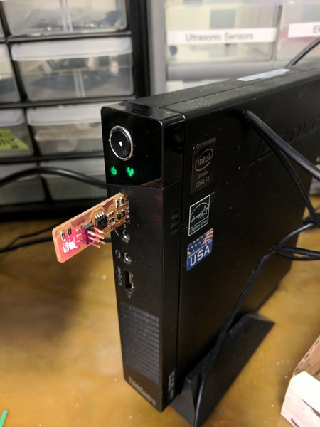
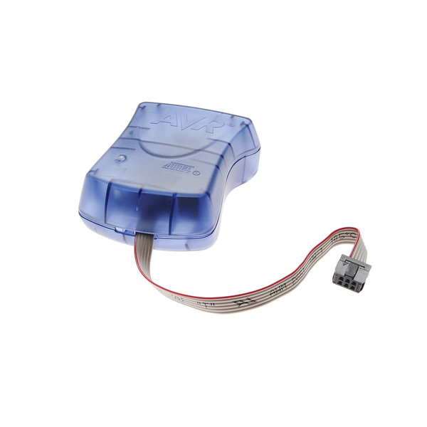
After connecting the fabISP to the computer I had to program it to be recognized as a USB. Make sure you download the firmware and connect the blue Microchip Atavrisp2 programmer to your fabISP (this is what programs your board to be a programmer). The detailed directions are specified in the above link.
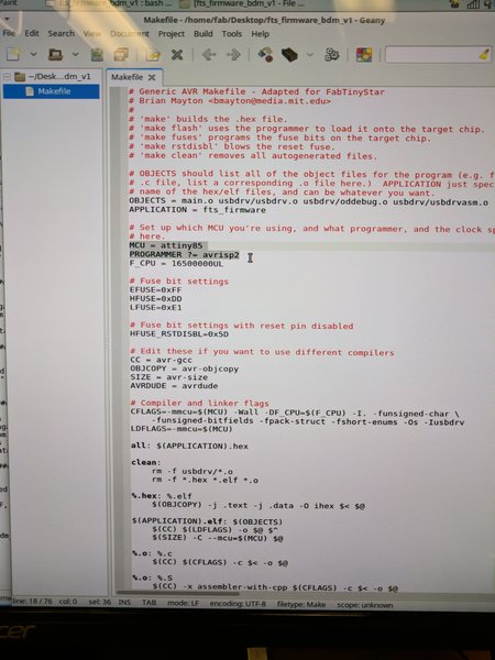
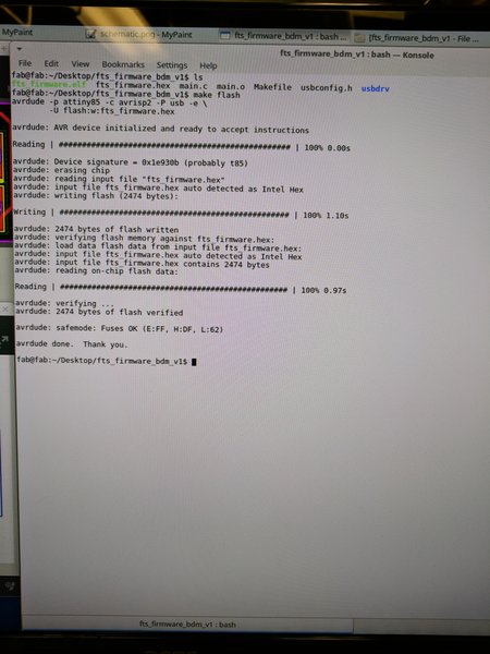
Configure the MakeFile to with your chip name (attiny85) and the programmer name (avrisp2). Then run "make" in the command line, assuming you're in the right directory.
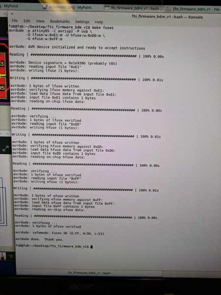
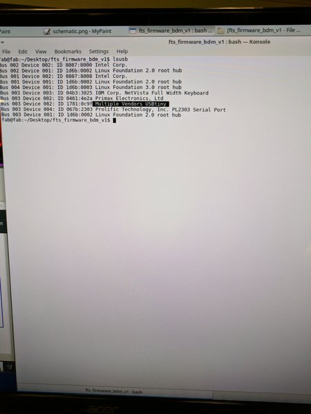
Finally, run "Make Flash," "Make Fuses," and "lsusb" in the following order and you should see your USB configured!
Special thanks and credit to Brian and his amazing tutorial. Also, I recommend Linux for this week's project, so just use the lab computer unless you have a Mac or Unix station.