This is a cool week. I learned how to use Eagle circuit design software and designed a new PCB with an Atmel ATTINY44 chip, button, and led interface.
Eagle takes 5-6 hours (or more) to learn. First, go through the How to Setup and Install Eagle tutorial.
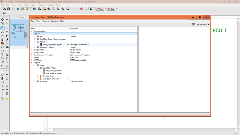
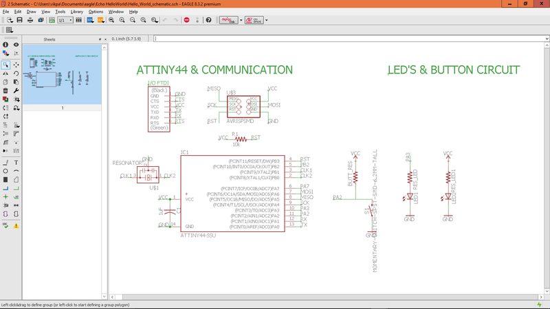
Then go through the Part I and Part II of designing a schematic and board layout for your first circuit. REMEMBER to add the Atmel-Eagle Library so you can incoporate the ATTINY microcontrollers. The Sparkfun library doesn't have these.
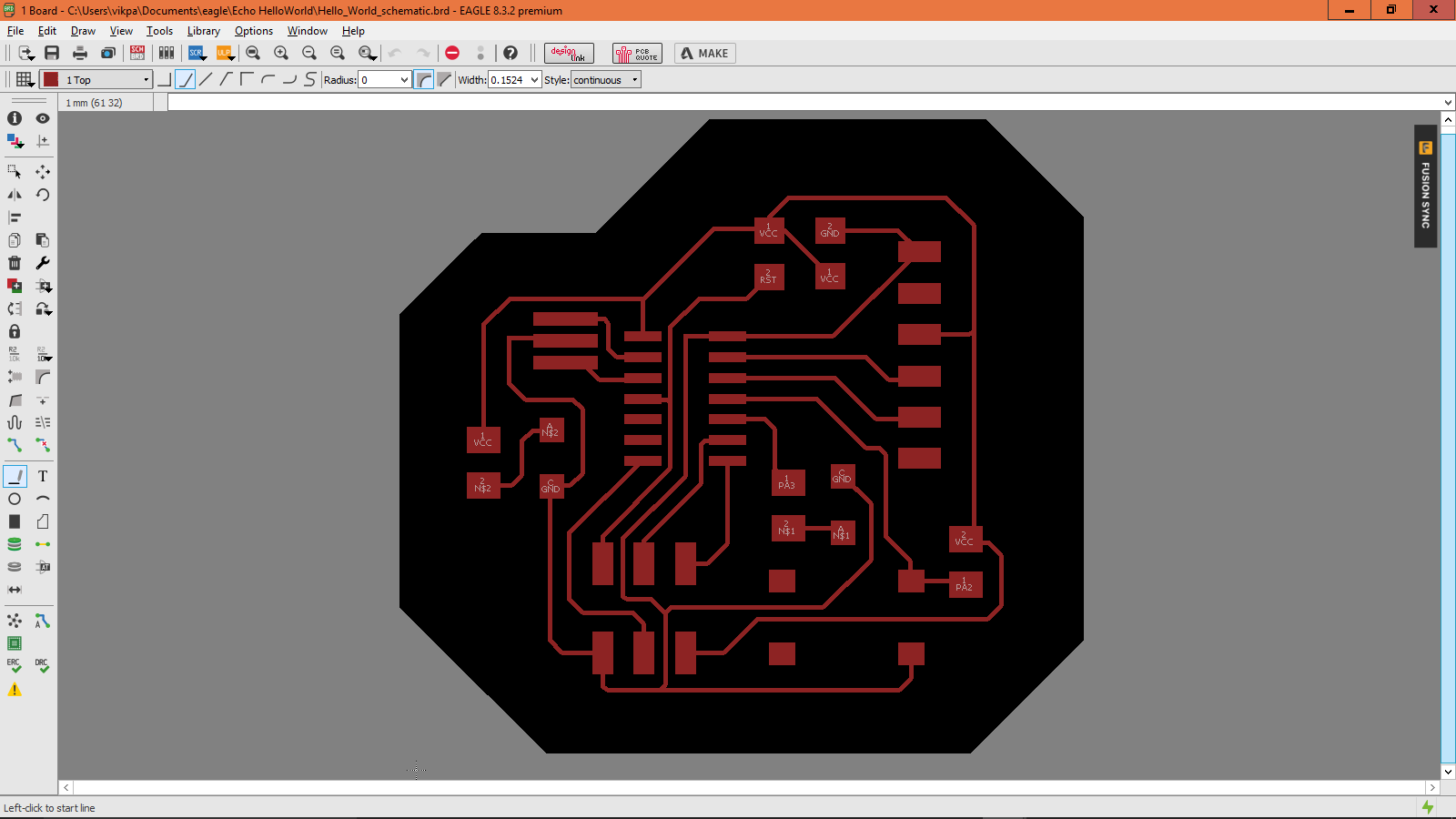
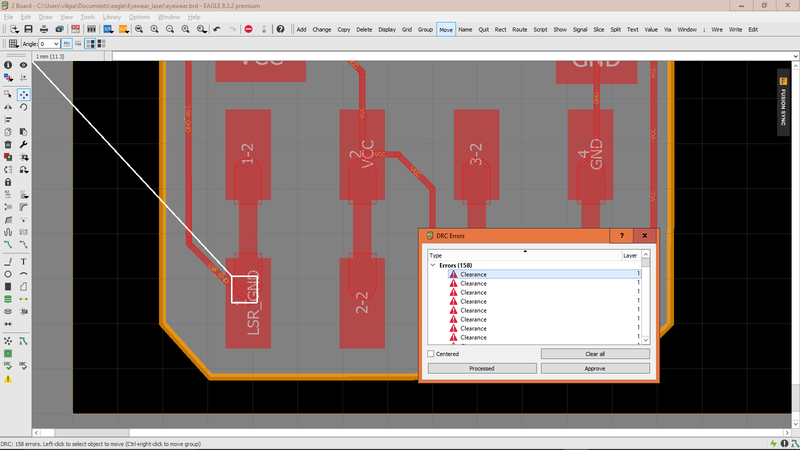
One mistake I made when routing was making my routes too thin. I recommend 0.254mm or larger. As a result of the mistake on my first board, I had 158 DRC errors. You only need to run DRC on the top/copper layer (for a one-layer board of course).
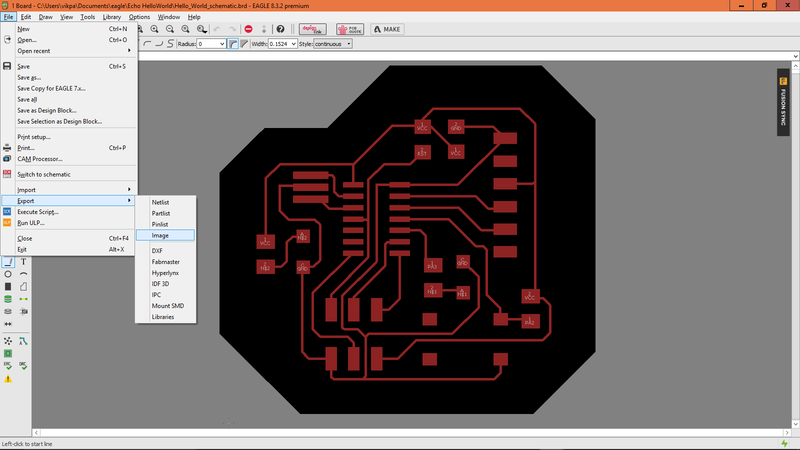
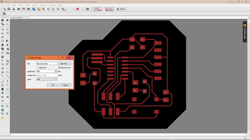
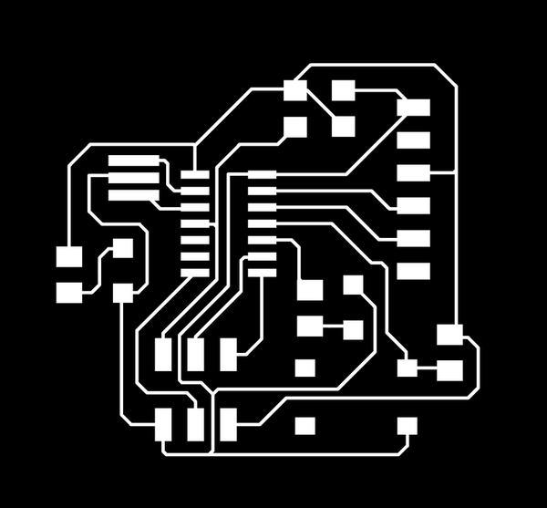
When you are ready for milling, you have to export the Top layer and Boundary layer as monochrome PNGs with 999dpi. This is what you will send to the milling machine to make your pcb.
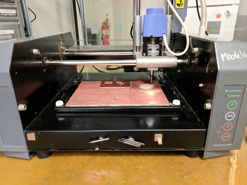
Now time to mill! Refer to class notes or my week03 electronics post to remember how to mill.

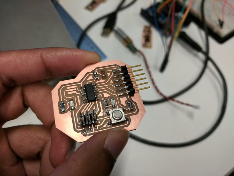
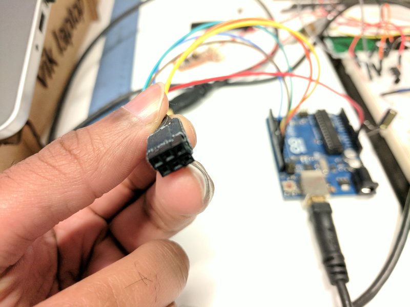
Then solder your board with the correct components and program it via the FabISP we made from week03 or the Arduino! I programmed my circuit to turn an LED on and off when you toggle the button.
Special thanks and credit to Thras, our CBA TA, for helping us get started on Eagle.