 Source: Mashable.
Source: The Machines, Directive Games.
Source: Mashable.
Source: The Machines, Directive Games.
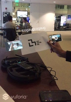
What if you could have your own holographic glasses that enabled augmented reality experiences as shown below (which unfortunately are just limited for smartphones)? Here's my attempt :)
Source: Mashable.
Source: The Machines, Directive Games.
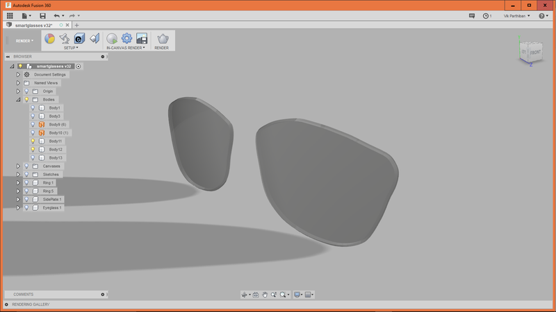
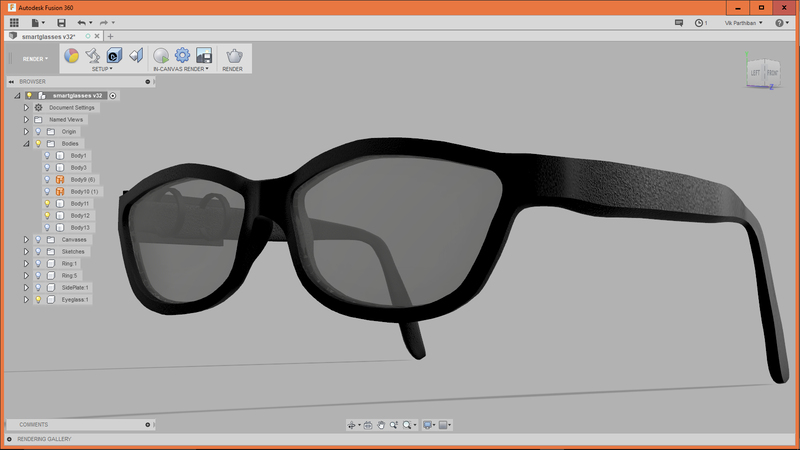
Designing the Eyewear in Fusion 360. I brought in 2D sketches into Fusion and then used the Sculpt mode to model in 3D (see Week 1).
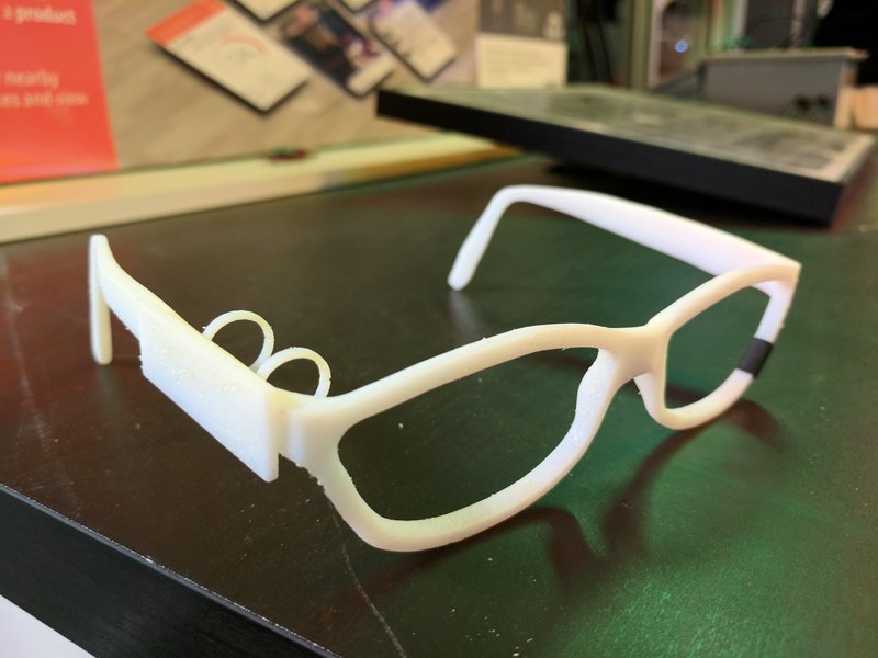
3D printing test design.
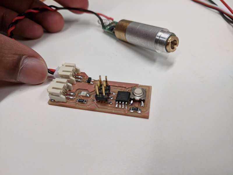
In order to see holographic video for the optical display you first need a laser (currently just doing green). Here's my circuit below! It consists of an ATTiny45, BJT, and button to toggle the laser (see Week 7).
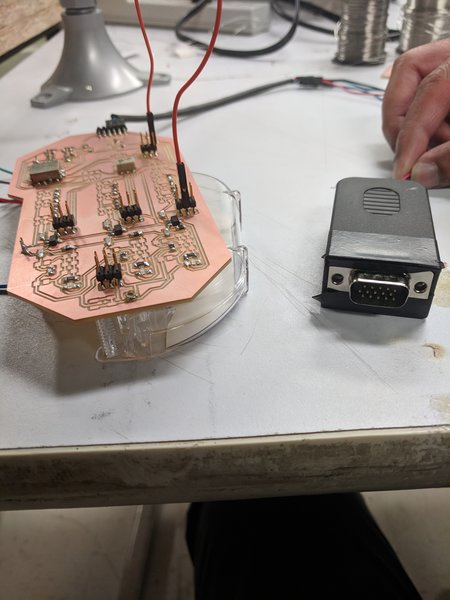
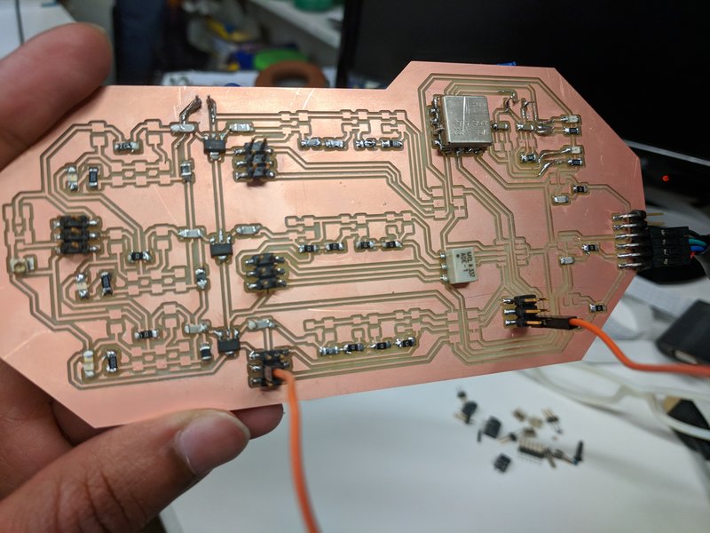
RF electronics is used to convert a standard VGA output from a computer to a readable format for our optical lens (which takes 30dBm at 400Mhz). The process is as follows: carrier generation, analog mixing, and power amplification.
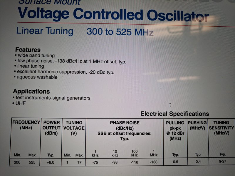
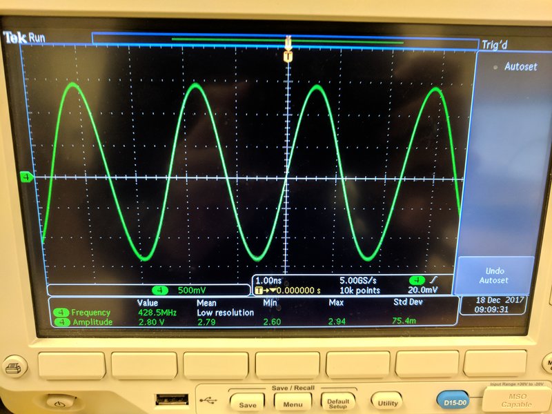
You start with something called a Voltage-Controlled Oscillator (VCO) to generate a sine wave (aka carrier wave).
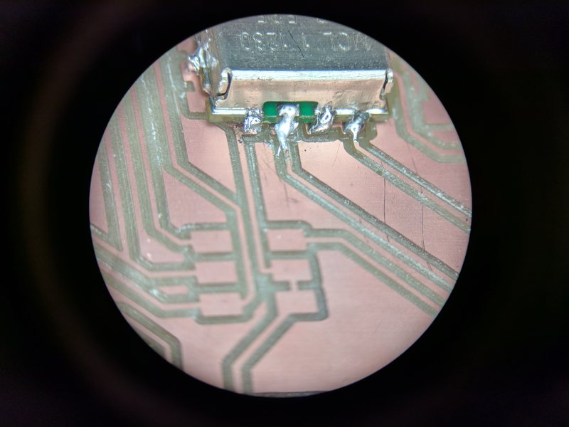
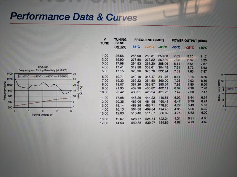
I was using a ROS-535 VCO which allows you to create a sine wave between 300 and 525 Mhz. Our display takes needs about 400Mhz, so I tuned the voltage using an onboard potentiometer to about 9volts per datasheet.
As you can see, this VCO needs two Voltage supplies, Vcc (12V) and Vtune (in this case 9v), to function. Check out the cool sine wave though!
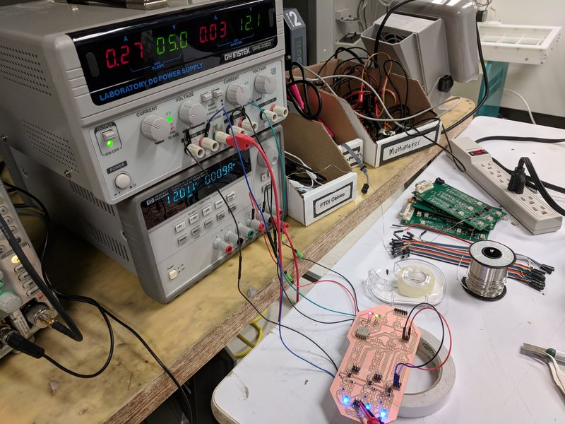
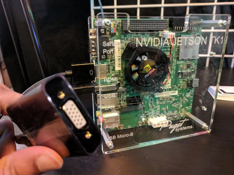
Next I connected my VGA port from a portable computer (Nvidia Jetson TK1) to the RF board. I just broke it out into Red, Green, Blue, and Ground pins via some headers.
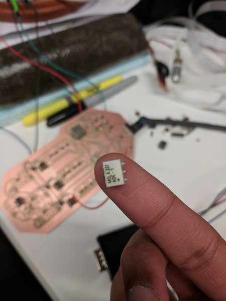
Then, you need a Mixer (ADE-1) which modulates the analog data channels from the VGA port with the VCO carrier wave to send to the display.
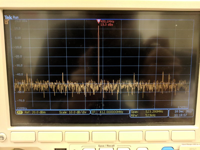
Lastly you need to amplify the wave to 30dBm which is the input power required for the display. You do this by adding Operational Amplifiers. I used a GVA-60 which requires 5V, and I was able to squeeze out 13.3 dBm so I still need to cascade more op-amps.
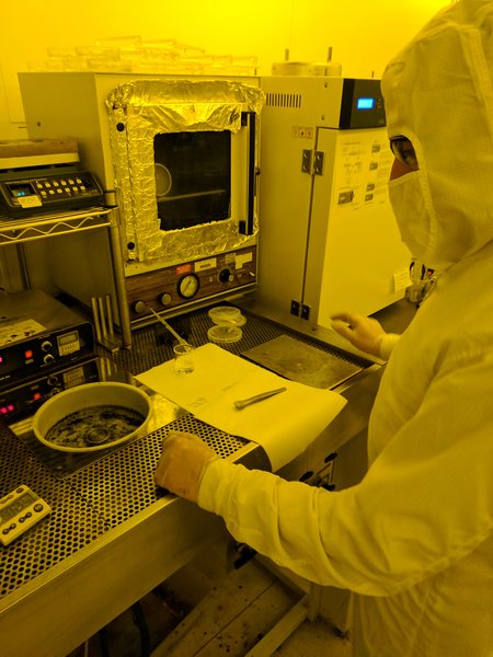
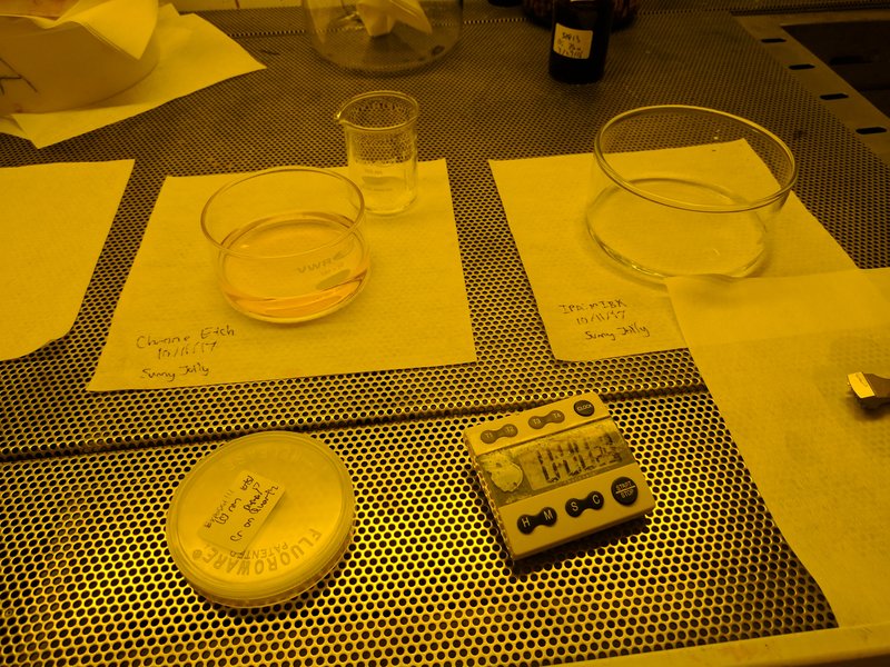
Sunny Jolly showing me how to spin-coat resist for optical eyepiece. Also need to evaporate 10nm Chrome layer on top to avoid charging on Ebeam(not shown).
Write test nanostructure grating using Elonix, MIT's Ebeam lithography system (basically a $5 million nanoprinter).
Next step is dissolve Chrome layer with Chrome Etch (Acid) and develop in 3 to 1 IPA:MIBK (Solvent)
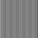
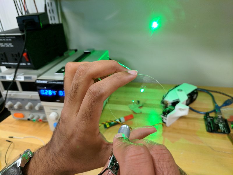
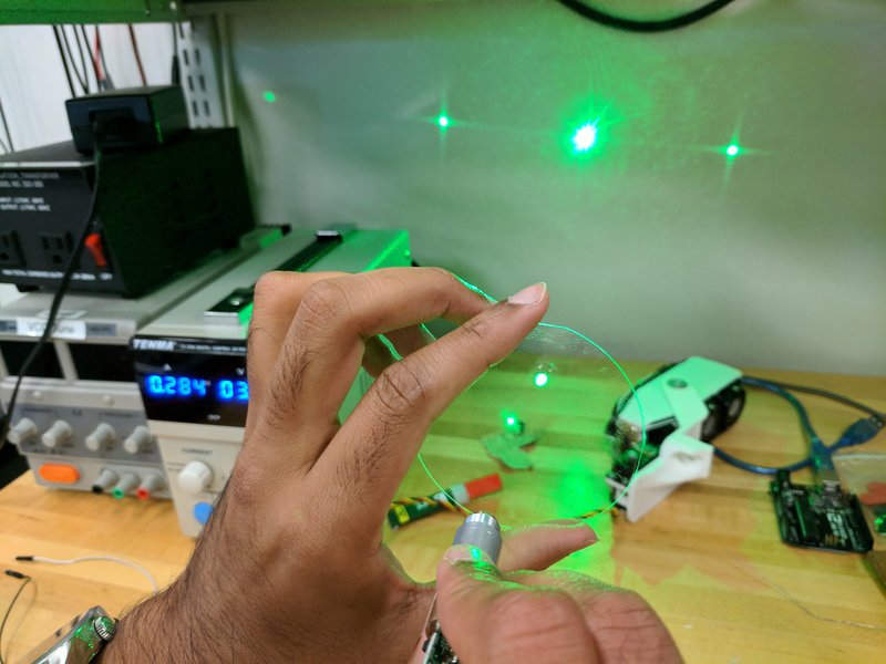
Test Diffraction Grating
Write more complex nanostructure (greyscale phase pattern). Thanks again Sunny for your help!

On Elionix, program each greyscale layer to get a different dosage, which gives phase profile.
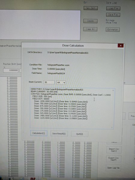
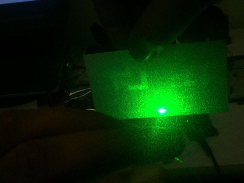
And the hologram worked!! There is lot of zero-order light and speckle. Next step would be to connect the VGA-to-RF Analog board to this lens and edit the nanostructures to see holographic video (will require some wire-bonding).
One thing I haven't mentioned is how you compute holographic data in real-time at gigapixels per second. Well, having a GPU is a plus but the problem is computing Fourier transforms of 3D point clounds at high frame rates. My display operates on these fourier responses, so we need to find an optimized solution to the computation (maybe tensorflow?). Secondly, the optics for my display is not complete. In order to view the display information as augmented reality content, I need to add some Bragg gratings and metal transducers (which will probably be the topic of my research).
Special thanks to CBA, MTL, and OBMG research group for helping this idea come to life! If you're curious about my work at the MIT Media Lab, feel free to email me at vparth@mit.edu.