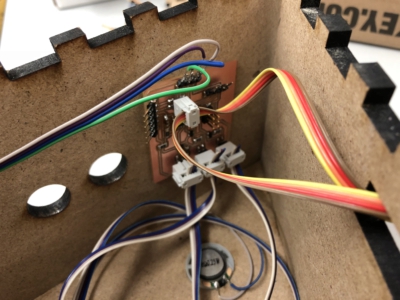
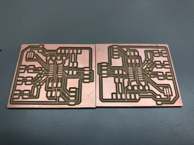
There were three main errors that I made during the design and construction of the boards: 1 First I added a 5V regulator that was present in Neils board but realized that if powering through FTDI this is not only unecessary but if the topology of the board was similar to my first design (not shown) it actually caused a competition between VCC from my computer and the 5V regulator. The next critical error that I made was that I put resistors in from of my N-MOSFETS (aka between the pins on the atTiny and the MOSFET. This had no effect on the current going through the speaker so I continued to burn out speakers. Eventually I figured out that I needed to change the placement of the resistors and ended up getting reasonable amount of current through my speakers. I first tested the individual capabilities of the board.
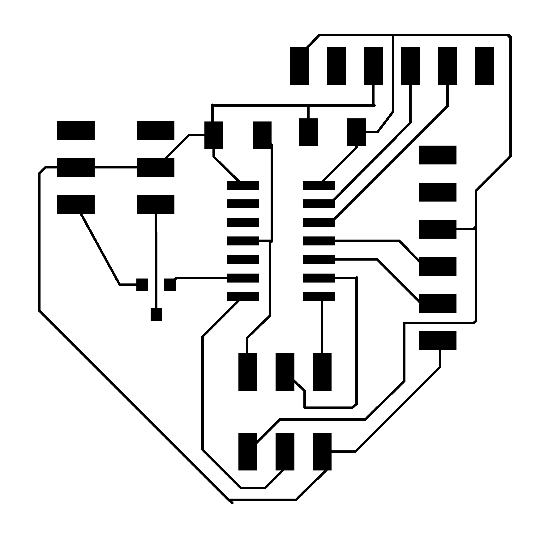
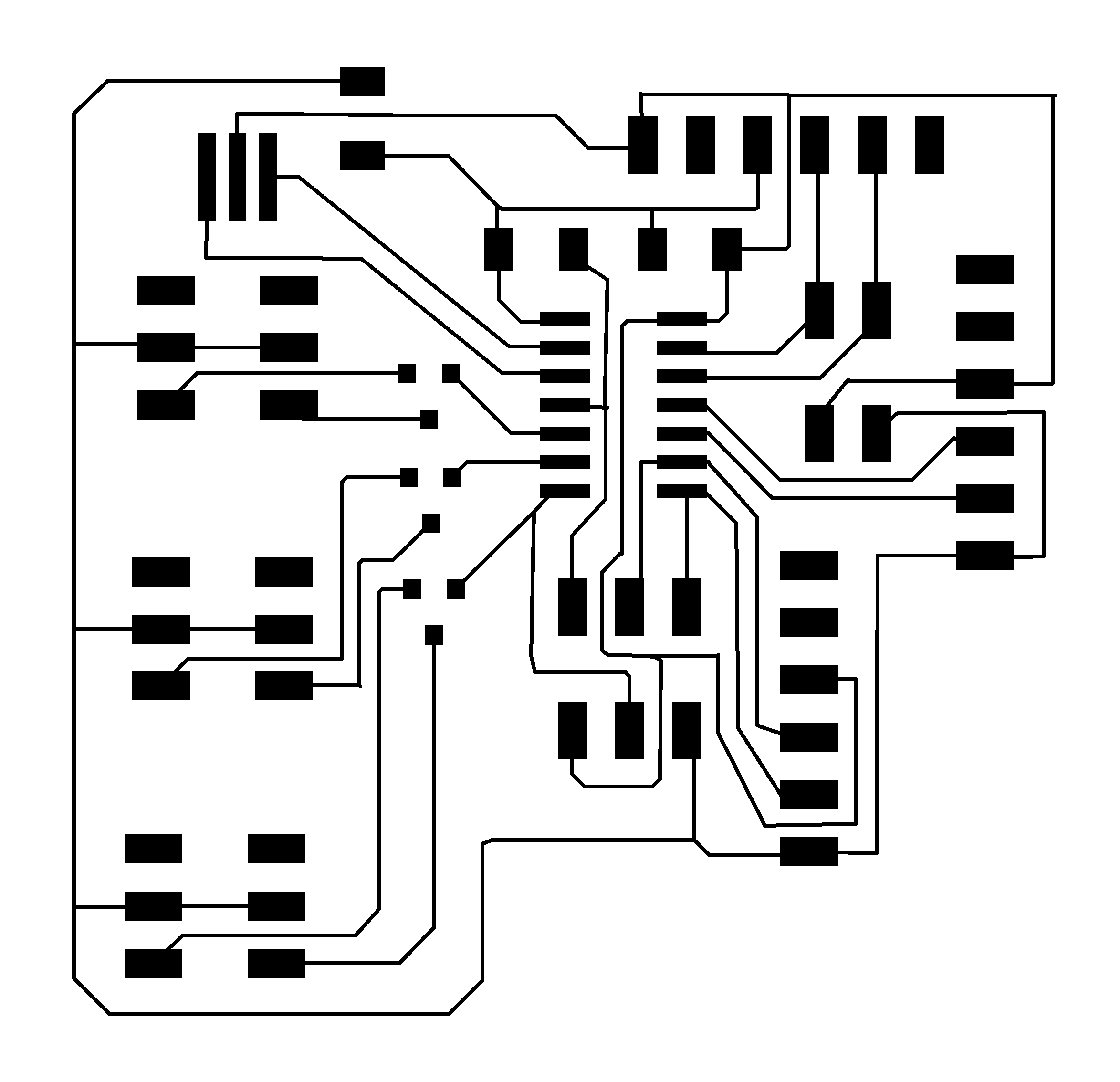
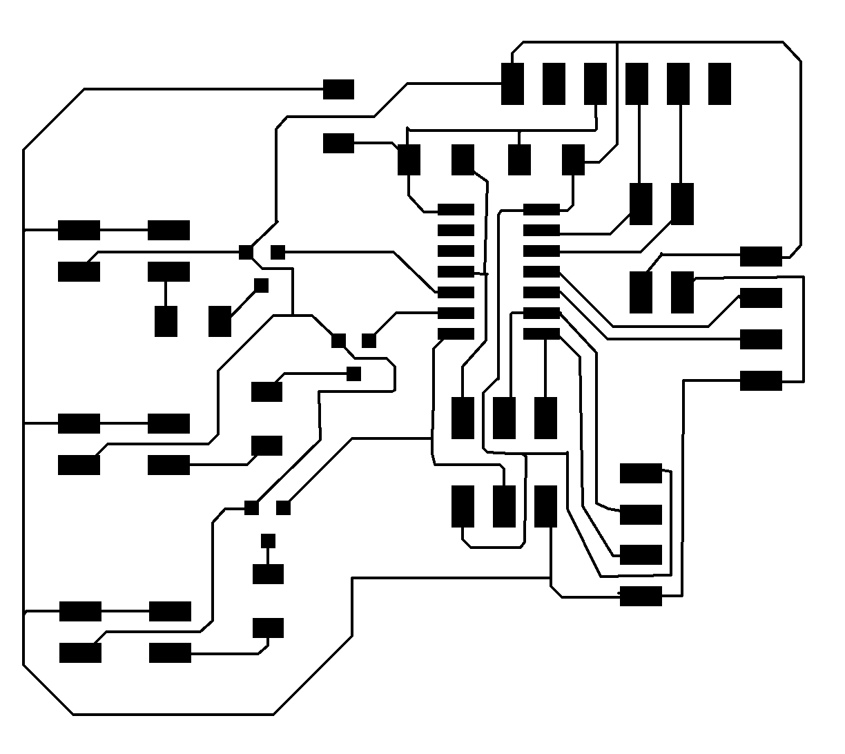
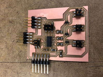

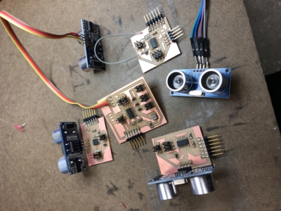
First I programmed the board to perform an echo hello world through the serial port and confirmed that I could send and receive messages. Next I programmed the board to play a mellody by performing software/bit banging PWM. This was relatively easy to implement although I first tried to use built in functions in the Arduino library before realizing that this was not going to work. Below you can see a video from my input week translating the range sensor input to the tempo a melody.
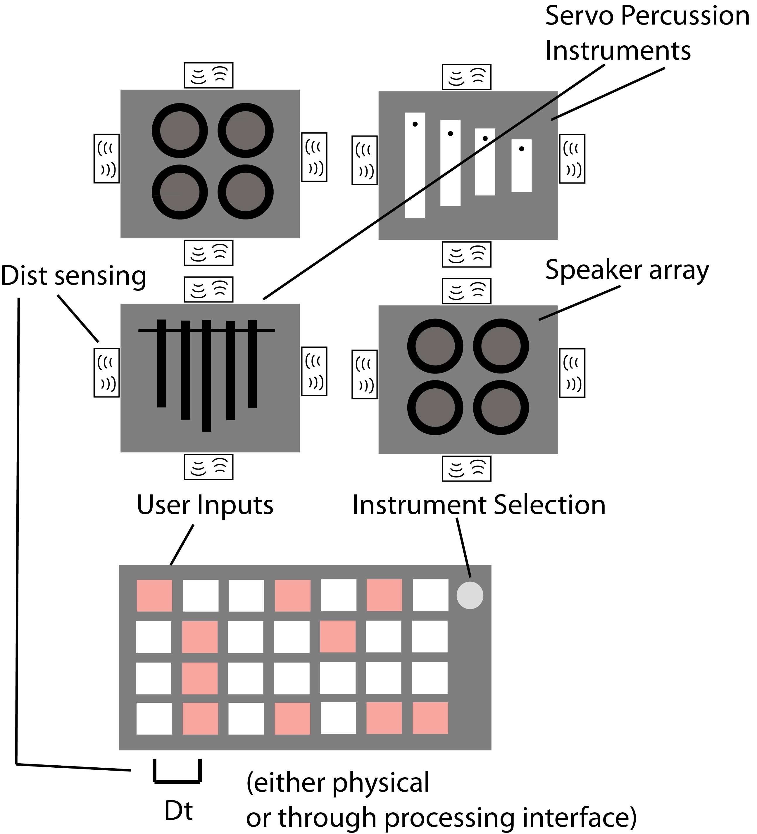
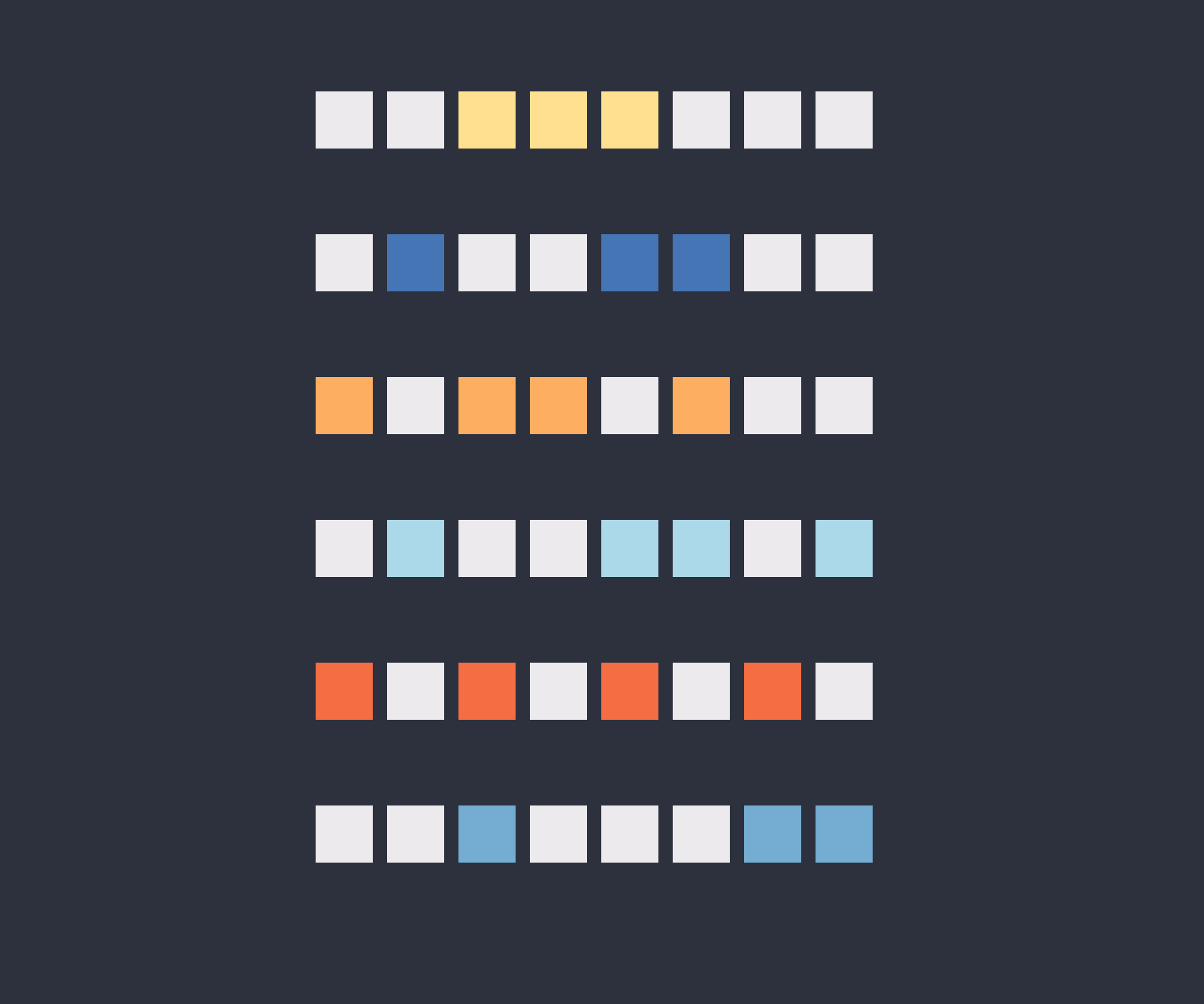
Next I used a tutorial found here https://learn.sparkfun.com/tutorials/connecting-arduino-to-processing, to learn how to properly set up a serial connection between processing and Arduino. In my applications programming week I had streamed hall sensor data to processing to make a visualization of the proximity of a magnet but I had not been able to receive data on my microcontroler as well. It was extremely exciting to get my melody to play on a click as shown in the second video below. This essentially replicated the tutorial. The next part which was much harder and even more exciting is demoed in the final video in this set. I wanted to let specify the times at which the speakers should be active. So I first made a clickable grid of buttons and tried to send the button states to Arduino which would then decode the buttons states and execute a mapping from buttons to tones. My first error was that I tried to send a string and then translate that string into an integer array value in Arduino. This was very difficult to do for some reason. My main take away from both processing and Arduino is that while it is easy to make fast progress with them, especially if you have little C and or Java programming experience, it quickly become difficult to debug since feature are hidden behind a thick wall of built in libraries etc. The solution that I opted to go with in the end is to send strings of ones and zeros which contained a header and tail character set which could Arduino could use to align the data (for example <10010101>). This was critical in the end because I could simply changes the head and tail characters for each node to ensure that each board only listened to a single line of the user interface buttons.
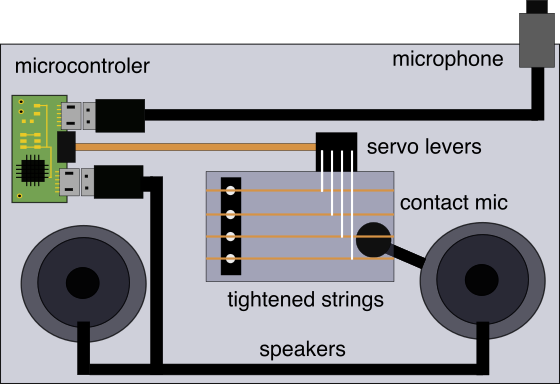
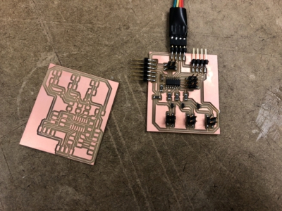
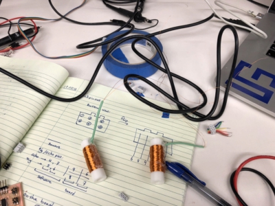
Week 9: Inspired by this tutorial Eghbal and I made a solenoid driver for actuating our
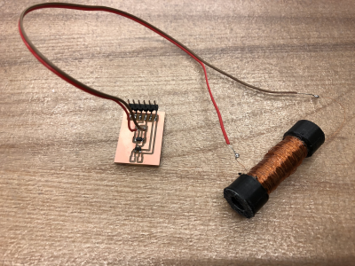
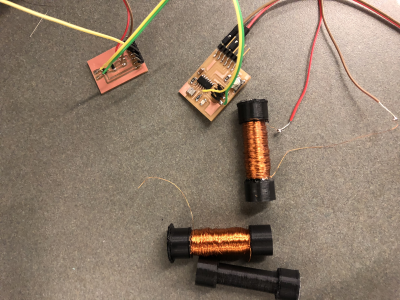
SOLENOIDS
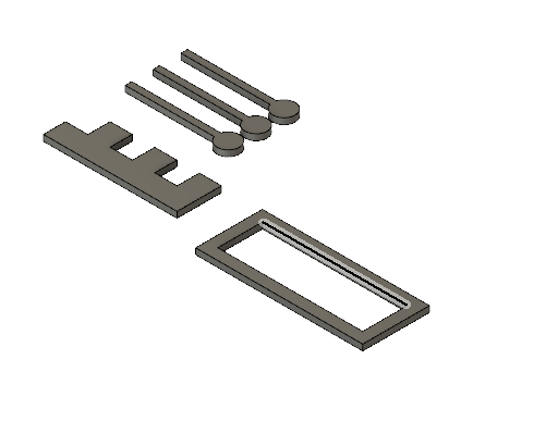
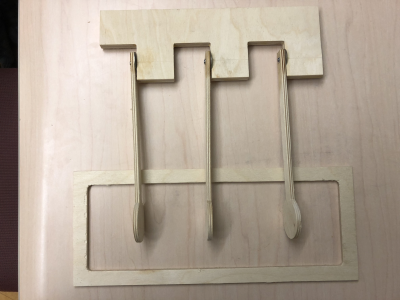
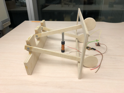
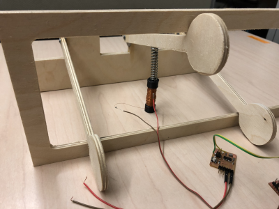
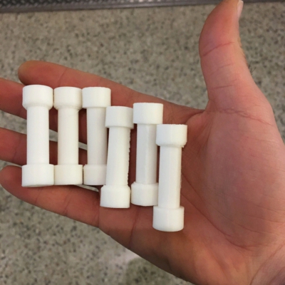
Actuating out mallet to strike the xylophone bars. I designed a 3D printed part that we wrapped together in the EDS shop (see output devices week). After wrapping several of these we designed a sister board for the echo_hello_world+button board and used the button to modulate the frequency that the solenoid was driven. In addition our first idea of an instrument was to use the solenoids to drive a wooden mallet, shown below. In the end this was much too bulky to move so we opted to strike the bars directly with a solenoid driven piece of metal

ALUMINIUM
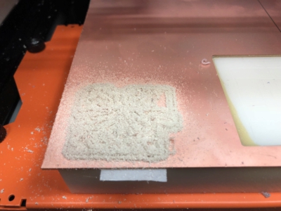
W8: Wanted to cast aluminum bars for a mini glockenspiel set that could be played by servos. With an attachment. Not sure if this is the best way to do it or if I should cut aluminum bars. Todo: fix where holes are so that they coincide with nodal points.
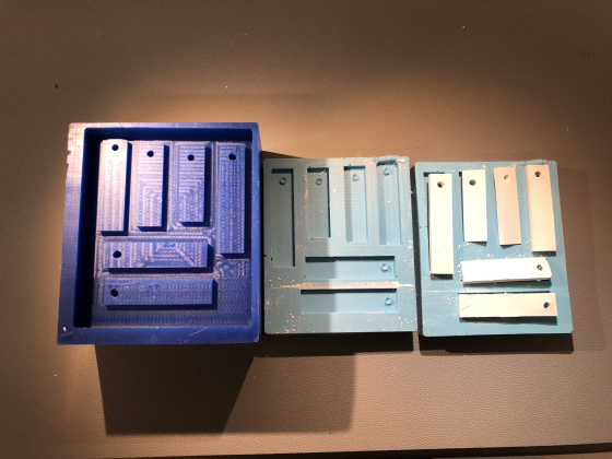
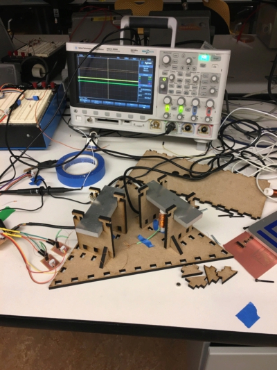
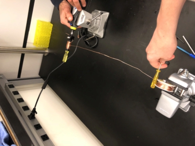
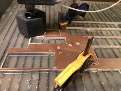
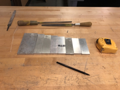
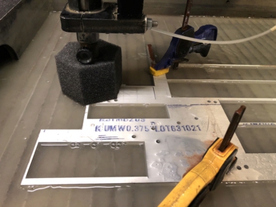
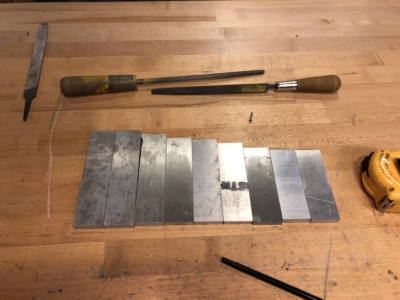
Our friend from Ed Boydens lab was nice enough to help us cut a series of aluminum bars using scrap aluminum that we found in the BCS department that was left over from custom microscope construction (this leaves some uncertainty in the cost of the parts but I think that aluminum is somewhat standard). We used the water-jet cutter with garnet in the CBA-shop to cut out a series of bars using the dimensions specified in the tutorial linked above. In the end the bars actually sounded great although if you look at the second photo you can see that near the end of the cutting process the material began to oscillate leaving a series of large imperfections in this bar which severely damped the bar. Afterwards we deburred the bars and used a metal file to soften the edges.
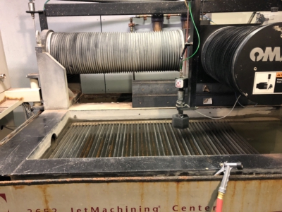

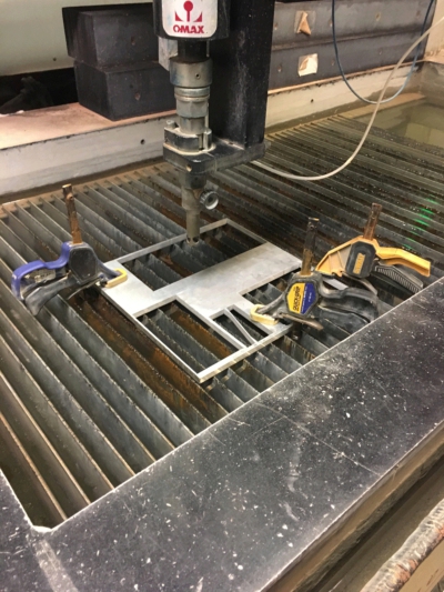


Here you can see us aircutting one bar before cutting.
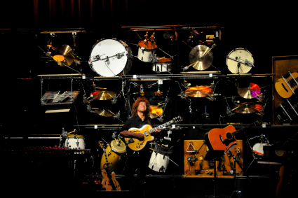
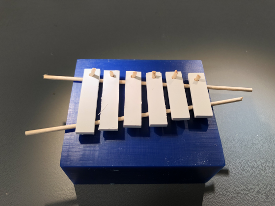
They sound great and the Solenoids work!
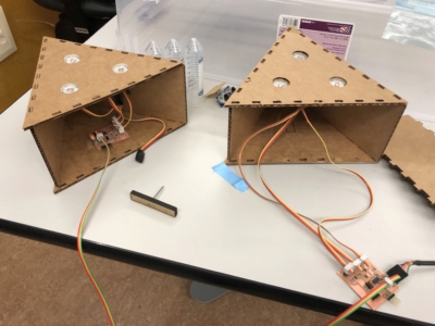
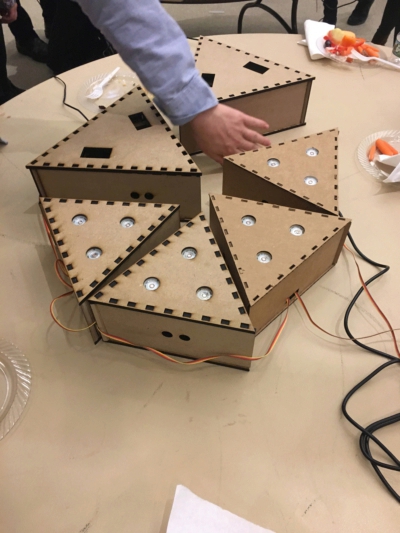
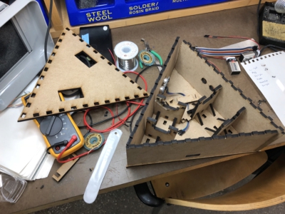
HOUSING
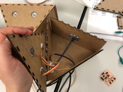
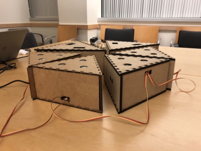
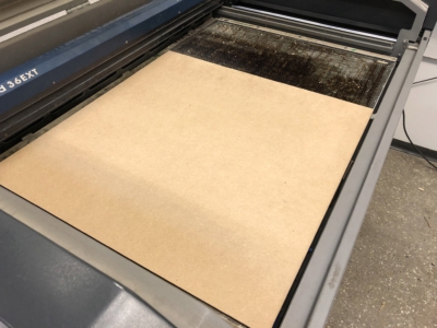
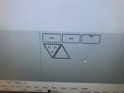
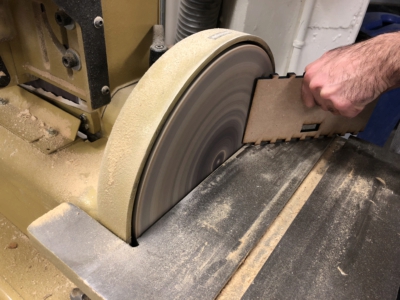
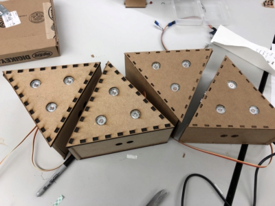
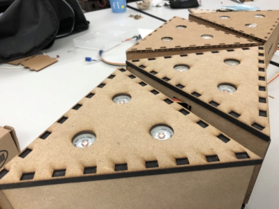
We designed to housing for our instruments to be laser cut either in cardboard or mdd which was actually surprisingly easy to cut and looked great (plus it was cheap… $5 for the board in the first image. The design was made in rhino and actually did not fit together perfectly. Eghbal fixed the design for the later boxes but to use all of the mdd that we had bought we used the belt sander to “fix” the edges manually so that the box could snap together. My boxes which only had speakers needed holes which could fit the speakers. Using the exact diameter of the speakers worked well because there was some give in both the cardboard and the mdf allowing the speakers to “pop” in. The housing for the bars had a pegboard at the bottom with a shelf that allows the bars to slide in which space for the solenoids underneath.
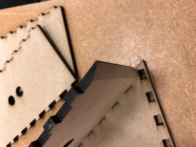
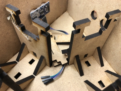
Assembling the boxes was relatively straight forward. We had to put a opening in one of the sides to allow the serial but cable to connect each of the different board which looked alright although connecting in the boards in this way was less elegant than using bluetooth etc. which we had considered early on. After assembling everything there was a fair amount of troubleshooting with the code and the boxes need to be disassembled several times to reprogram the boards. Once again Arduino and processing really allowed us to easily write and test code but made debugging very confusing. Declaring integer variable inside of one of my functions seemed to disrupt serial communication which was baffling while using chars caused no problems at all. In the end we opted to use several different header and tail characters for decoding the different nodes and used the distance measurements from the sonar to modulate delays within the loop which played back the “melody”, if I can call it that.