Things I learned
- How to make my own circuits
- How to debug a circuit!
- How to refer to a datasheet
- How to use the heat gun
- Get a workflow for eagle
- Programming a board when it has hardware problems
This is the week when everything went wrong.
I looked at some projects to decide how to make a temperature sensor. I want to make something that gets hot, and it seems important to be able to tell when something is too hot/hot enough so I can turn it off. Ultimately, I want to make a feedback loop and keep things at the correct temperatures.
There are two types of thermisters, NTCs and RTDs. For NTCs, the resistance decreases as temerature increases, and the opposite is true for RTDs. I decided to see what lab had available (NTDs) and went with those. From scanning through some past projects, I found Morgen Sullivan's remote temperature sensor, which seemed pretty similar to what I wanted. This would allow me to sense the temperature of my candles without putting the board directly next to the wax. So that's what I did! I also had an led to turn on when the temperature got past a certain level.
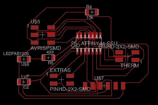
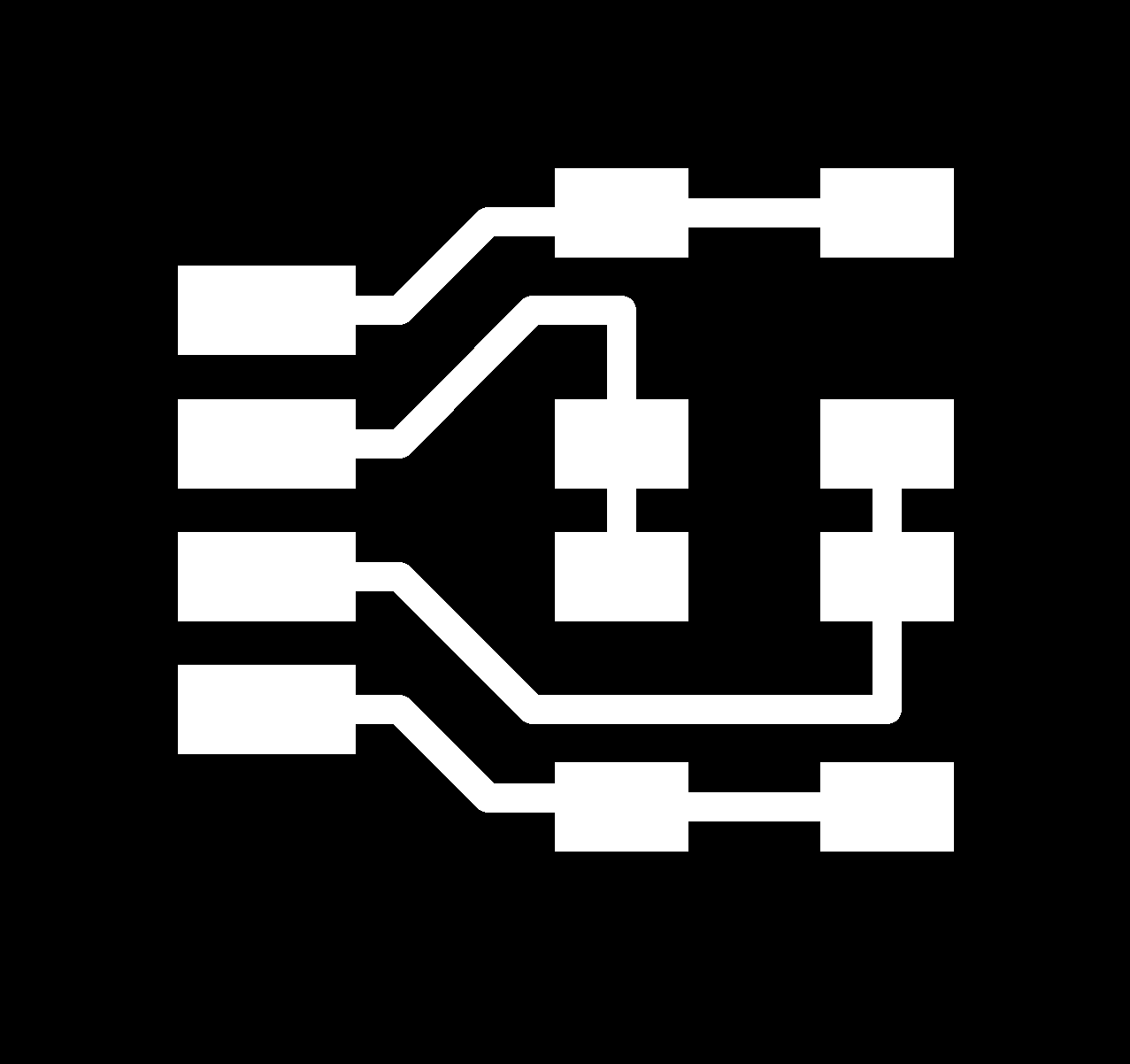
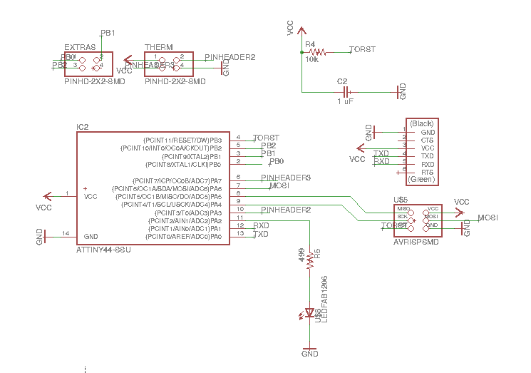 I didn't want to rely on his exact board, and I also wanted to be able to access extra pins. This is the first board that I made; it took a long time, but finally I had no airwires.
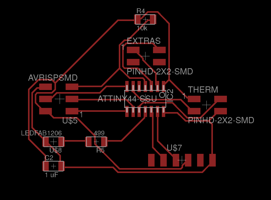
 Then I realized that the traces were way too thin. So I redid the entire board, and it was even harder this time because I couldn't go in-between components. I ended up giving autoroute a shot, and when the settings were right, the results weren't too bad. I fixed parts I didn't like (allowing for more allowance). Here's the second board:
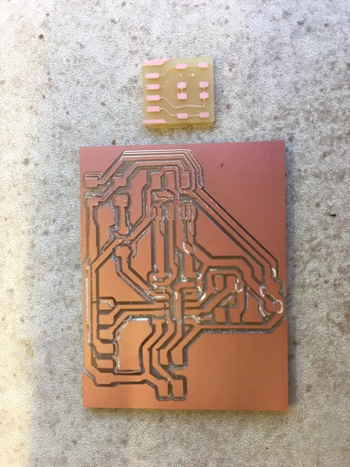 So I redid everything, and this time it was better. It took much longer than I was expecting though.
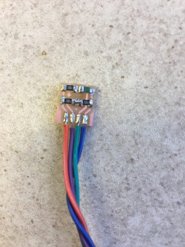
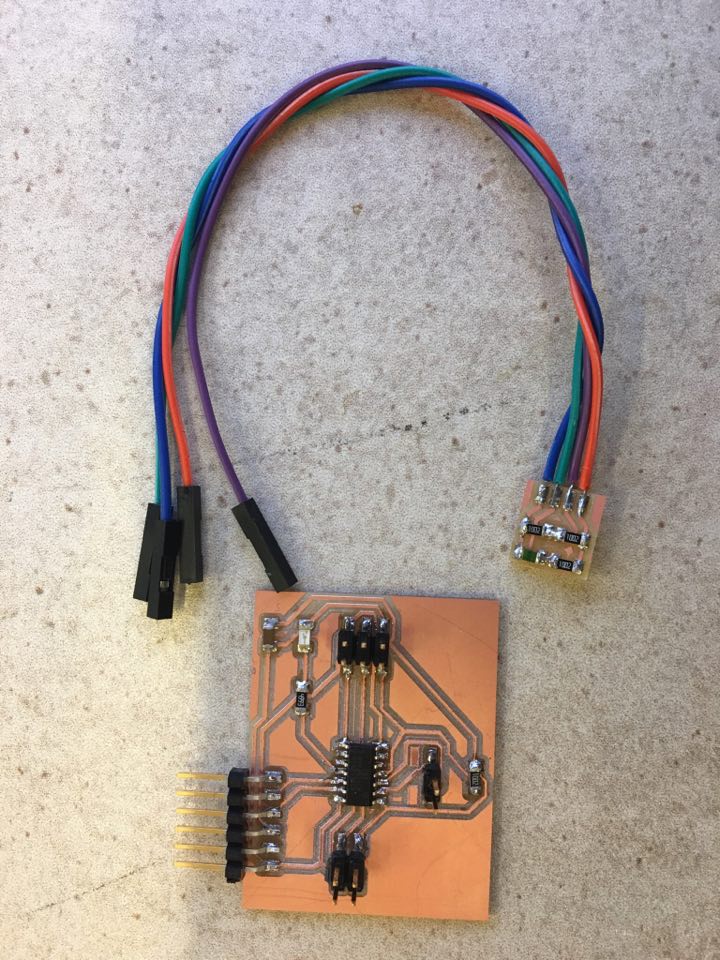
Soldering went fine initially. It was the same as doing the other boards. I made sure to correctly attach the main board to the external sensor.
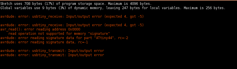
 Then I plugged it in to the FTDI and connected it to the programmer, but got an initialization error. That didn't work, and so I tred flipping th programmer cable. No luck. Then I flipped the FTDI. This was a really bad idea, because everything got really hot (and I have a burn scar to prove it!). The program still didn't work, even when I flipped the cable back.
By this point I had gotten my echo board to work with the Blink program (week 7), but when I tried out the same board with the same program again, it didn't work and I didn't know why. I kept getting an initialization error. I tried troubleshooting, but nothing worked. Then my laptop died. I plugged it back in and rebooted Arduino. This time when I plugged in the FTDI, the preloaded program from before made the board blink, but the program wouldn't reupload. So I'm speculating that maybe restarting Arduino fixed a connection problem with the FTDI, but nothing was fixing the programmer.
Then I thought that maybe I burned out both my thermister board and my programmer when they got hot. So I tried a lab programmer unit with my thermister board, but code still failed to initialize. Then I tried the lab programmer with my echo led board, and it uploaded but didn't blink - until I unplugged the programmer. Ben says that the programmer was probably holding down the reset pin. So there was definitely a problem with my programmer, AND with my thermister board
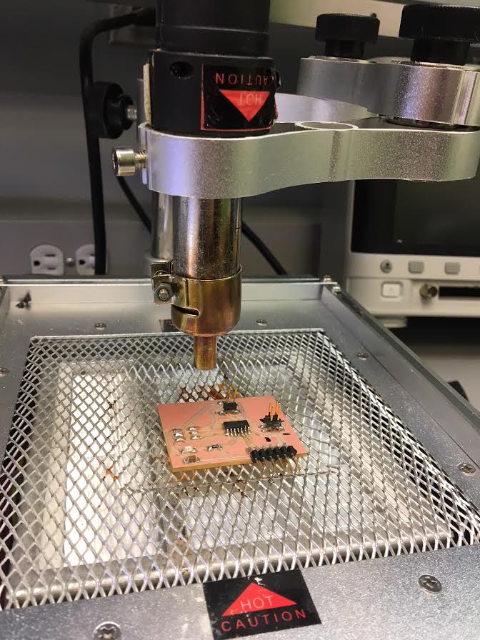
I decided to replace the atTiny on both boards. I used this crazy contraption to heat the board (with a focus on the microcontroller), then removed the boards.
 After resoldering on the atTiny for both, I follow the same process to figure out if the boards worked, but they didn't :(.
My new tiny was not soldered properly, so I fixed that. Blink was not working on the thermister board (with the new pin number); in a seperate program, Serial was not working either. Ugh
On a later day, I talked to Gavin about these problems, and he said my LED wasn't working because it was no longer a PWM pin.
Then I decided to try out SoftwareSerial to read the NTC values. I had some issues, but eventually, the port started spitting out some gibberish. Nothings worked. Gavin said it might be something with baud rate, but I tried all of them and still no luck.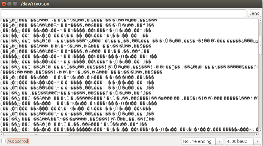 As a desperate attempt, I tried switching the clock rate to 1 MHz, and for some reason, this worked!