The Process + Pics
- Learning the material
- The Boards
- Revisiting past weeks and SoftwareSerial
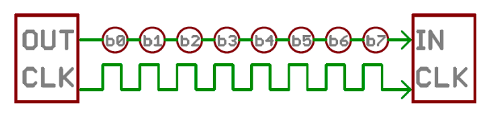
Most of my work for this week was just learning how Serial Communication actually works. I started by learning about parallel vs. serial. I knew the concept vaguely, but didn't know that serial is so common because it helps save input/output pins. This makes sense, because when while designing boards, I've been having to take this into consideration. I also learned how a clock is essential in making sure each bit is read correctly.
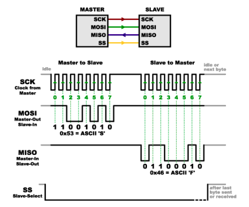
I wasn't sure if I would need a different protocol though, and also started learning about Serial Peripheral Interface (SPI). For this, I also read up a little bit about shift registers - in the future, I want to experiment with these more. For SPI, I learned how to wire up two boards with SCK, MOSI, and MISO. The concept of sending a listening command before listening is confusing, but pretty cool. I also learned about slave select; this would be useful for future circuits as well.
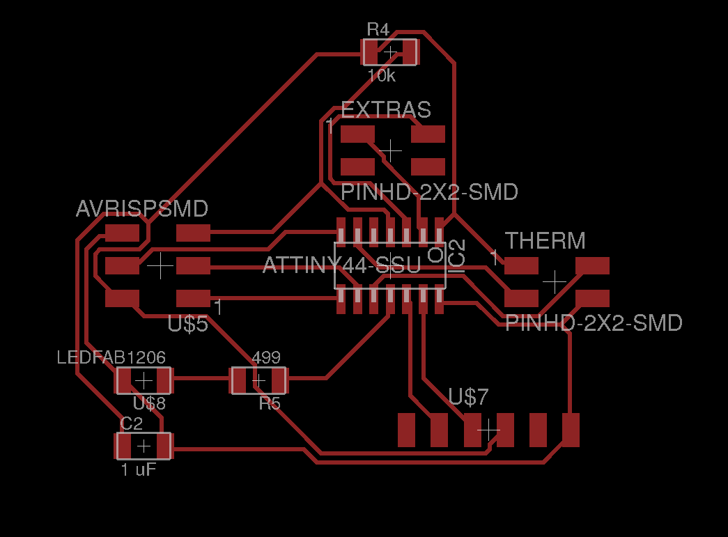
I used Eagle to design my boards. I originally forgot that I needed to connect Voltage and ground between my boards. So I had two boards that only had two pins each for the Tx and Rx. Sigh. It was a dumb mistake, but one that I won't make again. However, because it was just voltage and ground, I decided I could just add some extra sketchy wires to the VCC and GND pins on my thermister, and on the mosfet board I was designing for my final project, remember to include the VCC and GND. Here's a picture of the two boards that each only had two pins for communication.
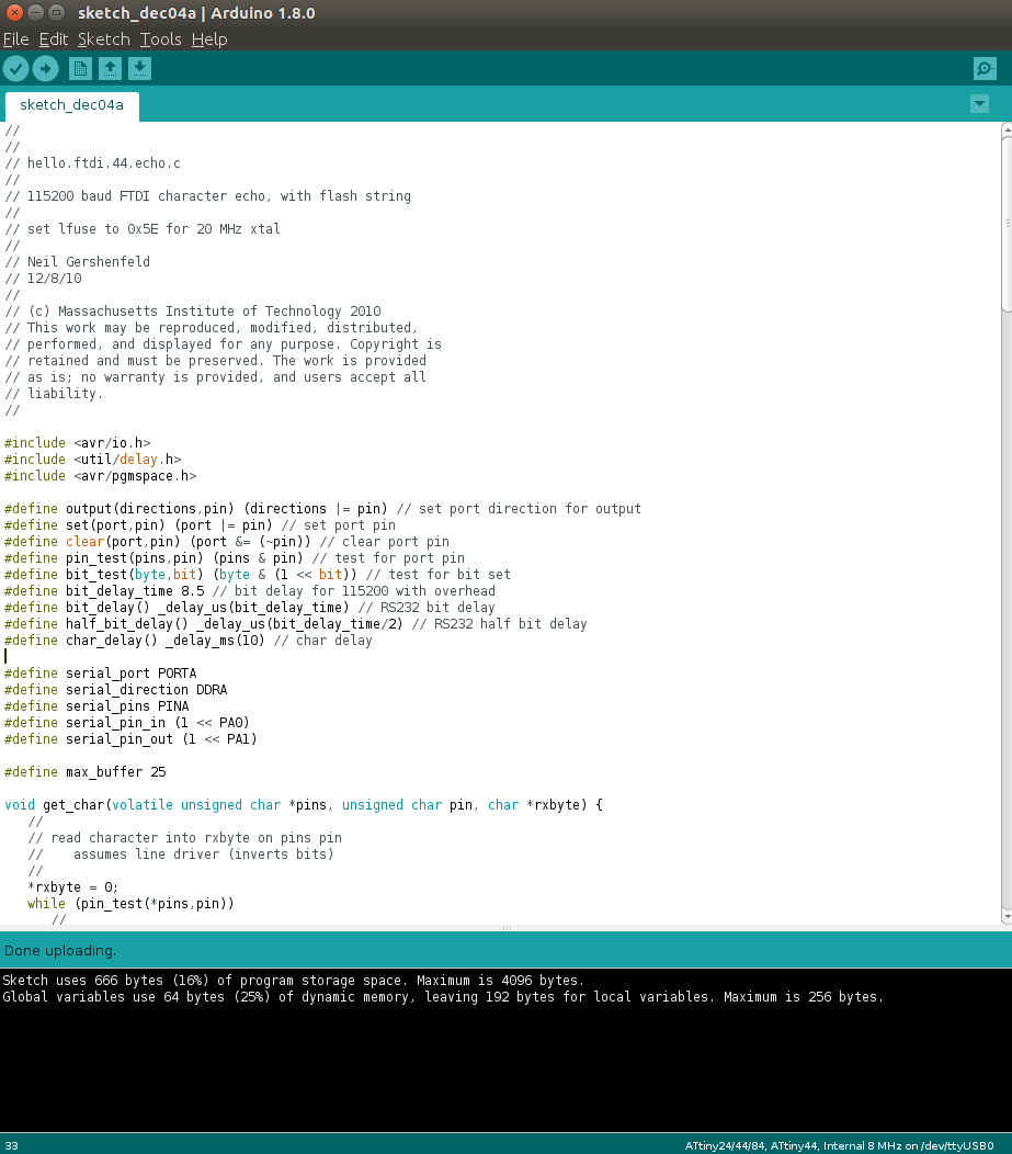
I didn't understand Serial before, but now I do, and it made Week 7's work with the hello echo make a lot more sense (code on left, forgot to screenshot actual serial port gibberish because I was so excited when it worked). So I decided to visit that again. And since I was behind and still finishing up the thermister stuff, I set the board with SoftwareSerial (read about it more in input devices) to read the NTC values in Serial (I'm so excited it worked after two and a half weeks!).