The Process + Pics there
- Creating the board
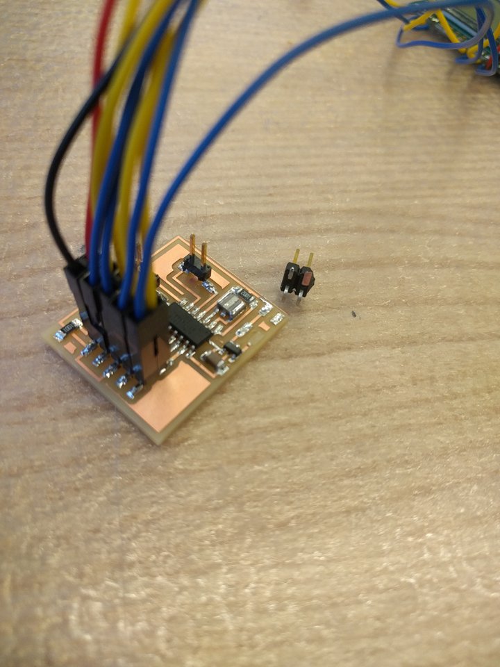
- Adding the components
- Debugging the circuit - part 2
I used a shortcut this week to design the board, because I wasn't sure if the LCD would work or not, and wanted to have more time for the code than to create the schematic. So, I used Neil's .png file and edited it using Pinta, an open source Microsoft-paint-esque software. The board was pretty much complete, but I wanted to extend traces from the unused pins so I could access them later if needed. To do this, I just added rectangles that represented a 2x1 pin header and the traces leading to them. The before and after are shown below.
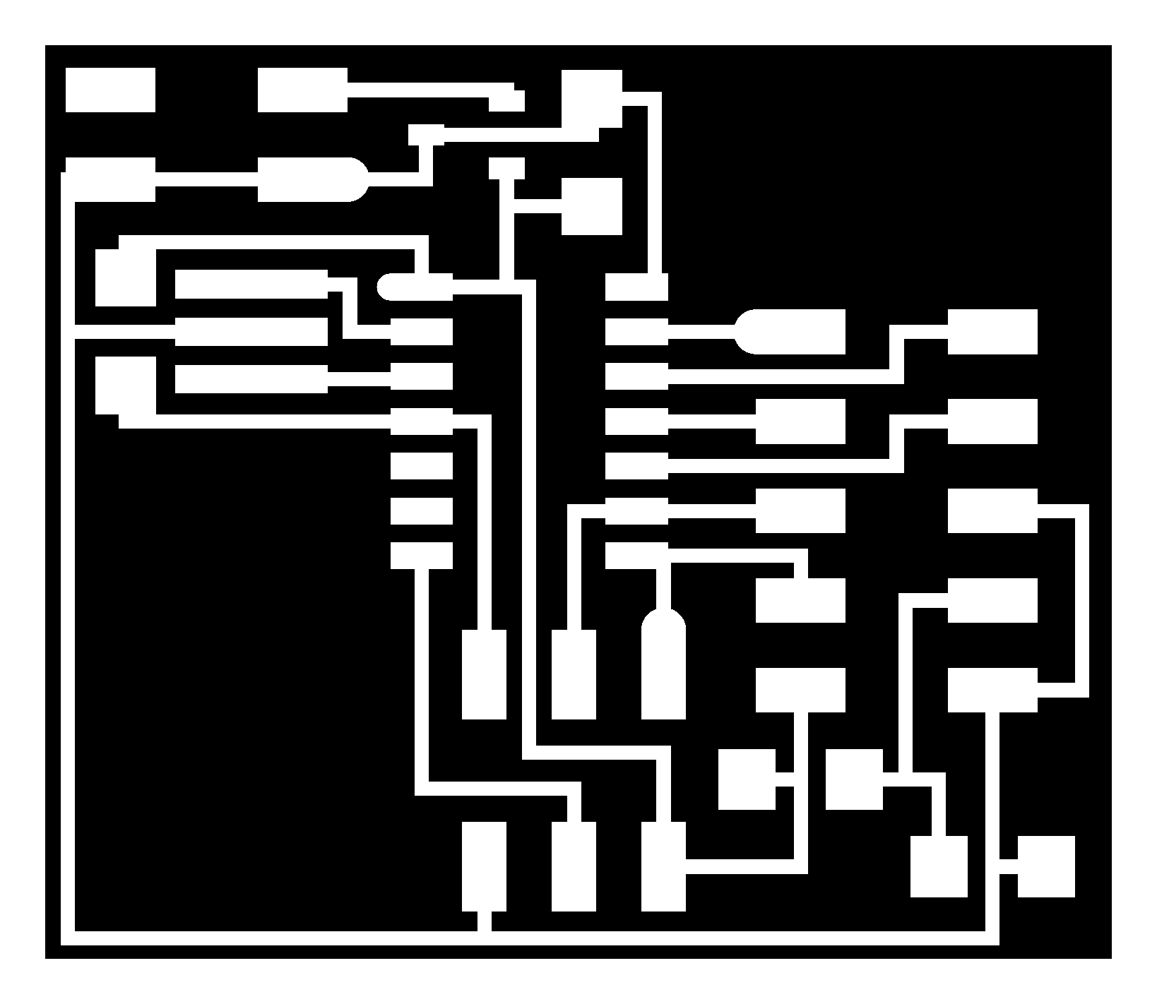
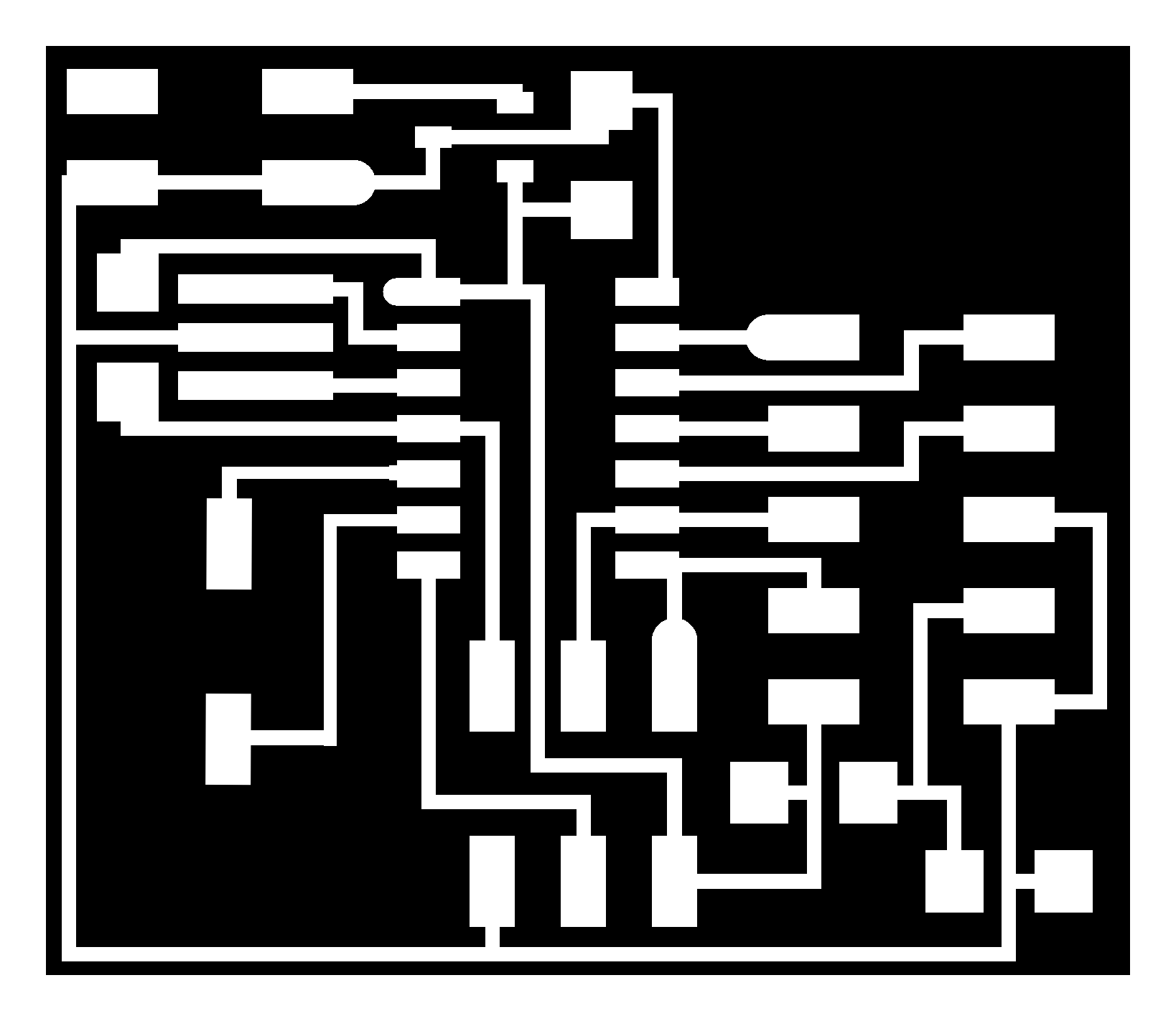
The mods calculated vector file seemed to look alright, so I went ahead and sent it to the milling machine.
Adding most of the components was pretty easy, but the voltage regulators that we had in lab had been *possibly* mixed up. So before adding it to my board, I had to do some testing. After consulting Gavin on the best way to do this (I've never used regulators before), I used a power supply to connect 7V to Vin and ground to ground on the regulator. Then I used a multimeter to check the voltages; ground and Vin gave 7V, as expected, and ground and Vout gave 5V, as desired! This was the correct regulator!
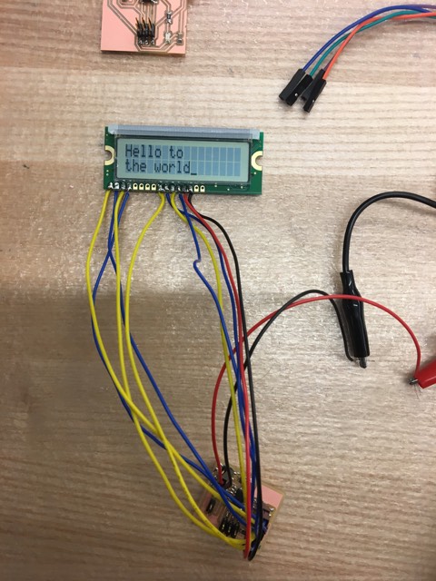
In addition, attaching the LCD screen required me figuring out the correct hookup. It took a bit of searching on the internet to find the correct pinout, but the pins ended up matching Neil's board exactly. Once I figured out the wires, I chose colors in this way: red for power, black for ground, blue for the other odd pins, yellow for the remaining even pins. I soldered the wires directly into the through-holes of the LCD, and left female connectors that can plug into the 5x2 pin header on my board. This makes it easier for me to attach the screen every time I need to use the board, but keep it separate to reduce the chance for breakage.
When I first connected the external power supply to my board, I wasn't careful and my pin-header was ripped out. The damage wasn't too severe, and I was able to get it back on (albeit, a little sketchily).
I was ready to program my board now, and I decided to test Neil's code before modifying it. I plugged in the external power supply, and then the programmer; the LCD displayed garbage only after the programmer was plugged in, and the area under the voltage regulator got really got. I tested all the connections in my circuit (using skills I learned during input devices), but everything seemed fine. Then I replaced the voltage regulator, just in case it had somehow gotten fried. Still had the same problem. Every time I plugged in my programmer, it got hot. Then a TA and I tested the power supply to circuit connection; we thought maybe the regulator needs a minimum voltage that it must regulate. So intead of 5V, we tried 7V. In this process, we found out that one of the jumper cables from the power supply box to my circuit was bad - my circuit had been fine!
So after replacing the jumper, I plugged in my programmer, and it still got hot. Then, finally, I tried plugging in the power supply and THEN the programmer, and this time, no extraneous heat! I learned that the programmer was trying to send voltage through the regulator backwards (maybe? according to TA) and that's why it was also getting hot. I need to make sure to plug the power in first, and THEN the programmer. I had done this the very first time (and not on other tries because I didn't know it mattered), but the broken jumper made it as if I didnt'.
Finally, the board was ready for programming. I used Neil's code in C. Mike taught me what a make file does; it was cool to go into the file and see exactly what instructions get sent when we use program-usbtiny. Anyway, I uploaded the code to my board, and it worked! What a beautiful sight <3.