Final Project: Programmable LED Shoe
"Priyanka Takes Her First Step to becoming a Shoe Fashion Tech Guru Extraordinaire!"
Here is my official documentation of my final project: A Programmable LED Shoe!
Wow, what a crazy, amazing, stressful, frustrating, difficult, tear-inducing, but wholly empowering experience this semester has been in How to Make Almost Anything. I really came in a blank slate and now I have some incredibly powerful tools in my arsenal of maker knowledge. Athought my final project didn't really work in the end and I have kinks to fix and parts to add, overall, this has been quite the learning experience with definitely the goal of continuing this work forward through many years to come.
I started off with the idea of making a machine that would use scrap materials to make shoes, and I ended off with a project of a programmable LED shoe -- which I believe, for where I am, was a good start. However, I am definitely itching for more, so please stay tuned! But as for now, here below is what I was able to accomplish for my final project this term:
I decided to display the Final Project Documentation as it relates to the class assignment modules. So here it goes!
Laser Cutting -- A Shoe-Shaped Shoe Box
I started off with laser cutting, since we had learned about it for the first week, and decided to make a clever design where my shoe can be presented "on" another shoe-type object (basically a display case). Gavin had some clear acrylic that he let me borrow, so I decided to give it a shot. Here below are pictures of my progress:
I started off designing and putting together a cardboard and duct tape (maker's best friend) mock-up of what the final design would look like, so I just cut out carboard and taped it together to figure out if the parts to decide what the best dimensions for the case a shoe of my size can be displayed on. Here is a picture of what it looks like below:
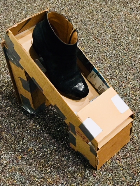
Figure 1: Cardboard Shoe Display Case (to test dimensions)
Once I figured out the design, I laid out the dimensions of what I will be laser cutting on my white board outside of my dorm room:Here are my dimensions for the design:
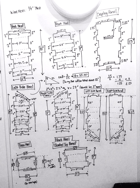
Figure 2: Heel, Display, and Side Panel Drawings and Dimensions
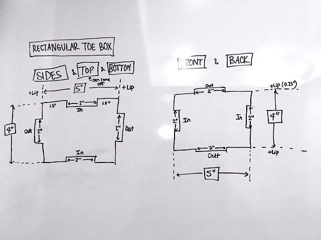
Figure 3: Toe Box Panels Drawings and Dimensions
I then translated the designs to digital form in Adobe Illustrator:
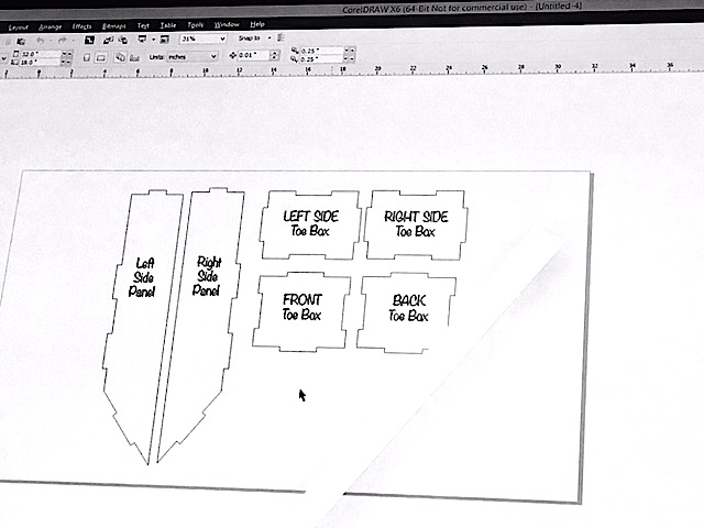
Figure 4: First Set of Display Case Panels to Cut
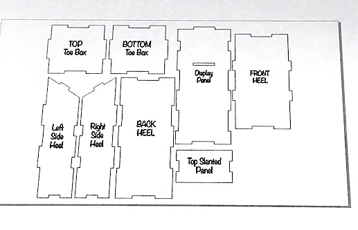
Figure 5: Second Set Ready to Cut
Finally, I went ahead and had the acrylic cut on the laser cutter in teh EDS shop:
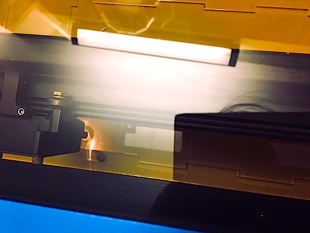
Figure 6: Laser Getting Started
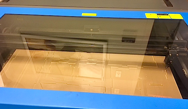
Figure 7: Laser Cut Pieces
I unfortunately forgot to take a picture of my finished shoe display case, except for a picture that has it with the rest of my final project display at the final presentation for the class. (Please see the final picture at the end of this page)
Designing and Making a Shoe!
I came upon a really great YouTube tutorial video that explains how to make shoes using my own foot as a last, with basic simple materials. Here below is the process of me making my shoe-form last with their instructions:
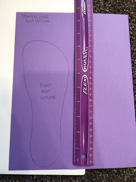
Figure 8: Starting Off by Outlining My Foot
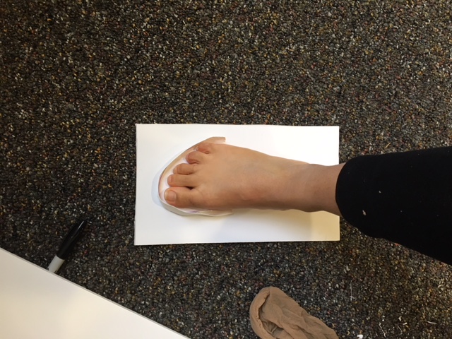
Figure 9: Duct Tape Lining to Provide Shape
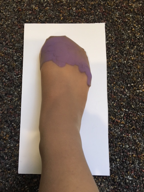
Figure 10: Adding Playdoh and Wrapping Foot in Nylon Sock
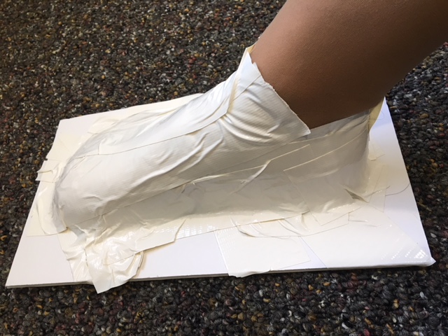
Figure 11: Wrapping my Whole Foot in Duct Tape
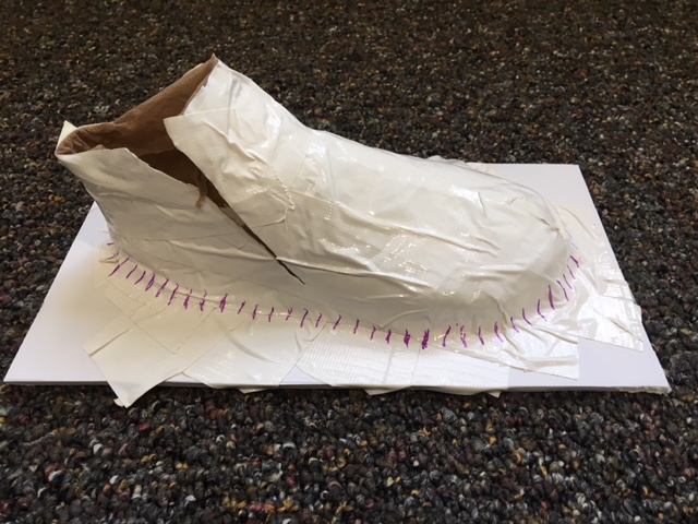
Figure 12: Removing my Foot
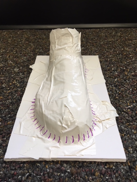
Figure 13: I have a Duct-Tape Foot-Shaped Last!
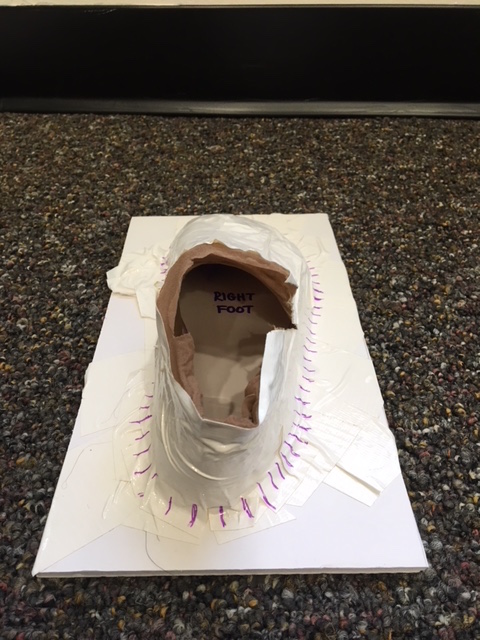
Figure 14: Back View of It Holding Its Shape
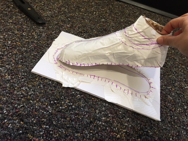
Figure 15: Cutting It Off the Foam Board
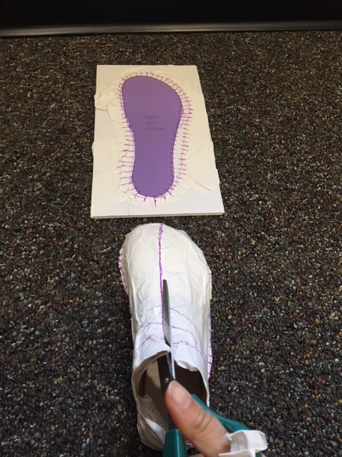
Figure 16: Cutting Down Centerline to Create Meane Forms
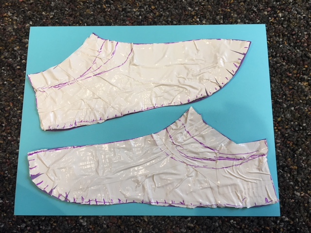
Figure 17: The Left and Right-Side Meane Forms of my Right Foot
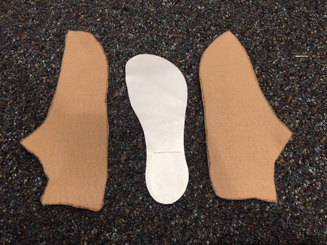
Figure 18: Translating my Dimensions to Shoe-Based Fabrics and Materials to Prepare for Sewing
3D Printing -- A Printed Heel
Next, I designed a 3D printed a hollow shoe heel (from Week 3) that would then house the electronics for my shoe. I wanted the heel to be made from clear plastic material, but unfortunately our EDS shop doesn't have clear plastic filament for our 3D printing machines, but, for now, I was able to design on Fusion 360 a tapered 3 inch heel that I printed on the Shindoh 3DWox machine in the lab.
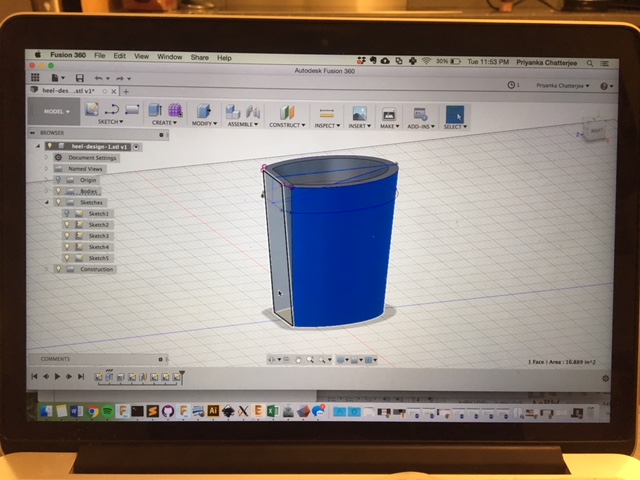
Figure 19: Designing the Heel in Fusion 360
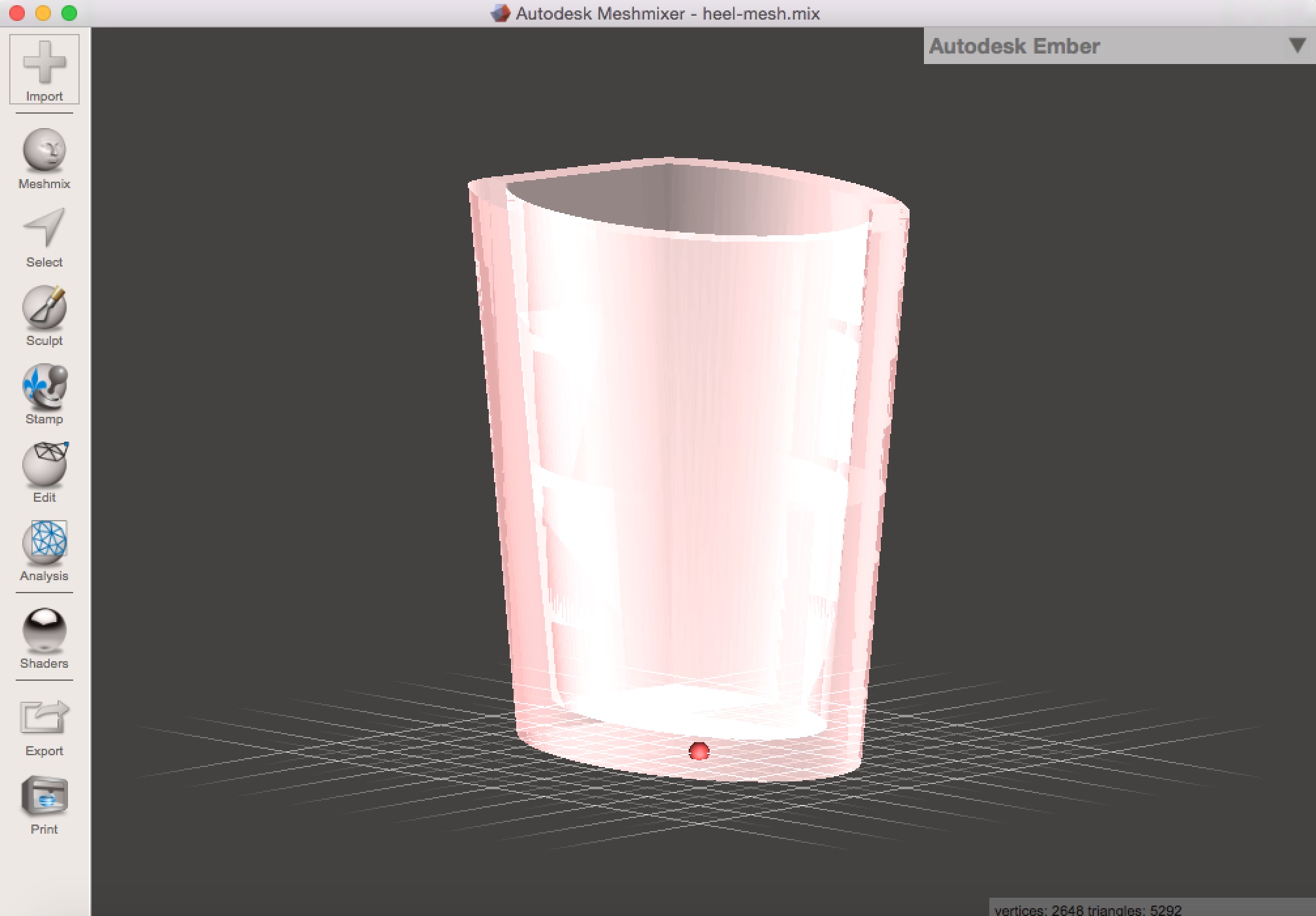
Figure 20: Uploading Design to Mesh Mixer
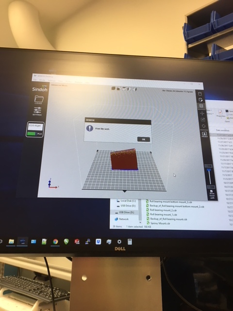
Figure 21: Uploading the Design on the Sindoh Software
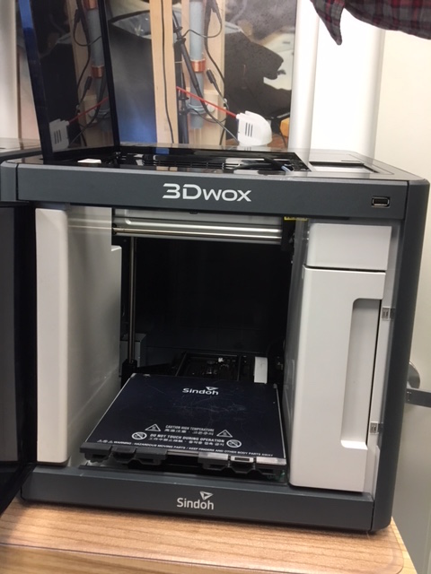
Figure 22: 3D Printer Bed is Ready!
Heel is ready to be printed!
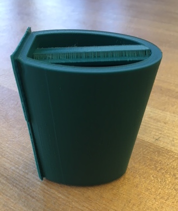
Figure 23: My Finished Printed Heel with Support Material
Electronics Design -- Output Device: RGB LED Strips!!
Now that I have some of the physical design work done, it was time to delve into the electronics! (Definitely not my forte, but it's now time for me to overcome my trepidation and jump right in!)
Since I am making a programmable LED shoe, I will need to work with LEDs as my output device! I started off with my Output Device week designing and testing Neil's RBG Hello World Board, but then I realized that I wanted to start even smaller, since electronics is still a bit daunting to me, and so I decided to make a board that interfaces with a strip of green LEDs, a strip of blue LEDs, and a strip of red LEDS.
Here below is my process for creating three strands of LEDs strips that I fabricated from little mini copper-plated boards with soldered-on LEDs and resistors "wired" in parallel with the LED connections that will be going to the Ouput Device pin of my ATTiny44 microcontroller and the resistor connections going to VCC.
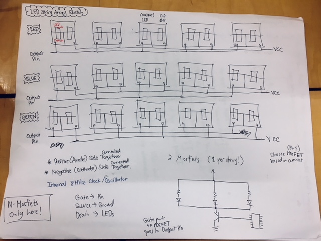
Figure 7: Initial Sketch for LED Strings
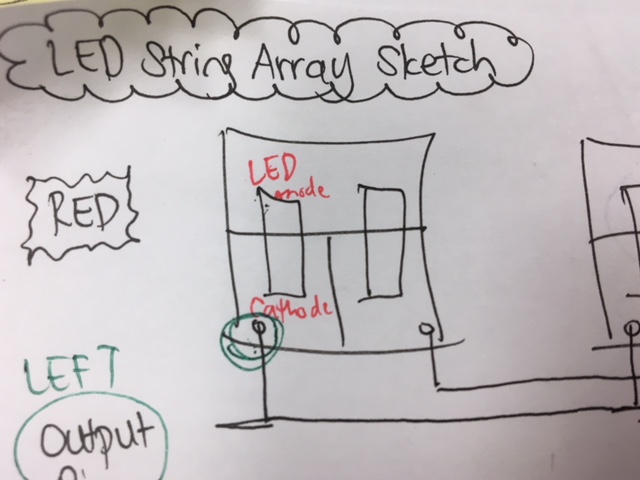
Figure 8: Close up of Mini Board
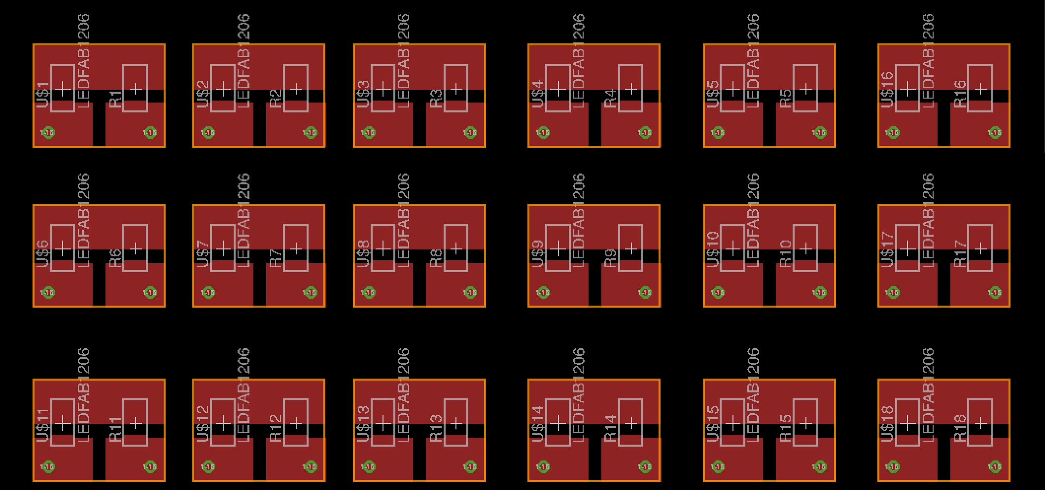
Figure 7: EAGLE Board Layout
Then it was time to start milling out the little boards on the Othermill
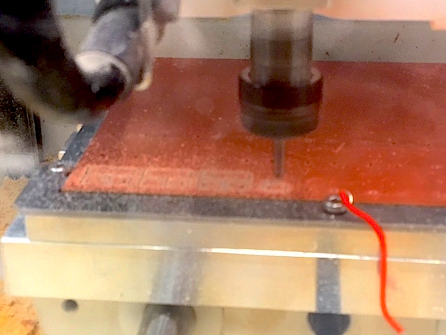
Figure 8: Milling the Little Boards!
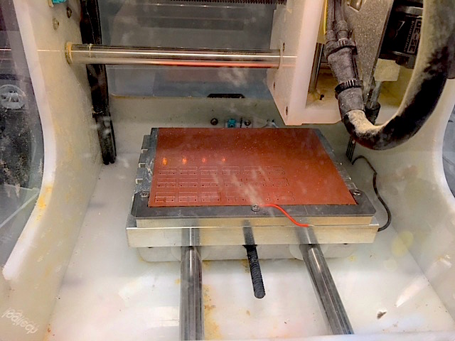
Figure 7: Boards are Milled!
Time to solder on the little PCB surface-mount components!
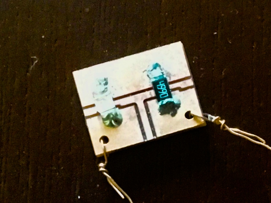
Figure 8: Close up of Little Board with LED & Resistor
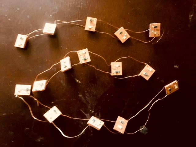
Figure 8: The Little Boards Strung Together -- One String Red, Green, and Blue, respectively
I promise, once they are powered, that I will have the copper wires insulated! (SHOCKING! I know :P)
From this, I was able to start exploring what input devices would be useful for the project and then start making my board!
Electronics Design -- Input Device: Ball-of-Foot Force Sensor
As I mentioned in my Input Devices week assignment, since I am making a shoe that lights up, I will need some sort of signal that commands WHEN & HOW the lights light up. Thinking along the lines of a shoe's form and function, I realized that one of the most common "responses" a shoe feels is the foot dyanamics of teh foot inside the shoe. As the shoe wearer is walking, she is applying downward gravitational force onto the sole of the shoe, which the shoe itself has to counteract with an equal & opposite force upwards towards the foot.
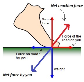
Figure 1: Net Forces on Foot
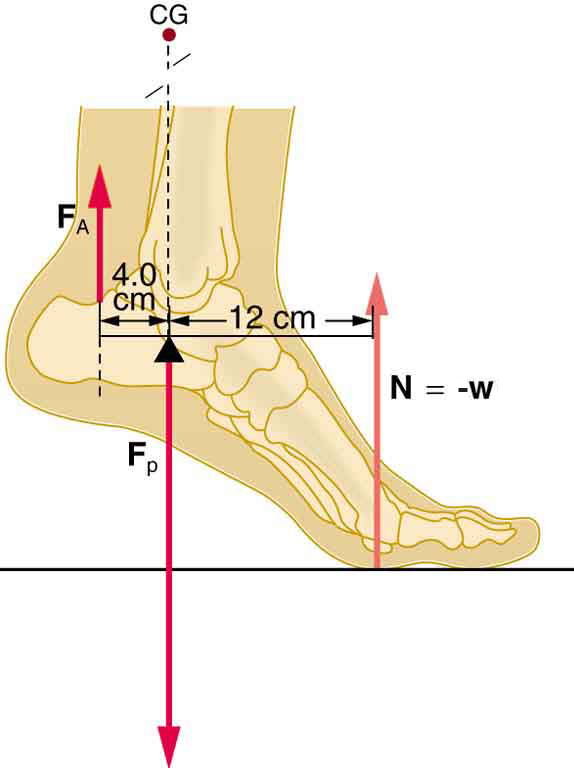
Figure 2: Forces and Torques on Foot
Depending on the height of a shoe's heel, the shoe's width, and other form factors, such reactive normal force on the foot can be highly uncomfortable to the wearer, and as I can say at least anecdotally, the higher the heel and the longer one stands int eh shoe, the pressure (Force divided by Area) seems to increase (or at least the cells on the bottom of one's foot are being strained and fatigued), which can cause severe discomfort.
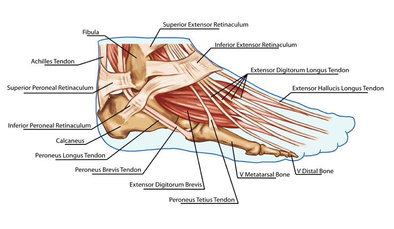
Figure 1: Foot Anatomy
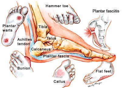
Figure 2: Foot Issues that May Result from Excess Pressure & Wear on Foot
I decided to better understand how existing devices measure force (in the mechanical domain) through an electrical signal (like voltage). Since I know a microcontroller can "read" voltage, I wanted to see how changing the force on some sort of "Force Sensor" (as my input device of choice) can influence the voltage readings read by the microcontroller and send these signals back to my computer translating back as actual force measurements. Adn then, based on those voltage readings, the microcontroller can send signals to my strip of LEDs to tell them to light up in a certain way so as to then indicate to the wearer, how much force she is feeling on her foot.
The vision is to indicate a strip of "green" color LEDS as a "low force" measurements from readings from my input device, "blue" coloring lighting as "medium force", and "red" color as "high force" measurements. This will effectively allow me to apply this device as a potential "Orthopedic Indicator" for people who suffer from foot pain.
For the actual electronics design, you can see the following schematics and board layout below:
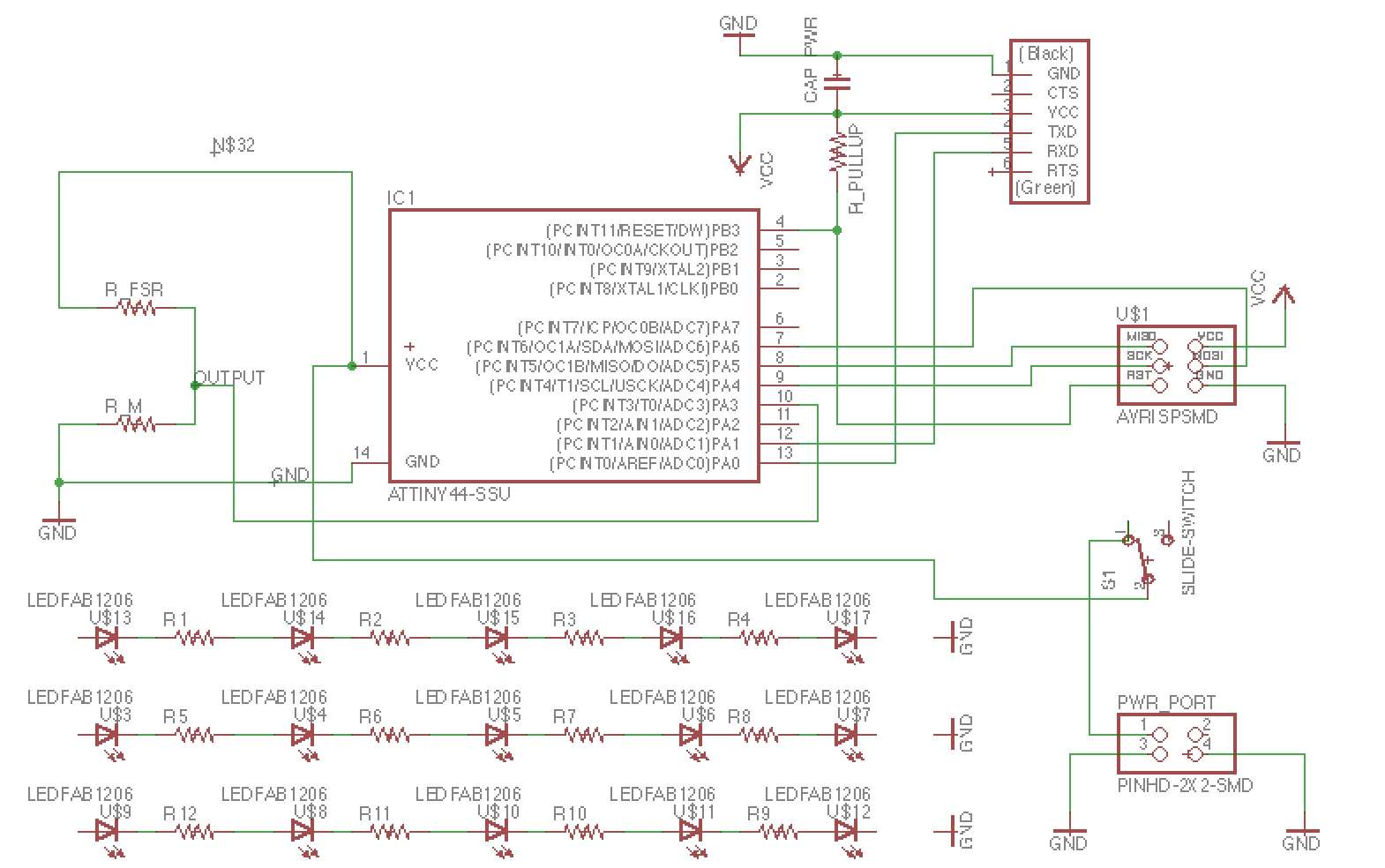
Figure 9: Initial Schematic
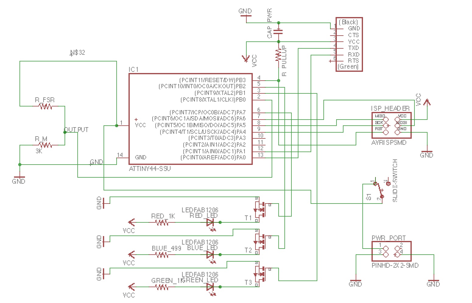
Figure 9: Final Schematic
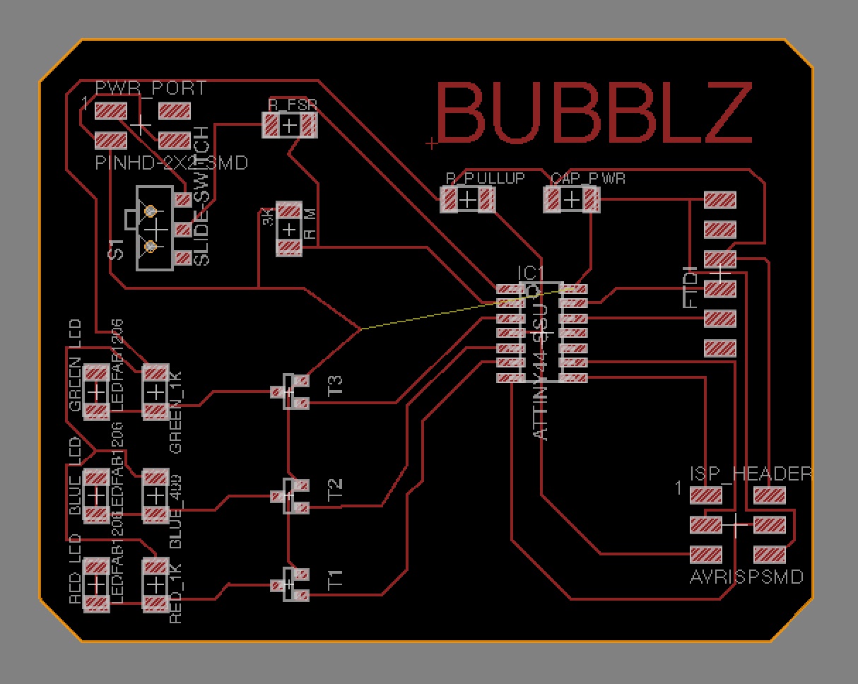
Figure 9: EAGLE Layout
Since at the time, I didn't have my force sensors with me, my mentor back home in Georgia (actually he is in Alabama, but close enough) did have some of the same sensors in his electronics lab, and so he did some initial resistance meaurements of the pads to give me a sense of what I would see when I was to step on the pads with different pressures.
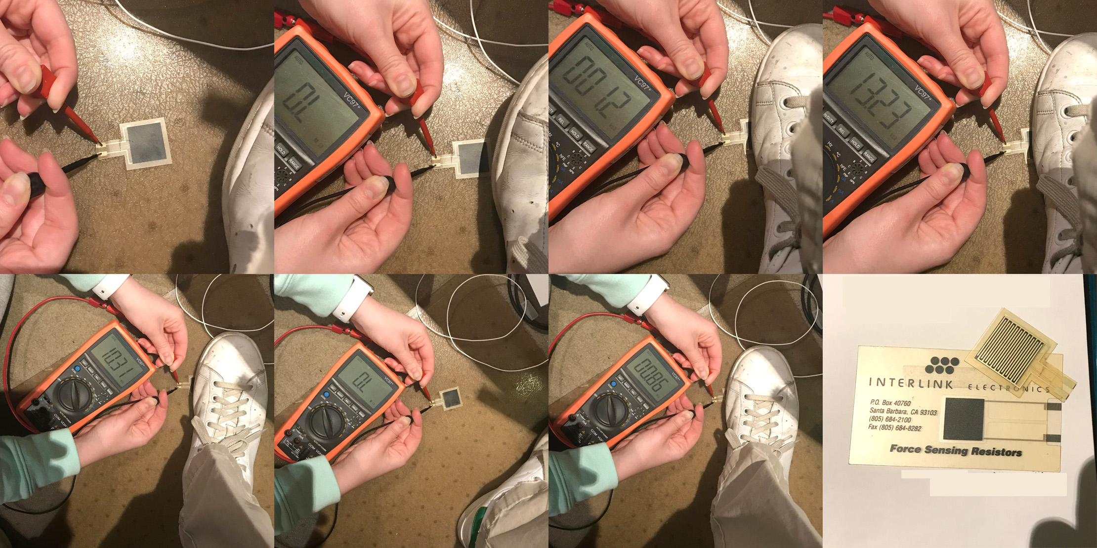
Figure 3: My Mentor Mr. Warren checking out the Resistance Readings when Applying Pressure to the Force Sensor
As for future iterations of this project, I would like to connect another output device that can ALTER the force the shoe wearer feels when wearing a heeled shoe, like inflatable bladders taht offset some of the normal force felt by the shoe, and thus decreasing the force felt by the wearer's foot and hopefully potentially increasing comfort levels.
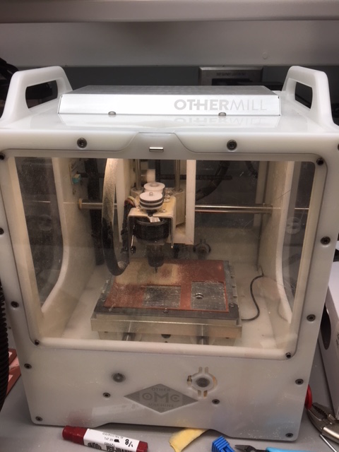
Figure 9: Milling on OtherMill
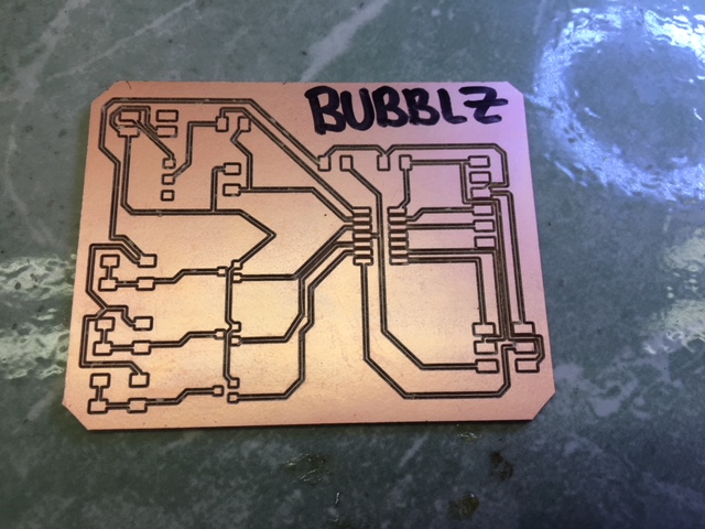
Figure 10: Milled Board
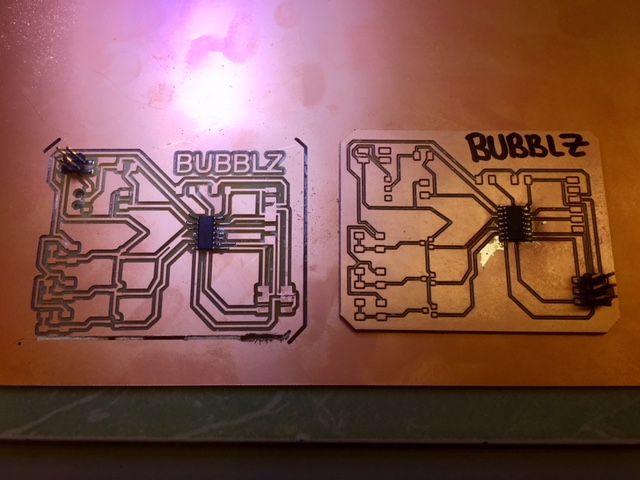
Figure 9: Bad Board Comparison
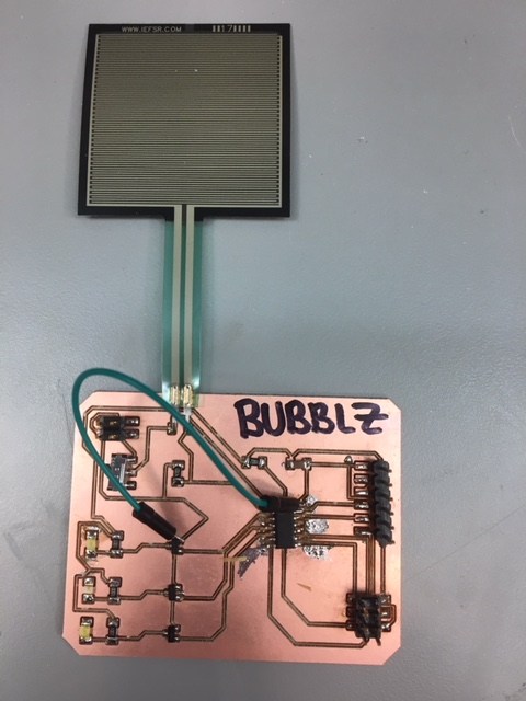
Figure 10: Finished Input-Output Board
Now that I have my electronics done as best I can (at least for the time being -- definitely planning on creating an even cleaner iteration during IAP), it was time to start programming.
Embedded Programming -- Computer Application for Manipulating LED Strips
Unfortunatley I didn't so far into this part of the final project, but I definitely plan on continue work on embedded programming, because it is so integral to the learnings in the class.
Nevertheless, I took a page from Sam Calish, who did a similar foot pressure sensor device for his final project, and looked at his code for his project and tried to manipulate it as best I could.
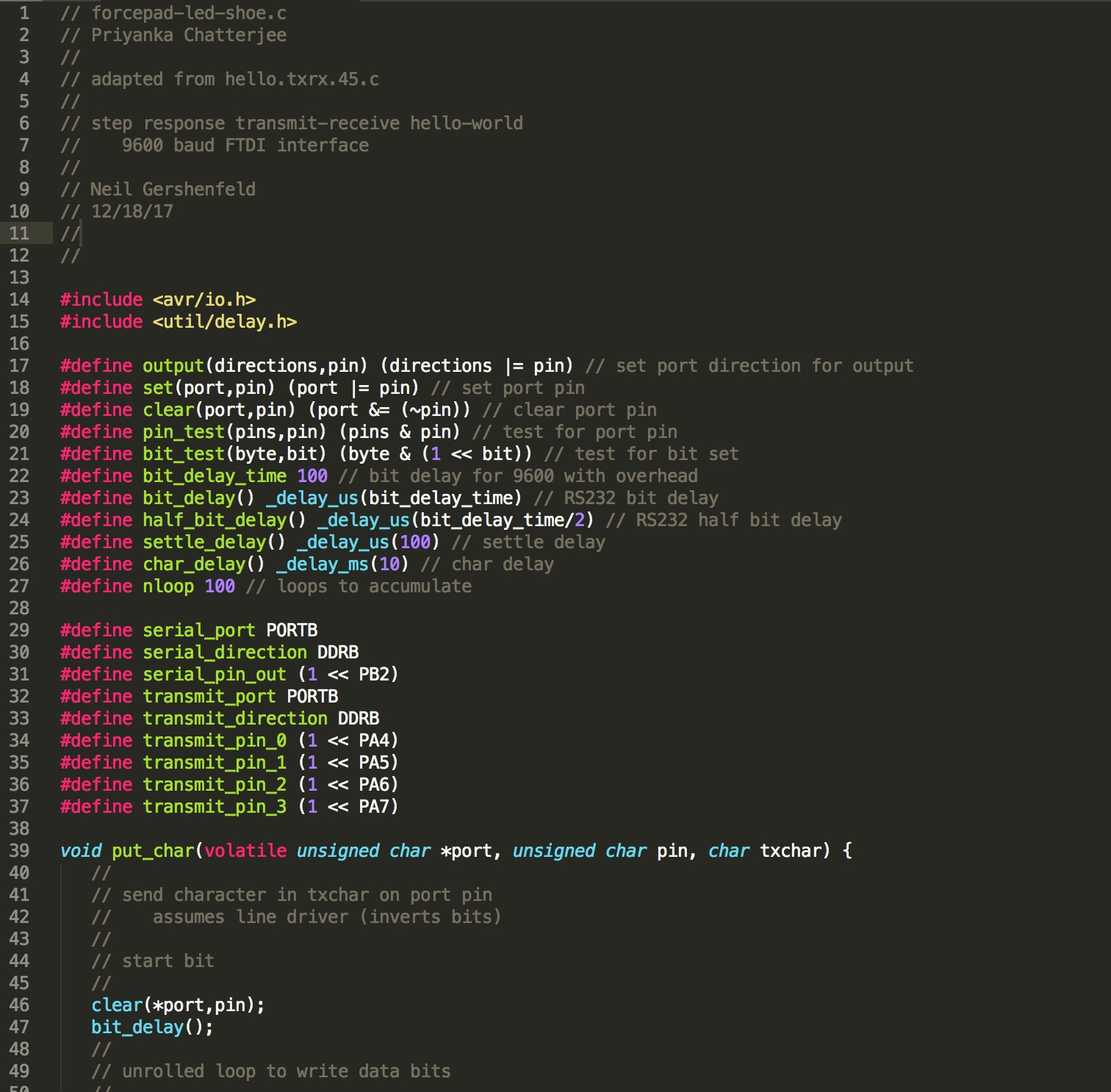
Figure 10: Initializing the Variables
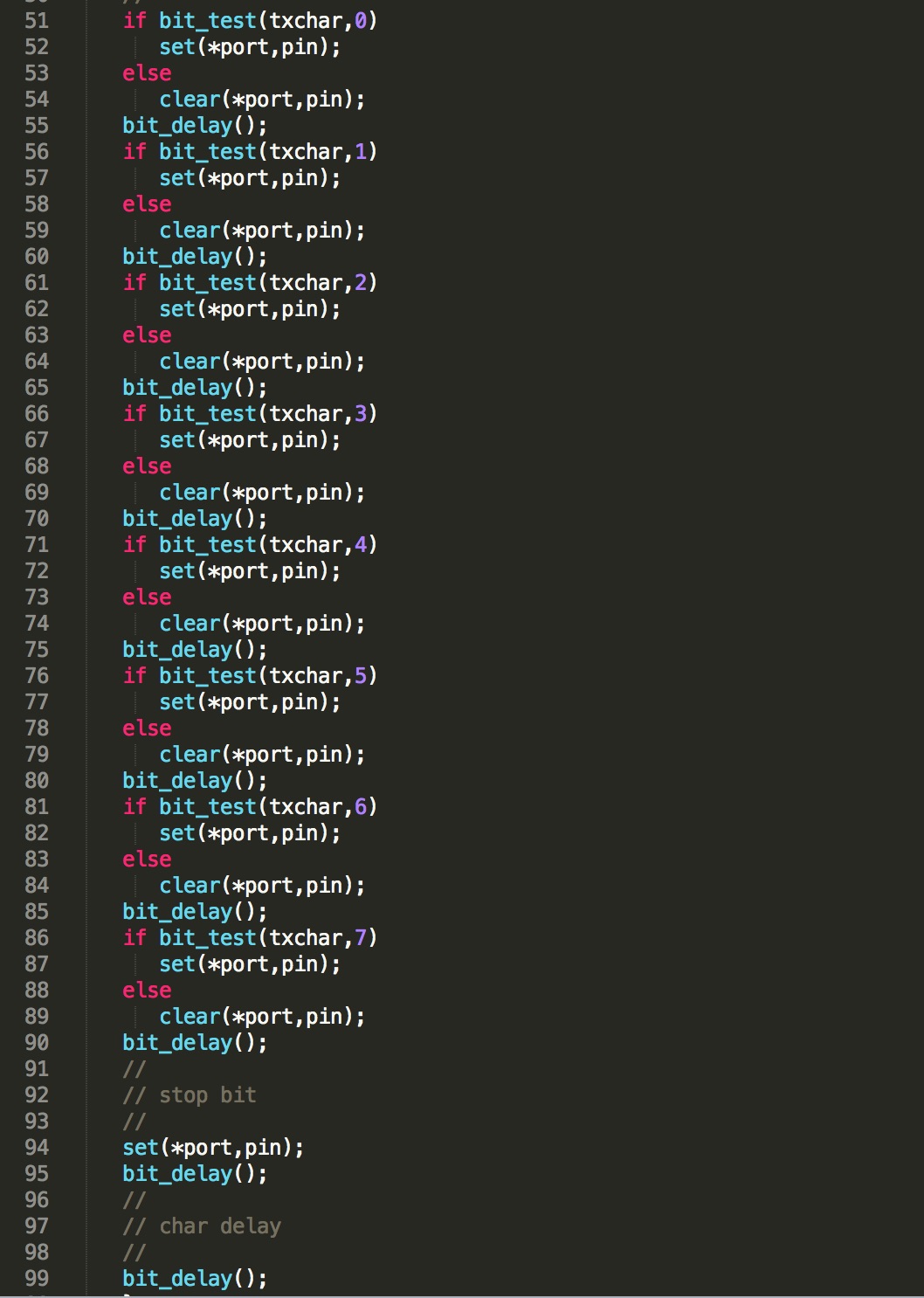
Figure 10: Setting the Bits, Ports, and Pins
![]()
Figure 10: Setting the Transmit & Receive Pins and Port Registers
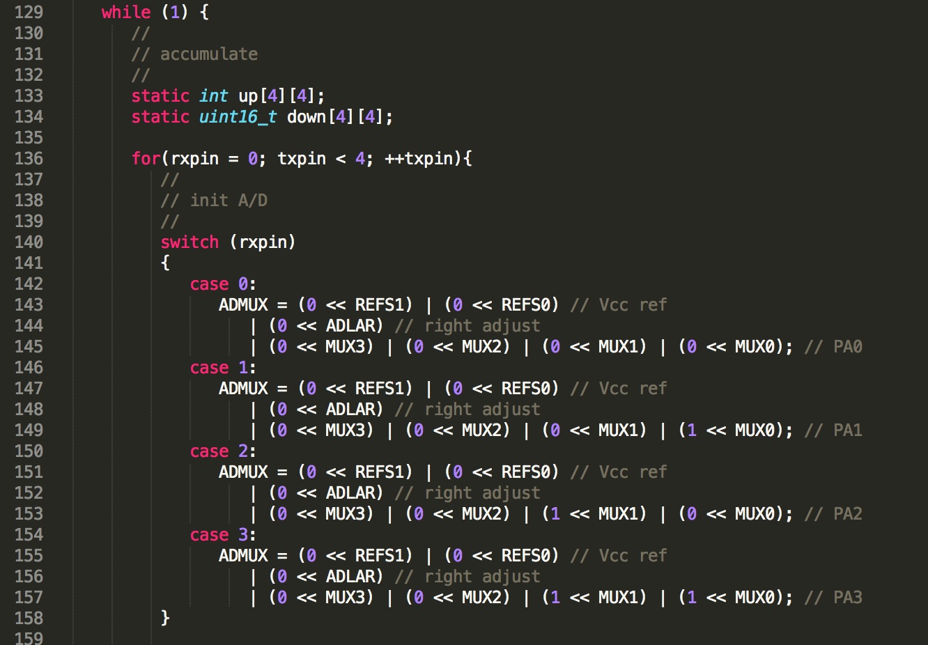
Figure 10: Adjusting the Networking Code
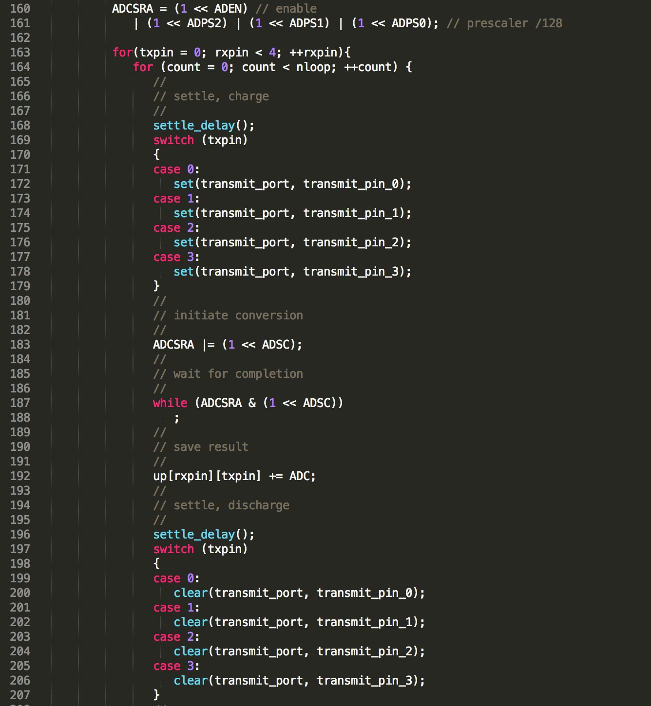
Figure 10: Initiating Conversation Code
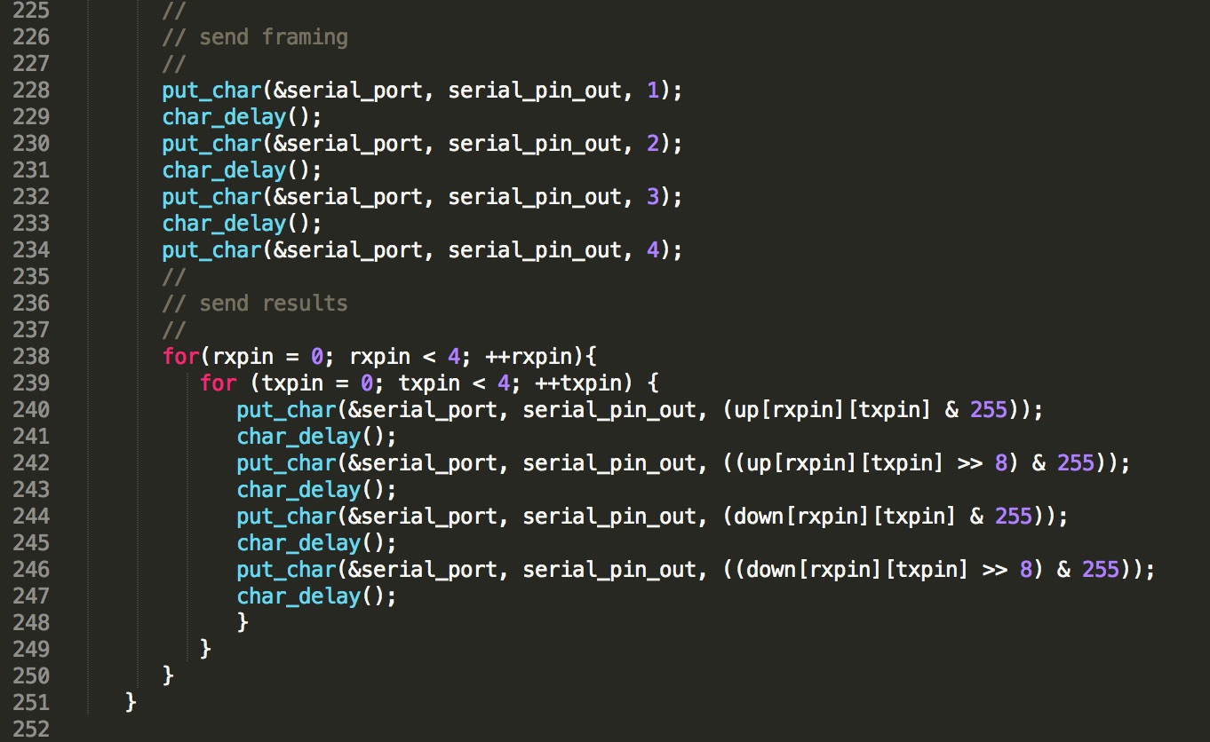
Figure 10: Sending the Framing
Application Programming -- Computer Application for Manipulating LED Strips
Again, this was also a point of limited gains, but if anything, I learned how to design an Android app on AppInventor that I plan to use for future iterations of my final project. The goal is to be able to control a set of LEDs embedded inside a thick and thin textile shell--based on the pressure sensed from a force pad embedded inside a ball of foot pad--for my LED shoe final project. Here is my start to learning App Programming in AppInventor (I'm getting excited about this and definitely looking to work with this more soon!)
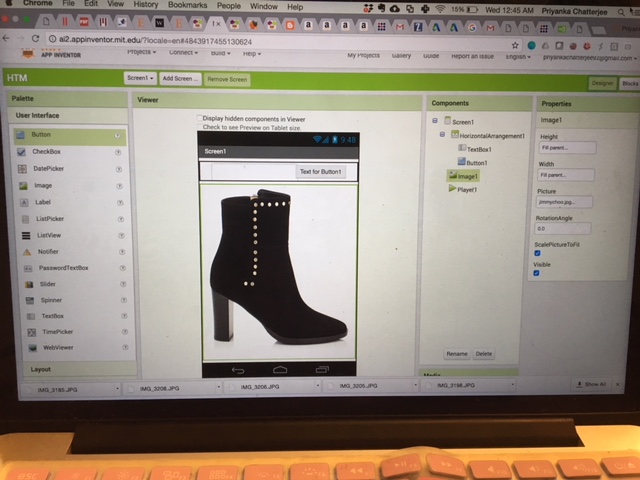
Figure 10: Designer Window where I want to include an Interface for my LED Outputs on my Shoe
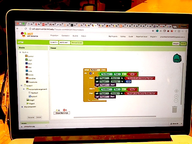
Figure 10: Coding App Section where I tell the App what to Do
Networking and Communications -- Computer App talks with Shoe!
Since it is crunch time, I wasn't able to go ahead with the BLE interface, nor anything wireless. But this is ok, because not only will I be delving into BLE / other wireless communication technology after the class (because, why not? and how cool!), for the class, I have decided to stick with wired communication between two devices -- My Computer and My Final Project Shoe.
The input device that I am using for my final project is a force sensor from Interlink Electronics that acts like a resistor, and which can then be connected to my PCB board in series with an already known-value resistor that I picked to limit current, yet still provide a reasonable power output for my final project's LED light strips. Basically, my goal is to get the force sensor readings sent to my computer as a list of voltage readings that can then be translated back to force measurements that would interface with my app.
I unfortunatley didn't get as far along as I wanted to on this front, but I do look forward to learning more about this and working on this very soon.
Now back to the physical design work to wrap it all up!
Molding and Casting -- Ball of Foot Pad
I went back to my "How to Make a Shoe" tutorial outputs, and took my High Heel Outsole design, created a copy, and then sketched out and then CADDed the ball of foot section of the outsole to then have it molded and casted. Here below, starting with the CAD of my wax mold, is the process for my molded and casted shoe sensor housing:
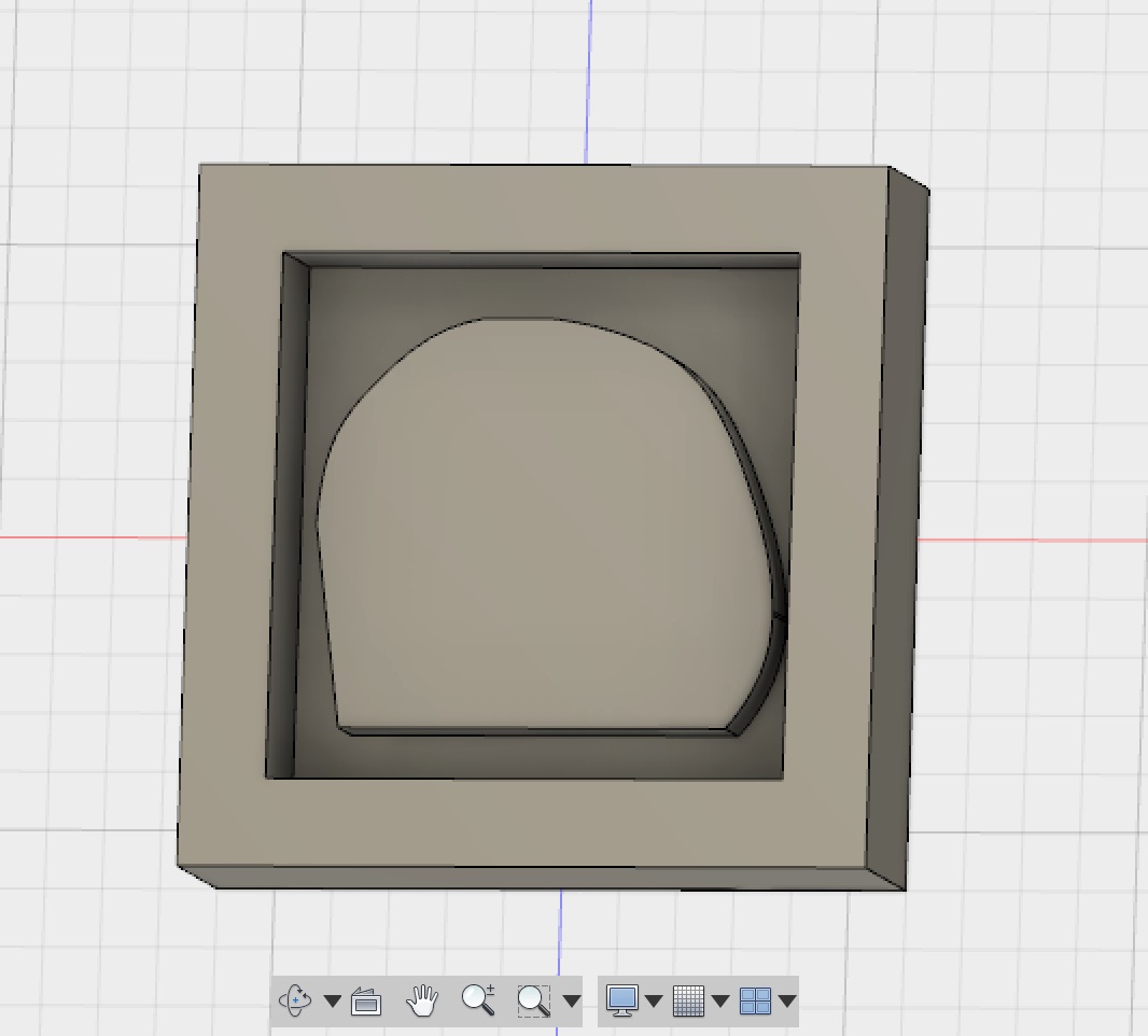
Figure 11: CAD Model of My Personal Actual Ball of Foot Shape in Fusion 360
I then went to milling the wax via FabMods with the Roland SRM 20 mini mill:
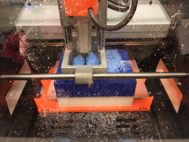
Figure 11: Milling the Wax
Unfortunatley the mold was too deep for the endmill in the Roland SRM20 colle, and so the endmill actually got jammed during the process of milling at the tail-end of the wax rough cut, and so, to save both time and the machine itself, I decided (since the mold doesn't need to be perfect at the moment) to just go with the rough cut cut mold, which was whatever had already been milled. Here below is the picture of my mold:
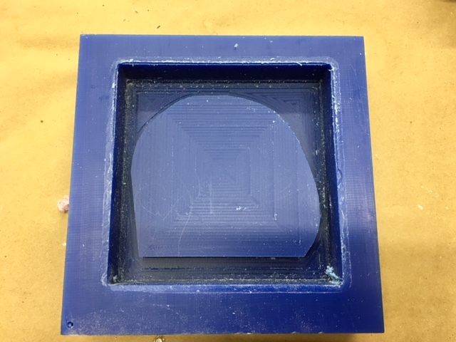
Figure 11: Wax Mold of Ball of Foot
I then went ahead and started mixing and pouring the Oomoo mateiral into the mold and preparing it to set overnight.

Figure 12: Me Pouring in the Oomoo Mold Material into the Wax Mold
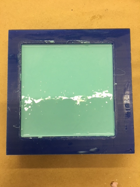
Figure 13: The Oomoo ready to Set Overnight
The next day, I took out the mold and checked how it turned out!
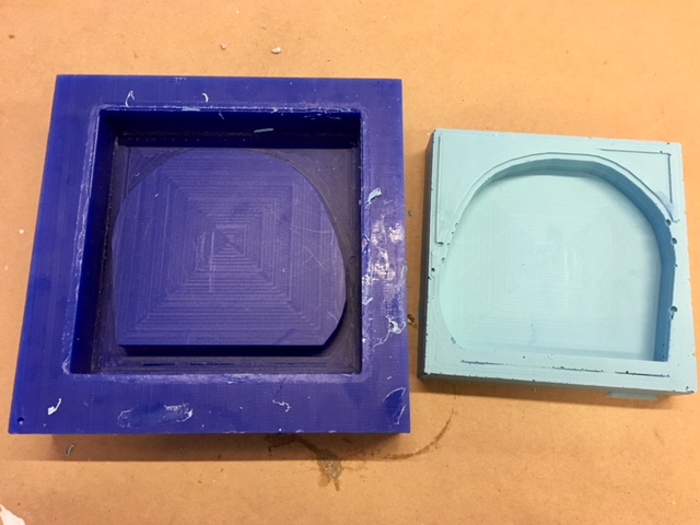
Figure 14: The Molds Ready for Continuous Casting
Not so bad, except for some bubble cavites at the side edges of the Oomoo mold. I think we can work with it for now, though.
The clear casting material was unfortunately a bit old and so had already started to harden over time despite being sealed and in a climate-controlled environment. Nevertheless, I was able to mix together the 2-part colloidal material together and let it set in the Oomoo mold that I created. You can see the materials themselves and the casted part below:
![]()
Figure 13: The Smooth-On Almost Clear Castable Materials
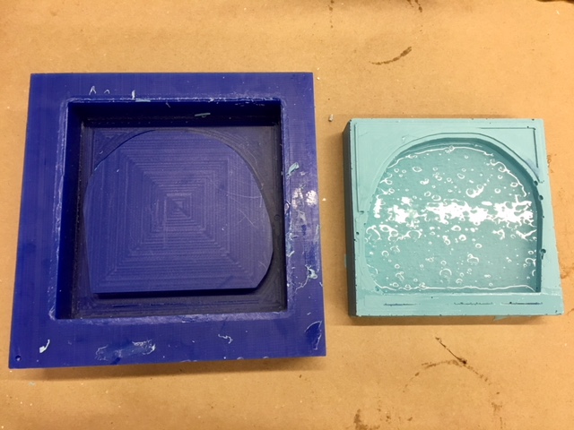
Figure 13: Clear Casting Material is Poured into Mold
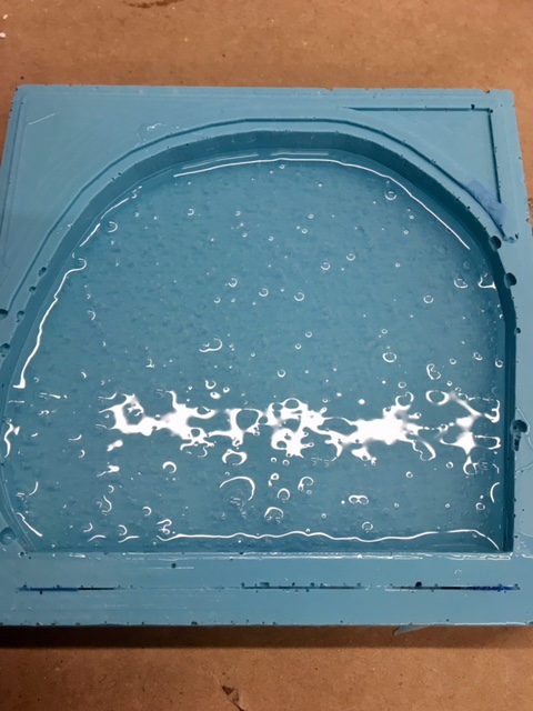
Figure 14: Close Up of Cast (with unfortunately quite a few bubbles)
I let the clear silicone cast set overnight so that it can harden and be ready to attach to the shoe, once it is constructed.
Composites -- My Shoe's Outsole to Form into a High Heel
My last section for this first embedded systems shoe project of mine was to make the outsole of the shoe actually hold it's shape.
First I needed to actually ensure that the shape is correct, so I milled out a piece of angled foam at the angle of a of a foot bed for 2 inch height on the SharkBot:
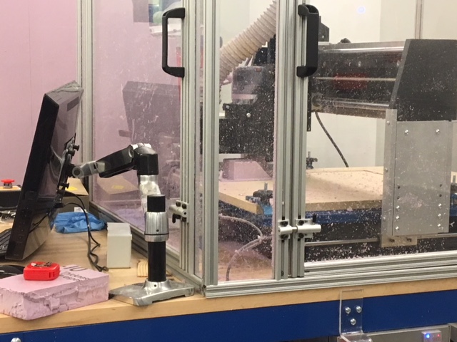
Figure 20: Sharkbot Milling
As you saw in my Composite's week page, I designed an outsole using light-guage burlap in the shape of my high heel outsole cutout and then lathered it with epoxy, covered it with aerated materials, and vacuumed sealed it to let it set overnight. Here below are some pictures from process to final composite product!
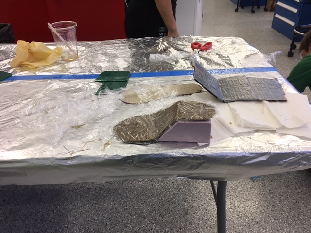
Figure 20: Readying the Layers
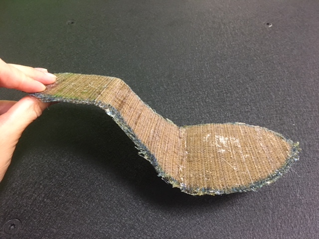
Figure 21: Final Composite Outsole!
Typically high heels are made by hammering in the leather with pins onto a wooden last in the shape of a foot. Since I couldn't find (nor afford online) a fancy wooden last, I decided to make my own with (none other than) clay and duct tape. I made one that fit on top of my composite.
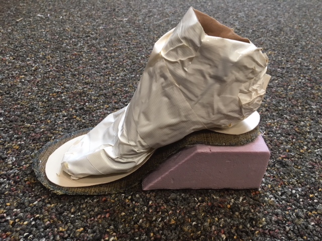
Figure 21: Duct Tape Last on Shoe Bed Composite and Foam Platform
Awesome! Now it is time to put together the Physical Shoe!
Finished Product for the Final Presentation
Finally it was time to put it all together. Here is how the final (but not completely finished) designs came out to be:
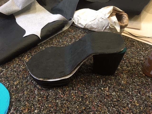
Figure 22: Shoe Heel and Bed Fabric-Covered Platform
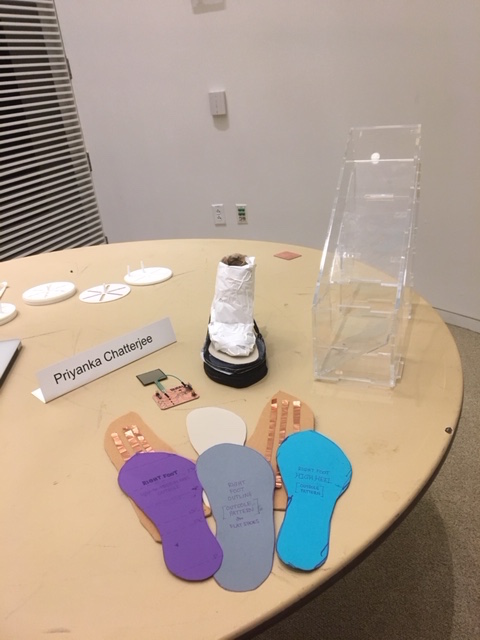
Figure 23: Setup for My Final Presentation
Although it didn't fully work, I really put my whole heart into this project, and am excited to see how it will be turning on in later iterations to come! So please stay tuned!
Acknowledgements
I would like to thank Neil for his instruction in the class, Gavin for his patience and understanding when I would do everything wrong in lab and break all the things (really Gavin, you rock!), and then of course my EECS section who really pulled through and were willing to answer all of my questions and help me through the craziness of How to Make (Almost) Anything. It really was a pleasure being in this class, and now I feel practically invincible. Thanks again!