Week 10: Input Devices
"Priyanka Learns HOW TO MAKE Input Signals Transmit to a Microcontroller!"
For my tenth (almost there!) assignment for How to Make (Almost) Anything, I decided to continue working on my final project and design a module that will be useful for the ultimate result for my project. I looked ahead to what applications are useful for my final project, and reaized, since I am making a shoe that lights up, I will need some sort of signal that commands WHEN & HOW the lights light up.
Thinking along the lines of a shoe's form and function, I realized that one of the most common "responses" a shoe feels is the foot dyanamics of the foot inside the shoe. As the shoe wearer is walking, she is applying downward gravitational force onto the sole of the shoe, which the shoe itself has to counteract with an equal & opposite force upwards towards the foot.
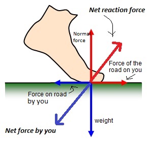
Figure 1: Net Forces on Foot
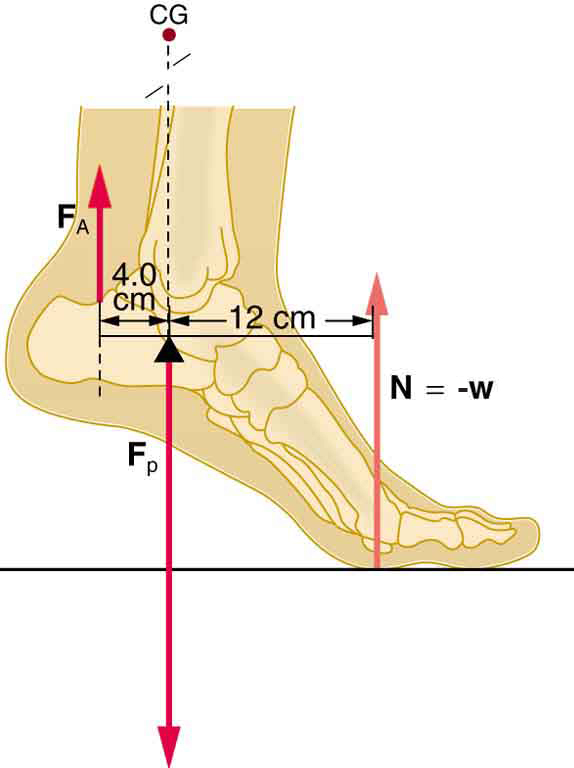
Figure 2: Forces and Torques on Foot
Depending on the height of a shoe's heel, the shoe's width, and other form factors, such reactive normal force on the foot can be highly uncomfortable to the wearer, and as I can say at least anecdotally, the higher the heel and the longer one stands int eh shoe, the pressure (Force divided by Area) seems to increase (or at least the cells on the bottom of one's foot are being strained and fatigued), which can cause severe discomfort.

Figure 3: Foot Issues that May Result from Excess Pressure & Wear on Foot
To start off my Input Device adventures, I decided to better understand how existing devices measure force (in the mechanical domain) through an electrical signal (like voltage). Since I know a microcontroller can "read" voltage, I wanted to see how changing the force on some sort of "Force Sensor" (as my input device of choice) can influence the voltage readings read by teh microcontroller and send these signals back to my computer translating back as actual force measurements. Adn then, based on those voltage readings, the microcontroller can send signals to a strip of RGB LEDs to tell them to light up in a certain way.
Since this is just Input Devices week, however, I decided to take a look at Neil's step response boards and determine how they work and what do the microcontrollers on the boards allow me to do if I were to connect an Input Device onto them.
I went ahead and first fabricated the daughter boards for Loading and Transmit/Receiving "Step Response" input signals.
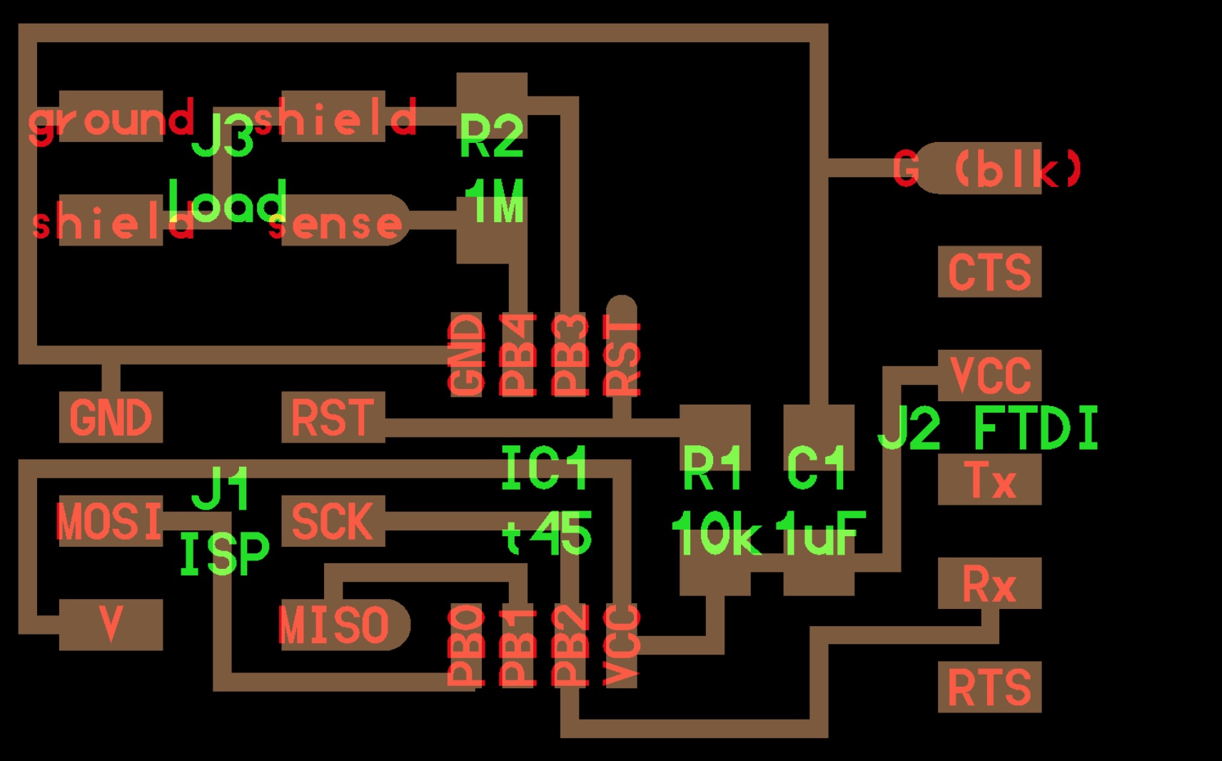
Figure 4: Board Layout for Loading PCB
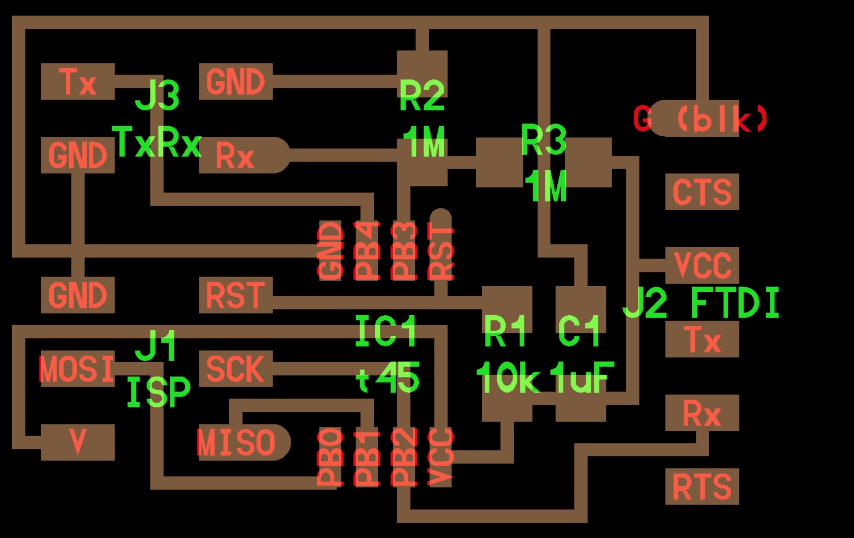
Figure 5: Board Layout for TXRX PCB
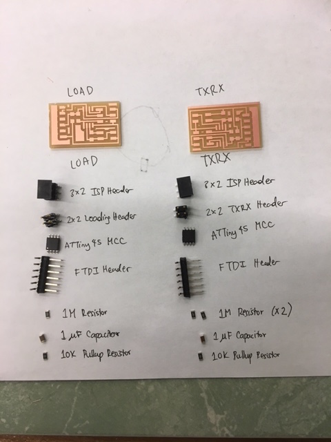
Figure 6: Acquiring & Arranging the Components for Loading & TXRX PCB
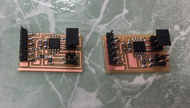
Figure 7: Final Physical Boards to Use for Loading & TXRX Communication of Input Devices
I specifically chose to recreate the step response boards becuase I ultimately want to to measure force / pressure through voltage levels read by the microcontroller. Through the help and wisdom of TA Anish Athalye, I learned that in order to read varying voltage levels from an force-based input device, I will need to create a voltage divider circuit where I have a known-value resistor and a "variable" resistor connected in series, and in between the 2 resistors, the MCC (microcontroller) is connected to read the voltage leels that change between teh two resistors (coming from the variable resistor).
I know that I choose the fixed resitor to limit current(to protect the PCB components from being fried) but to also allow for enoguh current to flow so a singal can be read and the board has sufficient power to do so. But what would I use as my "varible" resistor? In a typical, simple circuit board, I could use a potentiometer, but it wouldn't allow me to do anything useful for my project, as I would be manufally changing the resistance level -- although it would give me teh MCC voltage readings and how it varies with the manually changing (and thus controllable) resistances.
But there are more useful Input Devices out there that I can test and use for a more interesting result and final project application.
I came upon a set of "Force Sensitive Resistors" by Interlink Electronics and realized that these would be perfect for my application, where the "force pads" act as variable resistors when I am applying force onto them adn they then alter the voltage level readings read by the microcnorller to indicate a signal of force being applyed to the pad.
The Interlink Electronics Datasheet had a very useful description of the math, graphical schematic, and output curves for the FSR acting as the variable resistor in a voltage divider circuit:
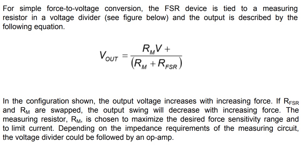
Figure 10: Mathematical Explaination of Voltage Divider
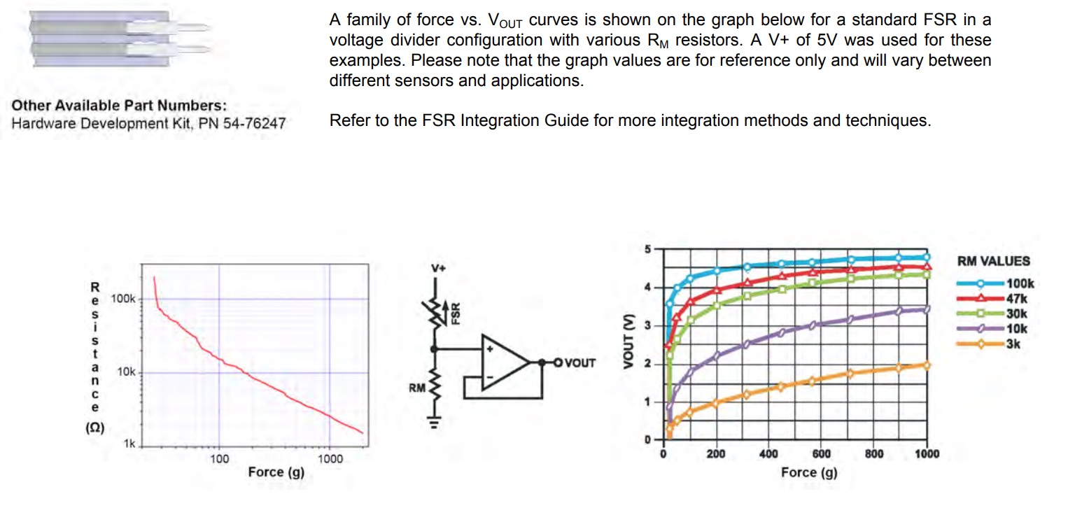
Figure 10: Schematic & Force Curves with Varying Resistance & Output Voltage
Since these look like a good bet for my project, I asked EDS Lab Instructor Gavin to buy me the following Force Sensitive Resistors by Interlink Electronics that I will be using for my final project:
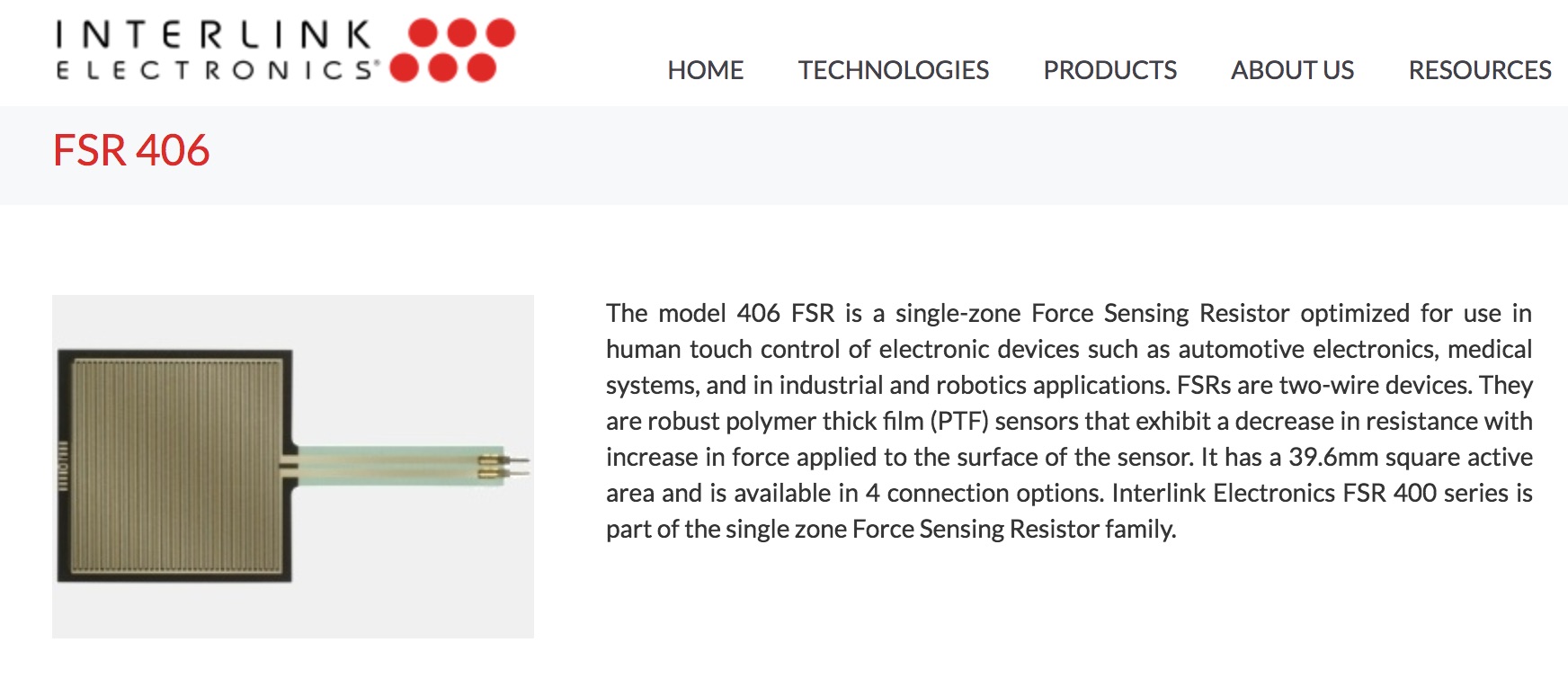
Figure 10: Square Single-Zone FSR from Interlink Electronics

Figure 10: Circular Single-Zone FSR from Interlink Electronics
I am lucky to have a good friend and mentor, Mr. Warren, who is a licensed PE in Electrical Engineering who has helped me understand electronics and build things over the years. He had some of these sensors with him, when I told him about my project, and so he was very nice enough to do some initial resistance readings for me from his home in Alabama:
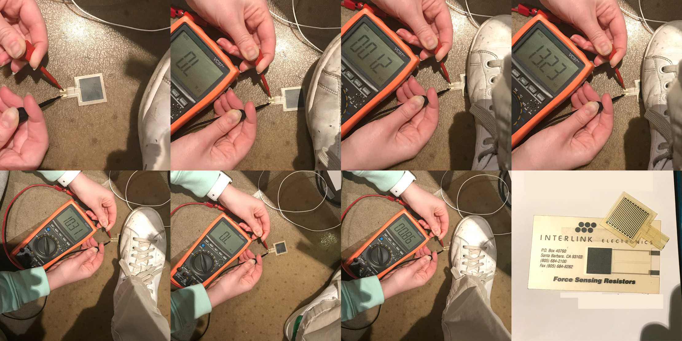
Figure 10: My Mentor Mr. Warren checking out the Resistance Readings when Applying Pressure to the Force Sensor
This gave me a general idea of what I will be working with for my final project, and now I will work off of this knowledge and design to build my voltage-divider-based force sensor embedded system with my LED strip output device for my final project. This voltage divider circuit will integrate both my input device and output device systems onto one board, so please check my Final Project Documentation Page for more progress on this front!