Week 12: Networking and Communications
"Priyanka Learns HOW TO MAKE Two Systems Talk to Each Other!"
For my twelfth assignment for How to Make (Almost) Anything, I tried to do as much as I could with getting two processors (either wired or wireless systems) to "talk" to each other. It was definitely a difficult task, but I am up to the challenge.
I first learned what it means for two systems to talk to each other, which is DEFINITELY NOT TRIVIAL. For my final project, I want to have the ability for commands sent from Bluetooth on a phone app dictate what LED colors on my LED shoe actually light up. I will ultimately want to set up a system where a board that I create communicates with my shoe LED array wirelessly.
I plan to use a Bluetooth Low Energy module to the board that can read voltage data and have a 5 pin header connected to a PWM output of the ATtiny44 so that I could send a 60 kHz simulated WWVB signal over the port to an antenna connected to the header. The board will then be connected to a 9V battery with wires. The NRF52 module can then connect to the 5 pin header.
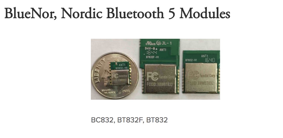
Figure 1: Bluetooth Module
I plan to also create a board that can sync with Bluetooth LE like the one shown below from Adafruit Industries:
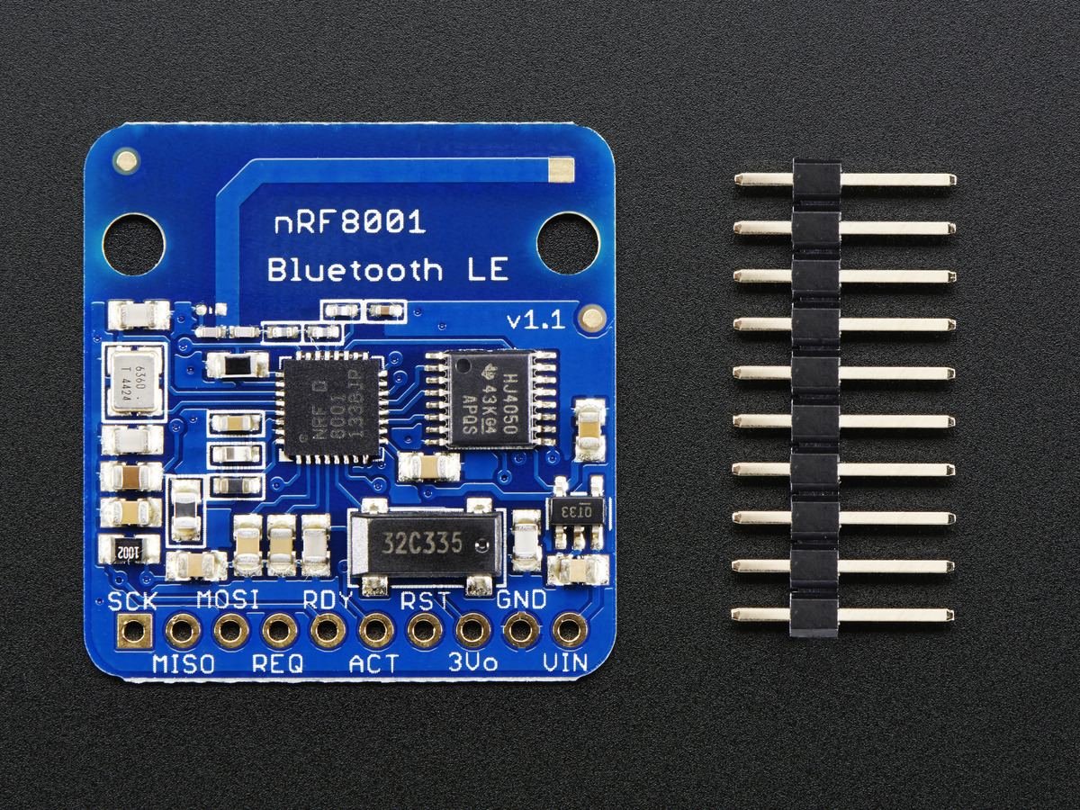
Figure 2: Adafruit BLE Board
The idea will be to do a Bluetooth connection between the low energy module and the bluetooth device in my iPhone, which can be read by a simple Bluetooth communications app already available on the App Store like LightBlue Explorer, and be able to control my LEDs in this way, like shown below:
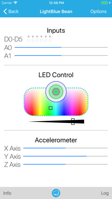
Figure 3: Light Blue BLE System
Ultimately want to create something like below, where an LED matrix can be controlled over BLE to sync with an Android App.
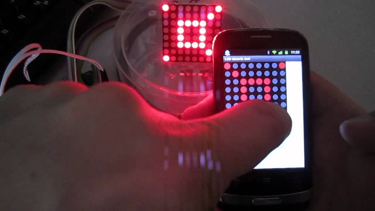
Figure 4: Matrix Control
To be continued!
UPDATE!
Since it is crunch time, I wasn't able to go ahead with the BLE interface, nor anything wireless. But this is ok, because not only will I be delving into BLE / other wireless communication technology after the class (because, why not? and how cool!), for the class, I have decided to stick with wired communication between two devices -- My Computer and My Final Project Shoe.
The input device that I am using for my final project is a force sensor from Interlink Electronics

Figure 5: Force Pad System -- Pad, Board, and Computer
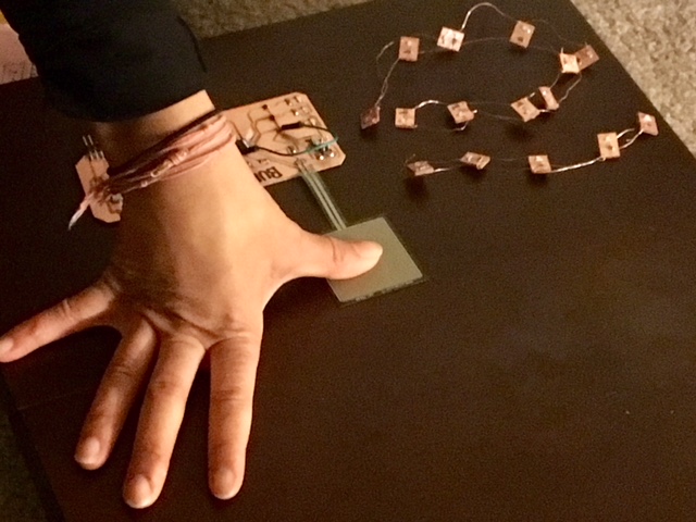
Figure 6: Me Applying Pressure onto the Force Pad

Figure 7: My Code for Obtaining the Voltage Readings and Displaying on my Computer

Figure 8: Voltage Readings Shown on Screen!
AWESOME! My next steps after this class is to incorporate BLE detection into the system and then translate the voltage readings into actual force values that can be read on an iPhone App. I am really excited to learn more about networking & communications so that I can become a true pro at embedded systems in the near future!