Week 2: Electronics Production
"Priyanka Learns HOW TO MAKE a Programmer"
For my second assignment for How to Make (Almost) Anything, I learned how to mill out and solder on components onto a copper plated epoxy glass PCB substrate for creating a USB board from scratch! It was really fun learning how to use the baby milling machine, but I realized quickly that there are many ways to make mistakes.
And mistakes were made.
First things first -- The group assignment!
Group Project: Calibrating the Mini-Mill for creating a USB out of a Copper-Plated Epoxy Glass PCB board
The first thing we did for this week was to take a look at the machine that we will be using to create the board that we will then populate with components, like a microprocesser that we will then program.
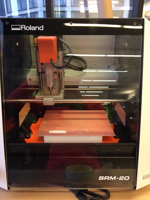
Figure 1: Setting Up the Roland SRM 20 Mini Mill
The process requires us to use both a 1/32'' end mill (shown below inside a spool of tape that we use to mount the copper plate onto the test bed) to mill out the outer rim of the board and a 1/64'' end mill to engrave the traces in the board. The traces were etched first, and then the outline (so that the traces are placed properly and there minimizes the possibility for the board to shift once it gets cut out)
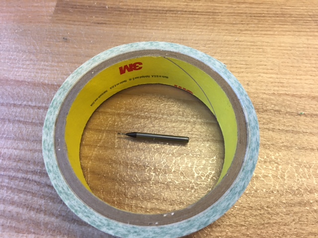
Figure 2: 32'' End Mill to Cut the PCB's Outer Edge
Now that we have the tools, we can now start getting used to Neil's very software the connects the hardware to the software we need to mill out the board accurately. The software called MODS was then connected to the mini mill, which then calculated the toolpath of the end mills from the inputted PNG files of the traces and outline of the board.
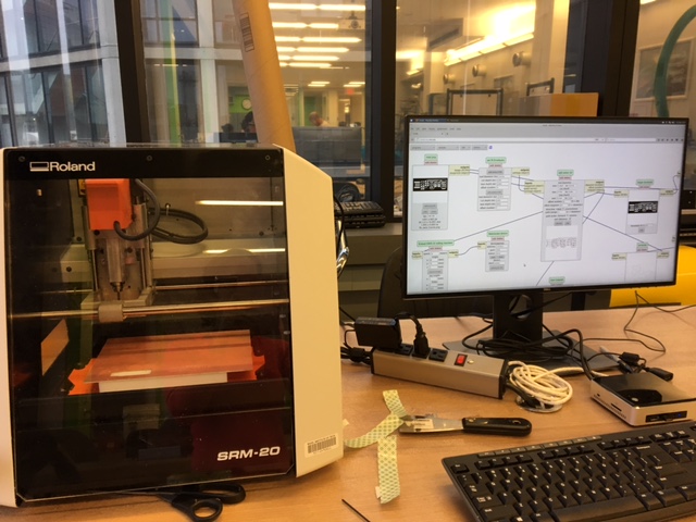
Figure 3: Setting Up Mods for the Roland SRM20
Before we start diving into the actual milling, we have to properly setup the end mills and the positioning of the spindle properly above the copper plated epoxy glass PCB board material. First the PCB board is firmly taped with double sided tape onto a plastic bed. Then, the correct end mill (the 1/64th first!) needs to be screwed into the spindle. But first we need to make sure there is clearance to properly set it up. Once the end mill is screwed in (using a set srew and a long thin hex screwdriver) then we orient the spindle (in the X-Y axes) over the copper-plated board to have enoguh room to mill out the board. Then we need to calibrate the Z-axis, so that the end mill properly etches the traces. For this, we carefully lower the spindle in the Z direction using the MODS software interface. Once it is just hovering over the board, we then carefully unscrew the spindle slightly and then manually lower the end mill onto the top of the board. Squeezing the mill slightly down onto the board will screwing it back into place in the spindle is our last step before we go back to MODS, calculate the toolpath, and then run the file to etch the traces. Once the traces are done, we redo the process with the 1/32'' end mill to mill out the board outline. Here is a picture of the process in action below.
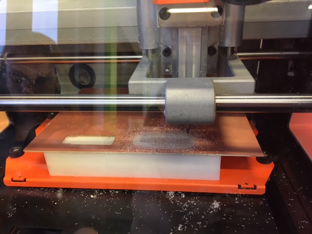
Figure 4: The Traces are being Milled!
Once I was comfortable with the process, it was time to get started with the Individual Project!
Individual Project: Making an In-Circuit USB Programmer!
For my individual project, I first etch and mill out my board, solder on the components, and then input a ready-made program to complete the creation of a homemade USB programmer!
Despite the excitement, it took some tries before I got the board milled out properly. Here below is my first attempt where -- probably due to not calibrating the "jog height" properly, I only etched out part of the board, while the rest was underetched.
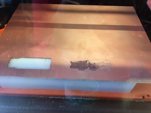
Figure 5: A Sad Half Etched Board
Sadly, the second try wasn't much better --> the board barely etched at all!
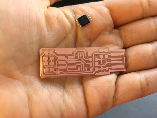
Figure 6: A Pretty but Underetched Board
I realized that it was likely that I wasn't putting enough pressure onto the 1/64'' mill (in fear of breaking the tip!) and so it wasn't etching through all the way to the epoxy resin glass. Nevertheless, I didn't give up, and gave it another (hopefully final) try.
I am a big believer in zero (or at least minimal) waste, so (despite all the attempts and attempts from others using a lot of the copper-plated boards) I decided to use the unmilled part of an old copper plate, and go for it. I had to do a weird taping job, but at least it saved my conscience. Here it goes...
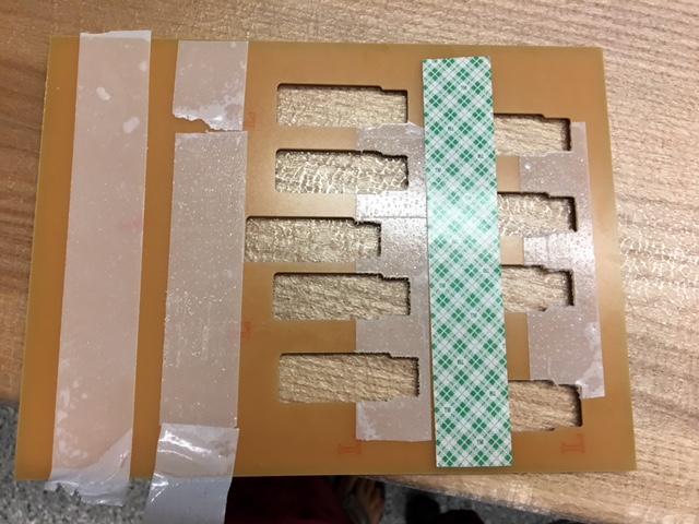
Figure 7: Saving Material by Using an Old Copper Plated Board
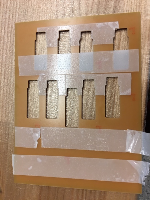
Figure 8: More Tape
It actually finally worked! I guess third times the charm! Finally the traces were etched all through and I was ready to move onto the next steps!
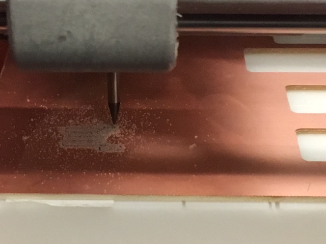
Figure 9: The Traces are Actually Etching All the Way!!
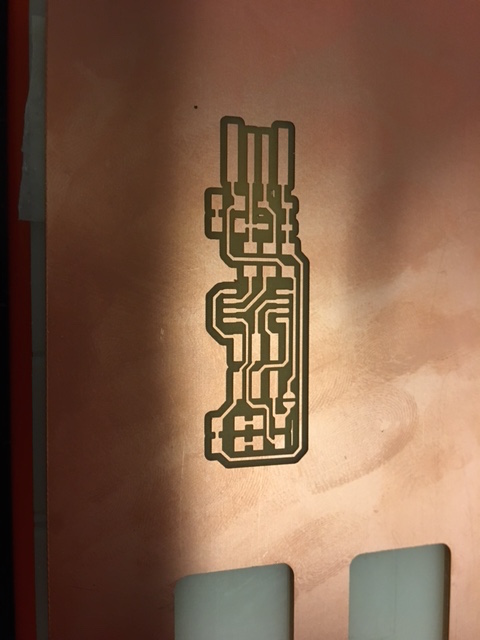
Figure 10: Wee!! Finished Traces Looking Good :)
Here is a look at all three of my board milling attempts! (It was a good learning experiment at the very least)
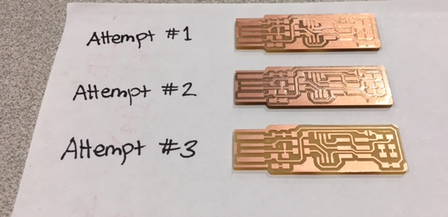
Figure 11: The Saga of my Electronics Adventures: Half Etched --> Underetched --> Fully Etched Boards!
The components that were given to us are as follows: 1x ATtiny45 or ATtiny85 2x 1kΩ resistors 2x 499Ω resistors 2x 49Ω resistors 2x 3.3v zener diodes 1x red LED 1x green LED 1x 100nF capacitor 1x 2x3 pin header
I started off soldering the microprocessor, and then I ran out of time and plan to finish the soldering and programming after class on Wednesday. Nevertheless, here is the microprocessor on the board, which was done using a soldering iron station.
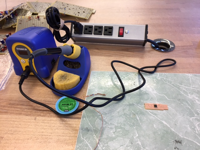
Figure 12: Soldering the Microprocessor
Once I got myself going with relearning soldering, I used a previously-made ATTiny Programmer board as a template to help me "stuff" my own board.
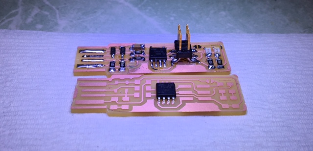
Figure 13: Comparing another Programmer Board to Help Me Stuff My Own
Here I go chugging along at stuffing my board at the soldering workstation.
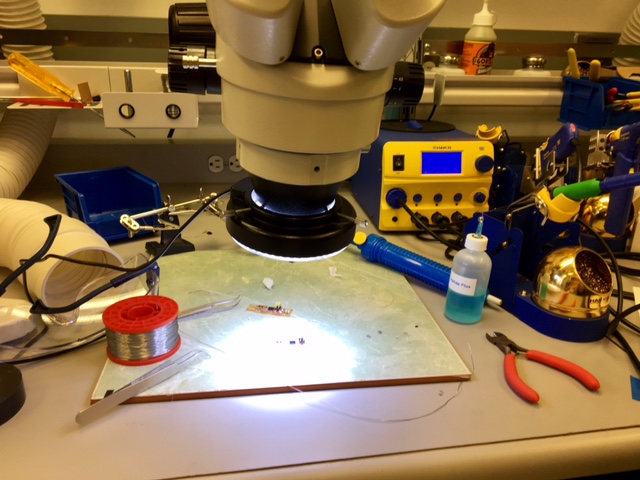
Figure 14: Soldering Workstation
Once I finished soldering (which took some time, but now I am getting the hang of it!), I was not privy to the fact that my LEDs were soldered super skewed on their solder joints.
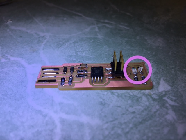
Figure 15: Bad Solder Job for the LEDs
Therefore, I had to go back and resolder those two components. Using the copper solder stripper and some dexterity, I finally came to the following board layout, which looks pretty great!
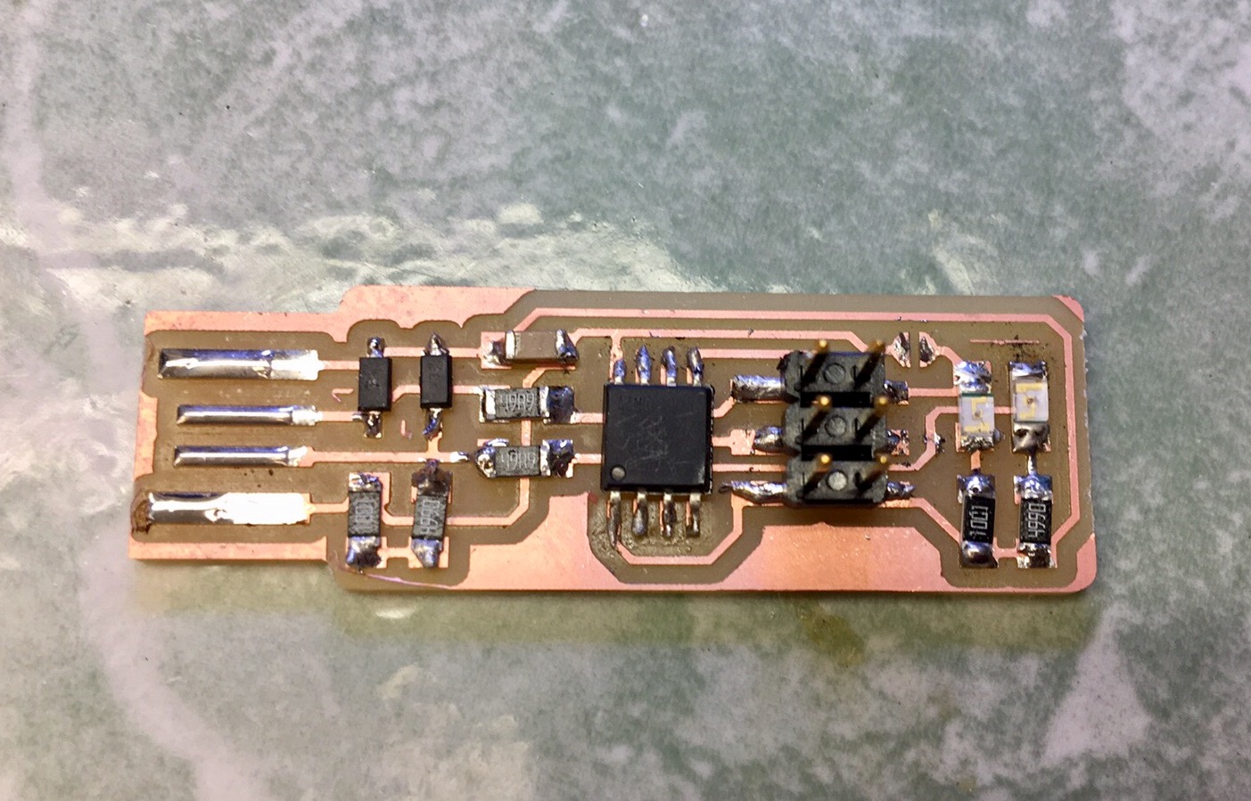
Figure 16: A Finished Board, yay!
I checked the solder joint connects and trace connections once again with a multimeter, and it looks like the board is just about read to be programmed!
Stay tuned for more progress on "Programming the Programmer" to come!
UPDATE!
After a few weeks, I retried my luck at creating a programmer from a programmer, and after some initial help testing the solder joints and making sure all the components were connected properly and in the correct orientations, I was then able to get started with the actual programming.
But first, here is the PCB with the "bridged" jumper, which is required to close the circuit, and have the board be programmed.
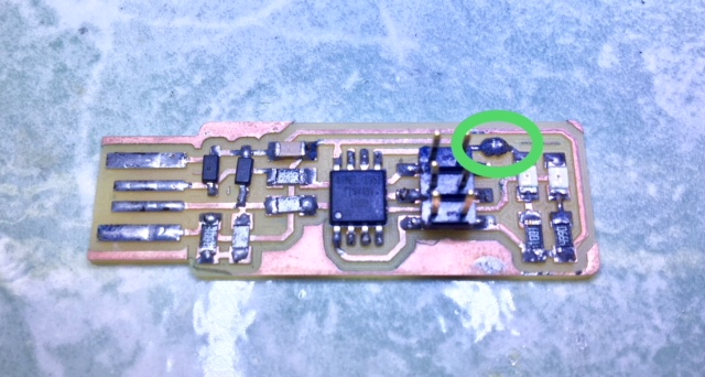
Figure 17: Jumper Connected with Solder
To get started with actually "programming" the soon-to-be programmer, I followed the instructions on former HTMAA participant, Brian's page in order to download CrossPack for Mac OSx, that includes the necessary AVR libraries required for sending the correct commands to the programmer to my board.
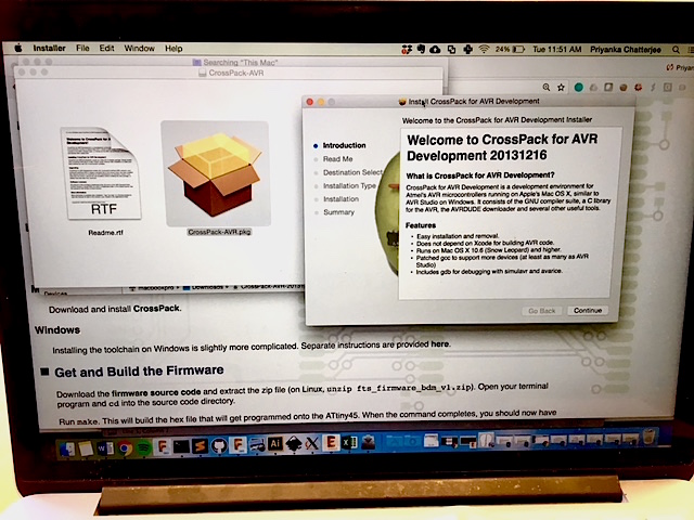
Figure 18: Installing CrossPack AVR Development Tools to Start Coding in this Environment!
Once the installation was complete and successful, the overview of the Crosspack package for AVR development cam up, and since we will be using an ATTiny45 microcontroller to program my own ATTiny 45 microcontroller on my board, I made sure teh assembler supported this device, which it does!
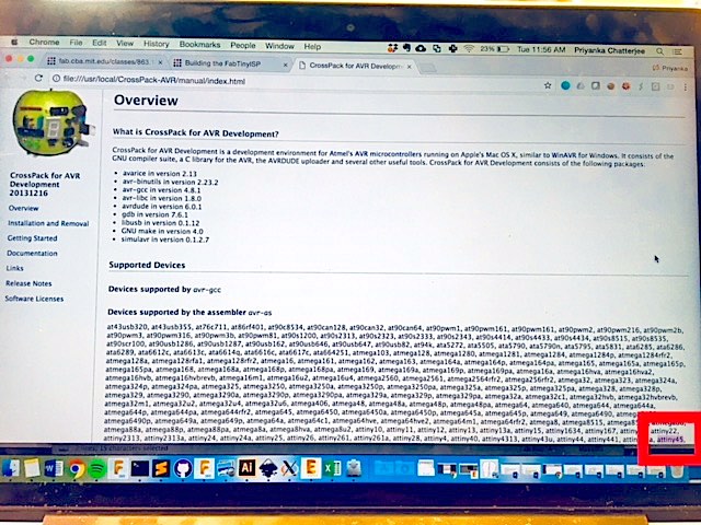
Figure 19: Indeed CrossPack Works for the ATTiny 45!
I then downloaded the firmware source code and unzipped the zip file that includes the MakeFile that we will be using to program my board. Here is the picture of the MakeFile from my Downloads directory.
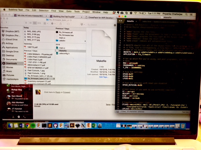
Figure 20: Downloading the MakeFile
But first! Before actually running commands using the MakeFile, I needed to acquire an already programmed programmer so that it can then program my own board into a programmer. EDS luckly had an ATTiny45 USB programer in-house, so I didn't have to make any changes to the MakeFile. Hooray! I then connected it to my board (making sure the soldered leads touched the metal leads inside the USB housing) and then connected the system to my computer via a USB extension chord. Below are pictures of the in-house programmer that I used to program my board. As well as the whole setup.
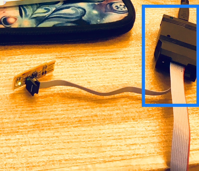
Figure 21: Using an Existing Programmer (boxed in Blue) to Program my Board
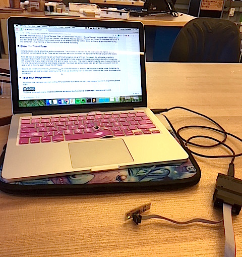
Figure 22: My Whole Setup
Once I connected my board via the black box ATTiny45 programmer to my computer, the green LED turned on! (The instructions said it should have been a red LED, but I accidentally switched the positions of the two (red and green) LEDS. But that's ok! Because the LEDs here are only indication markers. Here below is my lit up green board ready to be programmed!
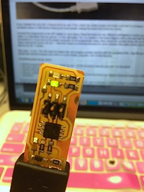
Figure 23: Green LED is ON!
Now that my board is connected and my computer recognizes the black box ATTiny45 programmer, I followed the insturctions on Brian's webpage and opened my terminal program, cd'd into the source code directory, ran "make" in terminal (which recognized the programmer), ran the "make flash" command in terminal to erase whatever was on my board's microncontroller and write over it flash memory using the .hex file in the directory, and then verify the chip.
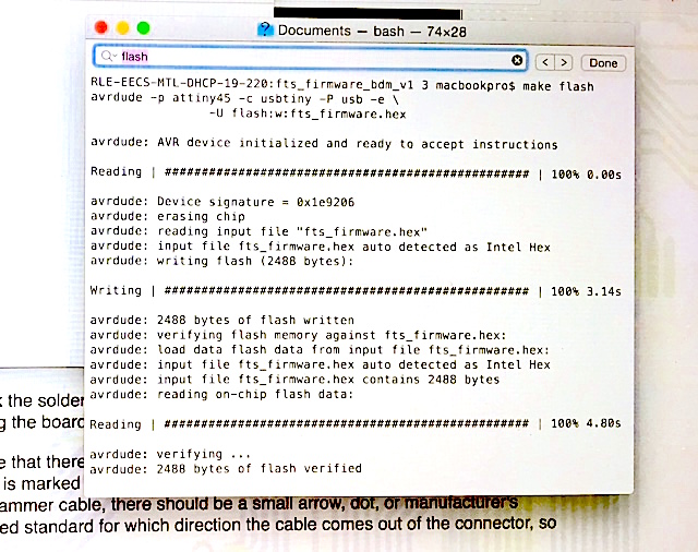
Figure 24: Going through Terminal Command Lines to Execute the Steps to Programming the Programmer
Now, to set the configuration fuses EXCEPT the one that disables the reset pin, I ran the "make fuses" command to prepare ourselves to then BLOW the fuse so then it dsiables the reset pin on my board and makes it into a programmer (and not something to be programmed). To do that I inputted "make rstdisbl" in my terminal window which then happily disabled the reset pin!
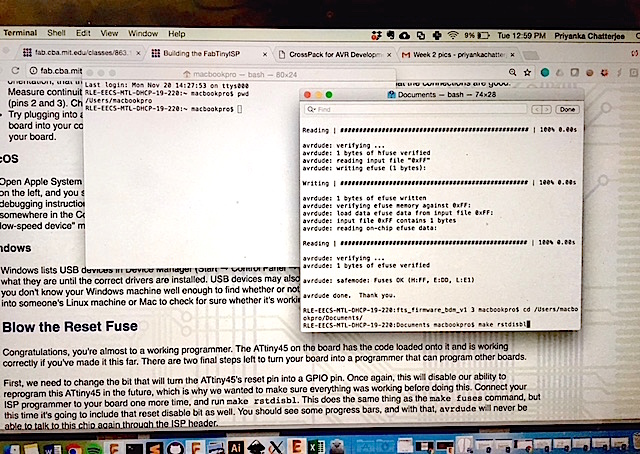
Figure 25: IT WORKED!!
Lastly, to have a working programmer, I desolder the jumper, disconnecting V_cc from the V_prog pin on the ISP header, and now I have a working ISP programmer that I can now use to program other boards that I will be making for the class!
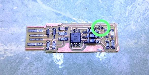
Figure 26: Ready-to-Use Programmer :D
Hooray!! I finally have a working programmer that I made myself! How empowering! More programming and electronics work to come!!