Week 9: Machine Design
"Priyanka Works Together with the EECS Crew to Learn HOW TO MAKE a Machine in a Week!"
For our Ninth Assignment for How to Make (Almost) Anything, we are doing a GROUP PROJECT (!!!) designing a 3-Axis machine that can accomplish a simple task. Perhaps a simple output, but definitely a gigantic feat for a diverse team of engineers and non-engineers in just one week to complete! Nevertheless, here we are and we have been persisting. The endeavor has been quite the bonding experience for our adorable little EECS section.
Designing the Machine: A Methodology
As a Mechanical Engineer (SB and currently in MS), I was (thankfully) put on the Design Team to create the first iterations of our design and, specifically (me personally) do the dimensioning for our 3-axis machine.
I chose to employ my knowledge from a previous (amazing, wonderful, so vital) MechE Class called Precison Machine Design taught by the one-and-only Prof. Alex Slocum last semester, and it has been extremely helpful in giving me the confidence and knowledge to know how to build a machine from concept to finished product.
In Alex Slocum's class, we learned to start off with creating a set of Strategies for the type of machine we want to build. Strategies are the very basic ideas for what we want (satisfying what we call our "Functional Requirements"). As a team, during our first meeting, settled on the "strategy" of designing a machine that could move and jog from one position to another (to create a pattern using an end effector of some sort) we decided on the Concept of a Delta Picker.
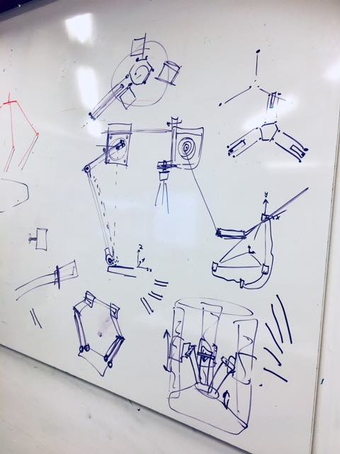
Figure 1: Various Initial Concepts to Consider
As can be seen above, with our tinkering and free-form designing, we came up with three different concept Designs including a pinion-pulley system, a double-jointed free-standing picker, and a linear rail guide system for moving arms independently to produce lateral motion. After assessing the feasibility (size, materials, complexity, etc.), physical first principles, risks, and countermeasures (as well as what can provide us with relatively enough creative license, without overt complexity), we ultimately decided upon the rail guide system, seen below.
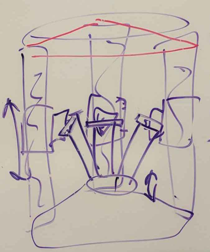
Figure 2: Rail Guide System Initial Sketch
This image above shows the very initial rough draft of our Delta Picker design concept. We settled on this chosen concept to provide us some freedom and creativity for our machine (since there are already many delta picker designs open-sourced) but to not over-complicate the system either. We were also looking for a stand-alone, portable system for convenience of build, setup, and presentation.
Here, I plan to put in a FRDPARRC Table detailing our Delta Picker Design Concept
Here below, I have initialy sketched out the system comprised of three upright linear rail guides, its braces, top and bottom plates, the carriage system with arm bearing positions marked and attachment positioning of the hinged arms for the end effector attachment at the base of the machine.
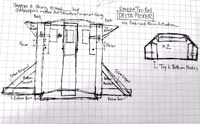
Figure 3: Initial Sketch of Our System
I then went ahead and made some rough sketching of what the carriage system may look like with a stepper motors attached -- similar to the machine that we were able to see demo-ed by our TA Jake Read. I sketched out the linearly actuated carriage system that includes attachments for the stepper motor, bearing blocks for the arms, and the base attachment for the end effector (sizing not to scale).
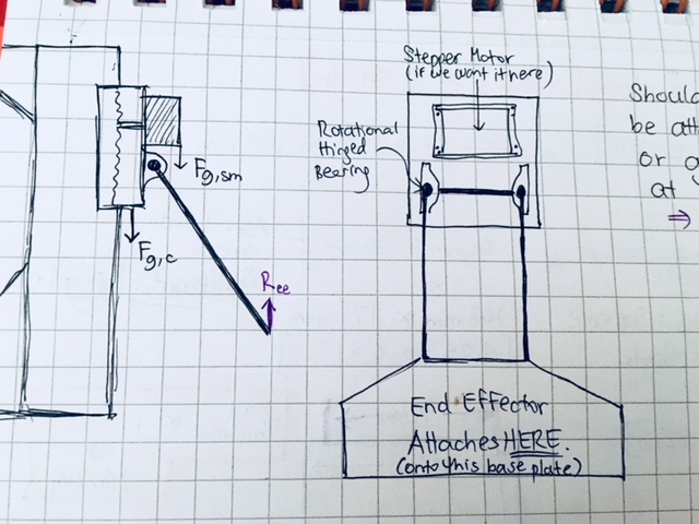
Figure 4: Potential Carriage System Design
Next, I started with the dimensioning of our parts. Form my knowledge from Alex Slocum's class, I have been well-versed in using St. Venant's Principle and the Golden Ratio for initial sizing of parts to maintain structural rigidity, minimize vibrations during motion, and optimize the stress distributions to minimize strain on the system.
Since the "Most Critical Module" (Slocum speak) is the end effector for our specific concept design, we decided to size this first.
This image below shows the initial sizing of the end effector plate which we chose (due to bedside constraints and functional requirement of portability to be approximately a 4 x 4 inch planar size. We plan for this design to be replaced with the actual end effector design by that specific design team in our section. (However, in the end, a similar aspect ratio was indeed chosen for the final design.)
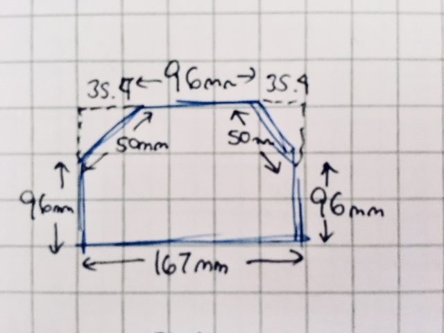
Figure 5: Initial End Effector Plate
Now that we have a rough sizing of the end effector, we can move to sizing the rest of the machine components, including the arms that are hinged on bearing blocks that will change angle when moving on the linear guide rails up and down to change the planar distance of the end effector plate.
In order to size the arms, we will also need to know the frame sizing. Using simple Pythagorean theorem and the rail lengths (based on sizing feasibility estimates) and end effector width decided previously, we can calculate the maximum arm length for moving an end effector of an approximate 4 x 4 inch planar size within the x-y plane of the machine workspace.
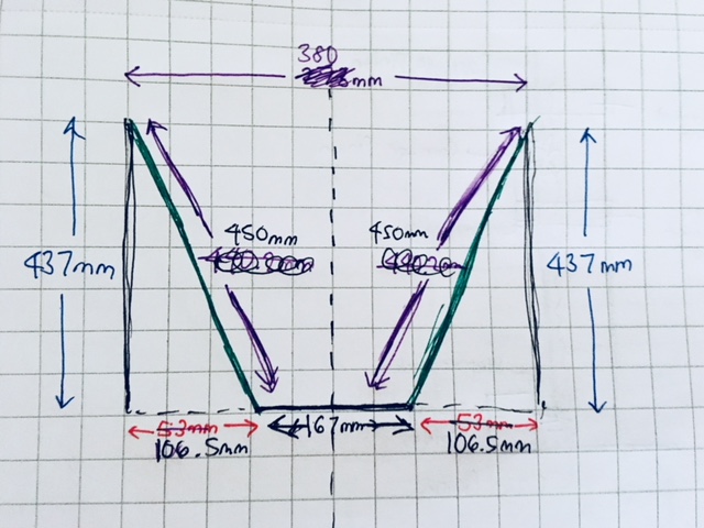
Figure 6: Sizibgn of Arms & Frame
The sizing of the arms was dimensioned to accommodate for the rail sizing/length for vertical distance required for the carriage to move, and the reasonable workspace we wanted for the machine as a whole.
Actually the arm lengths specify the MAXIMUM length of the arms for our initial design, and could work with a shorter arm, (though the end effector would be then elevated higher than the bottom of the machine).
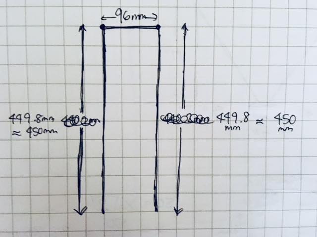
Figure 7: Sizing the Hinged Arms
Now that we know the general frame and arm dimensions, we can figure out our full workspace and thus rail spacing. This image below shows the top down view of the spacing of the rails with respect to each other in the x-y plane. These spacing measurements were calculated based on the sizing of the end effector plate and the lengths of the arms required to move the end effector along the planar workspace (via the linear actuation of the arms along their vertical rails).
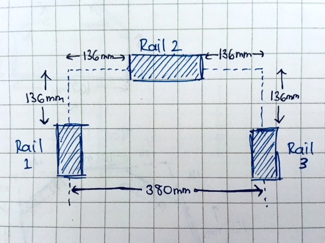
Figure 8: Spacing the Rails Appropriately
Now, it is possible to dimension the top and bottom frame plates, based on the rail orientations, sizing, and positioning.
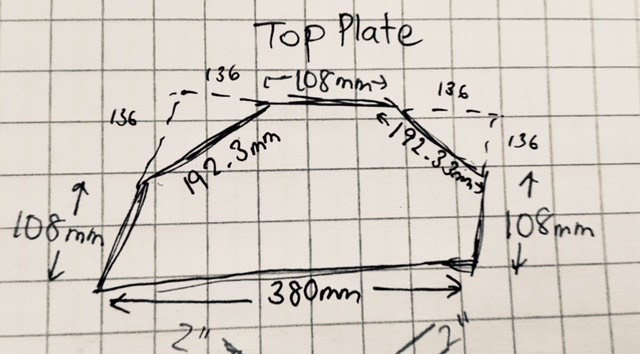
Figure 9: Top & Bottom Frame Plate Sizings
Next, I sketched out the layout for the rail, carriage, and attachments for the stepper motor and arm (per rail). The dimensions were determined based on the given dimensions of the stepper motors that we are to be using for the design. (Even though in the picture, I mention a square aspect ratio, in the end, it turned out to actually have rectangular dimensioning).
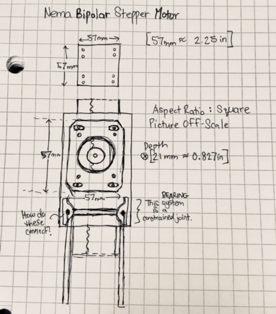
Figure 10: Stepper Motor Carriage Attachment Design
Finally, I dimensioned for our initial design of the carriage system that would be attached to the geared rack and pinion system. The dimensions were sized to provide enough room and support for the stepper motor and its attachment plates, in addition to accommodate for the appropriate sizing of the guide rail. The aspect ratio for all the parts was determined from the St. Venant Principle and the Golden Rectangle ratio of 1:1.6.
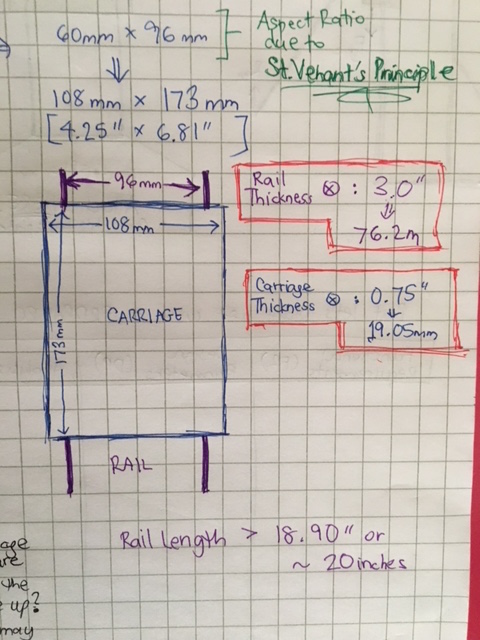
Figure 11: Dimensioning the Carriage & Rail Thicknesses
CRUNCH TIME!!
On our last day, I also helped out with the milling of the parts and the assembly and build. It was quite stressful staying up all night, but (hopefully) rewarding in the end.
That evening, I helped monitor and input the feeds and speeds for the milling of the HDPE linear guide rails on the ShopBot Buddy machine in the Architecture design studio. Here below is a picture of the rails being milled out and then cut from the bigger piece of HDPE.
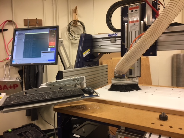
Figure 12: The ShopBot Buddy at Work!
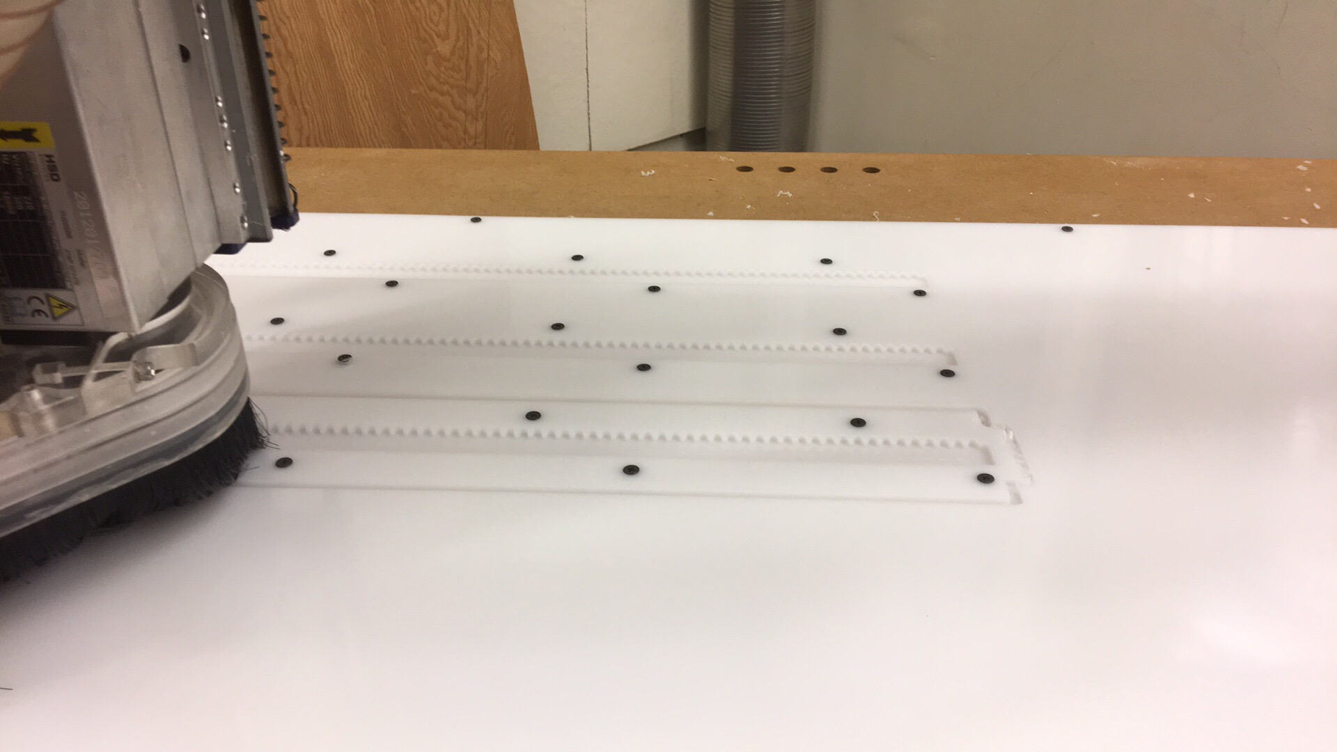
Figure 13: The Rails Being Milled
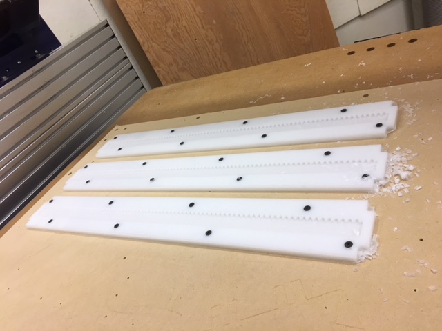
Figure 14: Rails Fully Milled on ShopBot Buddy!
Finally, I stayed up with the team to troubleshoot and assemble the machine together. Here are some pictures from our trials and tribulations (and ultimately triumphs!)
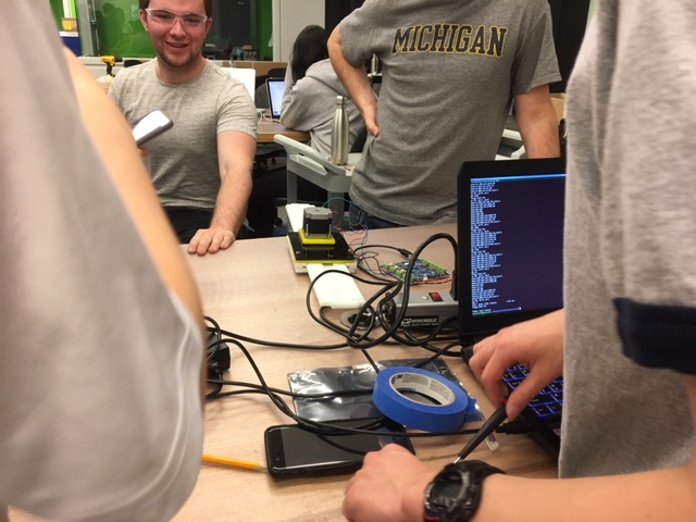
Figure 15: Watching while Ben Troubleshoots the Connections
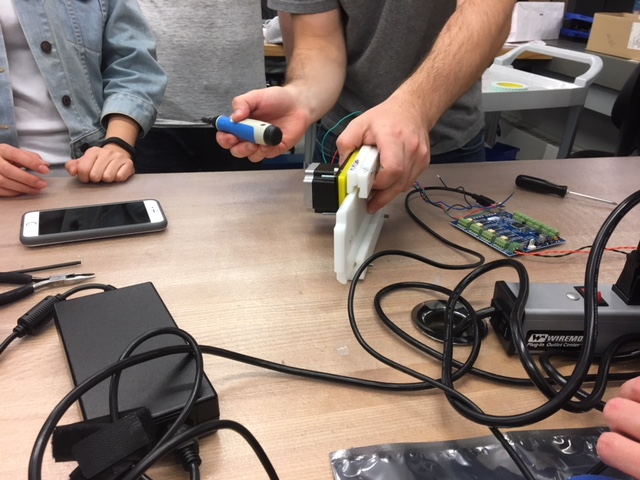
Figure 17: Troubleshooting the Hardware - CAVEMAN STYLE
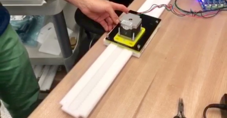
Figure 18: Screenshot of our Rack and Pinion Rails Moving Via our Stepper Motors - LAYING FLAT
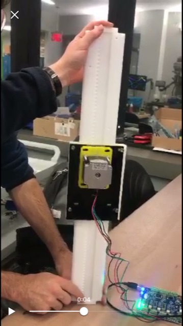
Figure 19: Screenshot of our Rack and Pinion Rails Moving Via our Stepper Motors - UPRIGHT
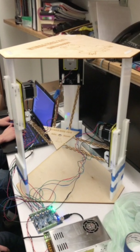
Figure 20: Our Final Machine!
Kudos to the whole team, without which we could not have made it this far! Go team!! :D