week 2: electronics production
This week's assignment was to make an in-circuit programmer by milling the PCB and soldering components. I followed Brian's instructions to build the FabTinyISP. Before this week I didn't even know what a PCB was or how to spell solder, so I learned a lot of new skills.
The week began with training on how to machine the board and how to solder. I had never soldered, so practicing on the breadboard was my first experience soldering.
Learning to solder with resistors on a breadboard.
When I went to studio to mill my board, another student, Nikki, was in the process of milling hers. The left side of her PCB looked perfect, but the traces on the right side weren't fully cut out. With help from Dave, we lowered the endmill and redid the traces from the same origin, and it fixed the right side. It seemed like we sorted through the problems on Nikki's board, because when I went to trace and cut mine, it worked on the first try.
Cutting the traces (left) and cutting the outline (right).
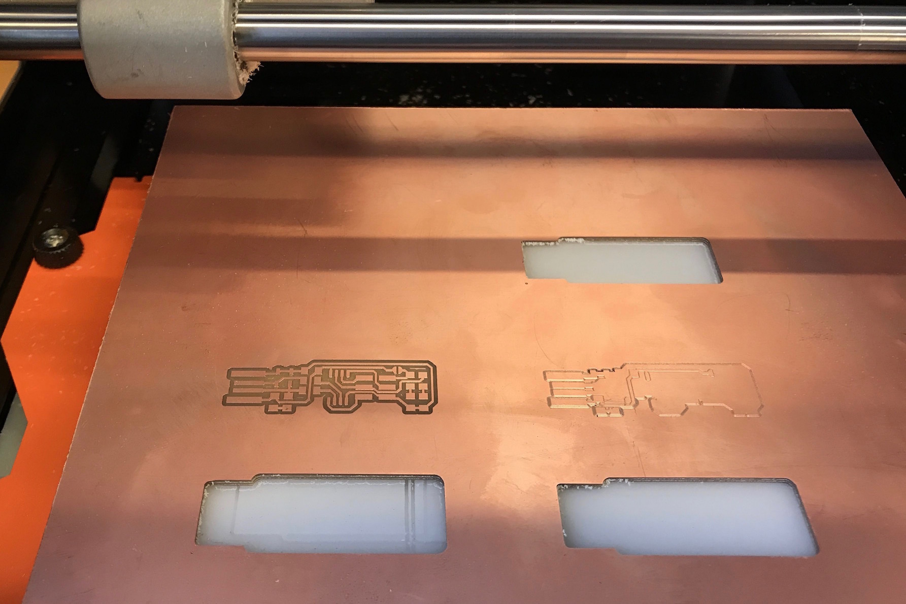
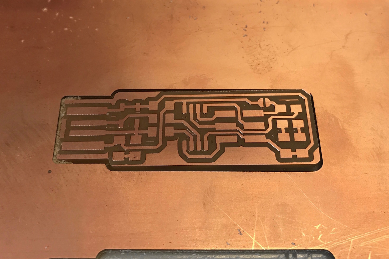
I cut the traces and the outline for my board with no problems.
I shaved off the copper on the tip, and then started soldering components, beginning with the ATtiny45. Another shoutout to Dave from EDS who showed me the back room with the precision soldering irons and gave me tips to help me get started soldering my board. After soldering spread out over a couple of days, I had assembled my PCB. I learned that tape, tweezers, and solder wick are quite useful tools for assembling the board. I struggled with getting smooth layers of solder, because I kept getting pointed tips from when I pulled away the iron, but I did improve throughout the course of attaching all the components. And I was able to get the four USB contacts to be smooth layers of solder.
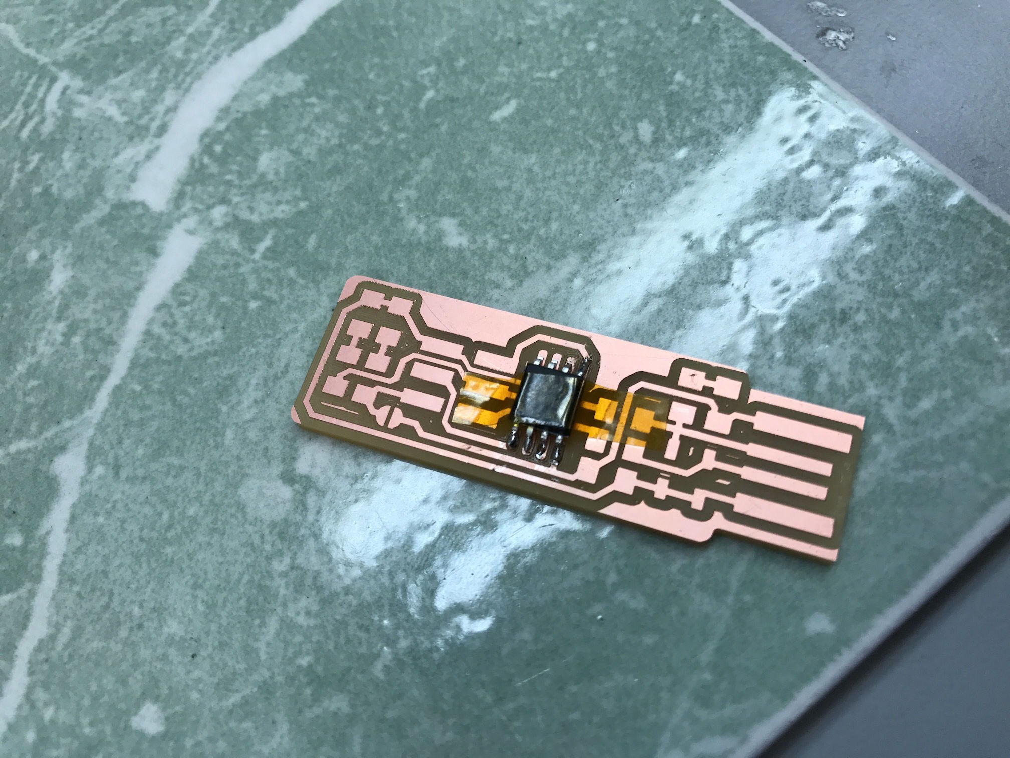
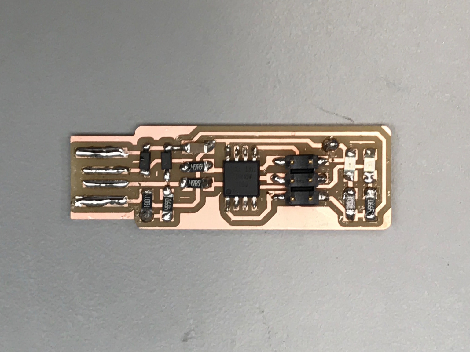
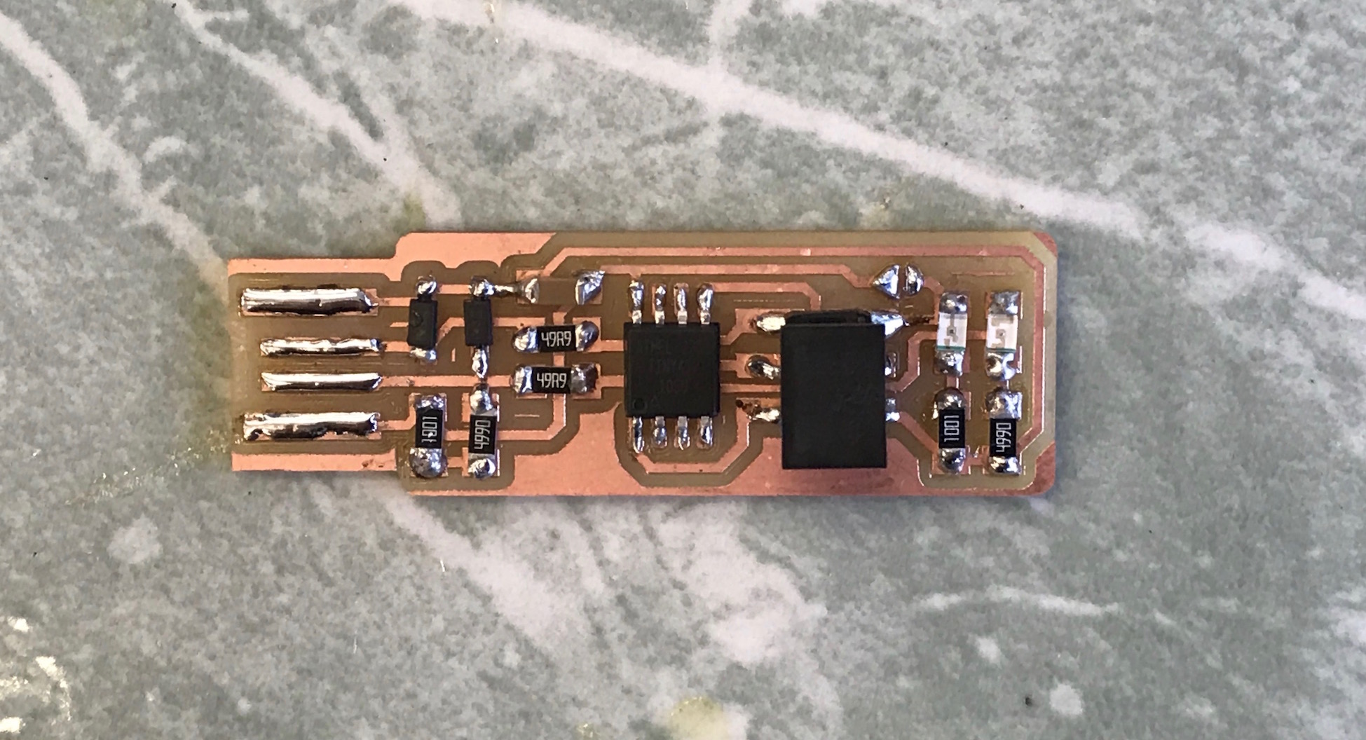
My PCB early on in the assembly process (left), and after I had finished soldering all the components (right).
Once I finished the soldering, I installed CrossPack and successfully built the firmware hex file (once I made the delayed realization that I needed to restart Terminal). I connected my board into the USB 2.0 connector and was excited by the fact that my red LED lit up.
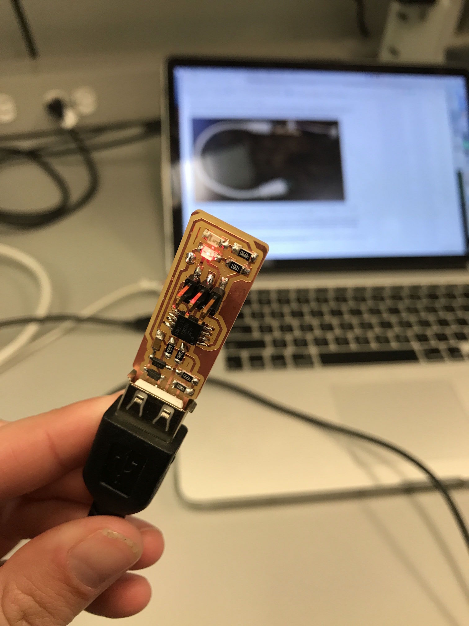
I've never been so excited about a red light before.
I ran make flash to program my board, and it worked. Then I tried to test the USB functionality and became stumped as to why the device wasn't being recognized. On Linux, I logged the messages and saw that a new low-device USB was being read, but errors were occurring because the device was not responding to the setup address. I stopped working, and when I came back a day or two later to try to debug my board, I realized I was terrible at following directions. I'd never ran the command make fuses to set the configuration fuses. Once I did that, I connected my board and it was recognized as a USB device, both on my computer and on a computer in EDS.
I had a bit of trouble trying to blow the reset fuse. I tried running make rstdisbl with my board connected both to my computer by USB and to the programmer which was connected to my computer, and kept getting the same error. After asking for help, I ran the command with my board only connected to my computer via the programmer, and it worked. I then used the soldering iron one last time to remove the bridge on the jumper. I have not yet tested using my board to program another board, but I believe I made a working ISP programmer!
My finished ISP programmer!