week 6: embedded programming
This week, our assignment was to read a microcontroller data sheet and program our board from the electronics design week to do something, using as many programming languages and environments as possible.
I tried to start this assignment early, because I knew I'd be traveling from Saturday through Tuesday and lose most of my normal worktime. I started where I left of two weeks ago during electronics design week. I had designed milled, and stuffed my board, but not yet programmed it. I connected my programmer from electronics production week and my hello world board, and...nothing worked. My programmer was no longer recognized as a USB device by my computer, even though it was recognized two weeks ago. I swapped out my programmer for one of the USBtinyISP AVR programmers from EDS. Now, the USB device was recognized by my computer. I referred here for guidance on how to program my echo hello world board. I was able to make the hex file, but but kept getting an error when I tried the program-usbtiny-fuses command.
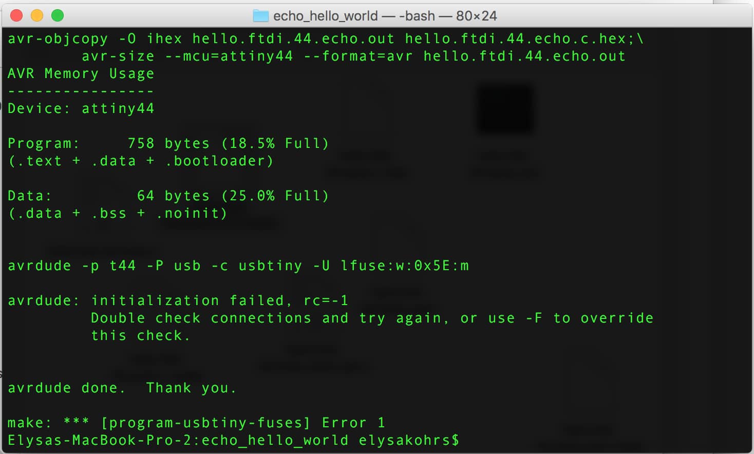
I couldn't run the
program-usbtiny-fuses command.
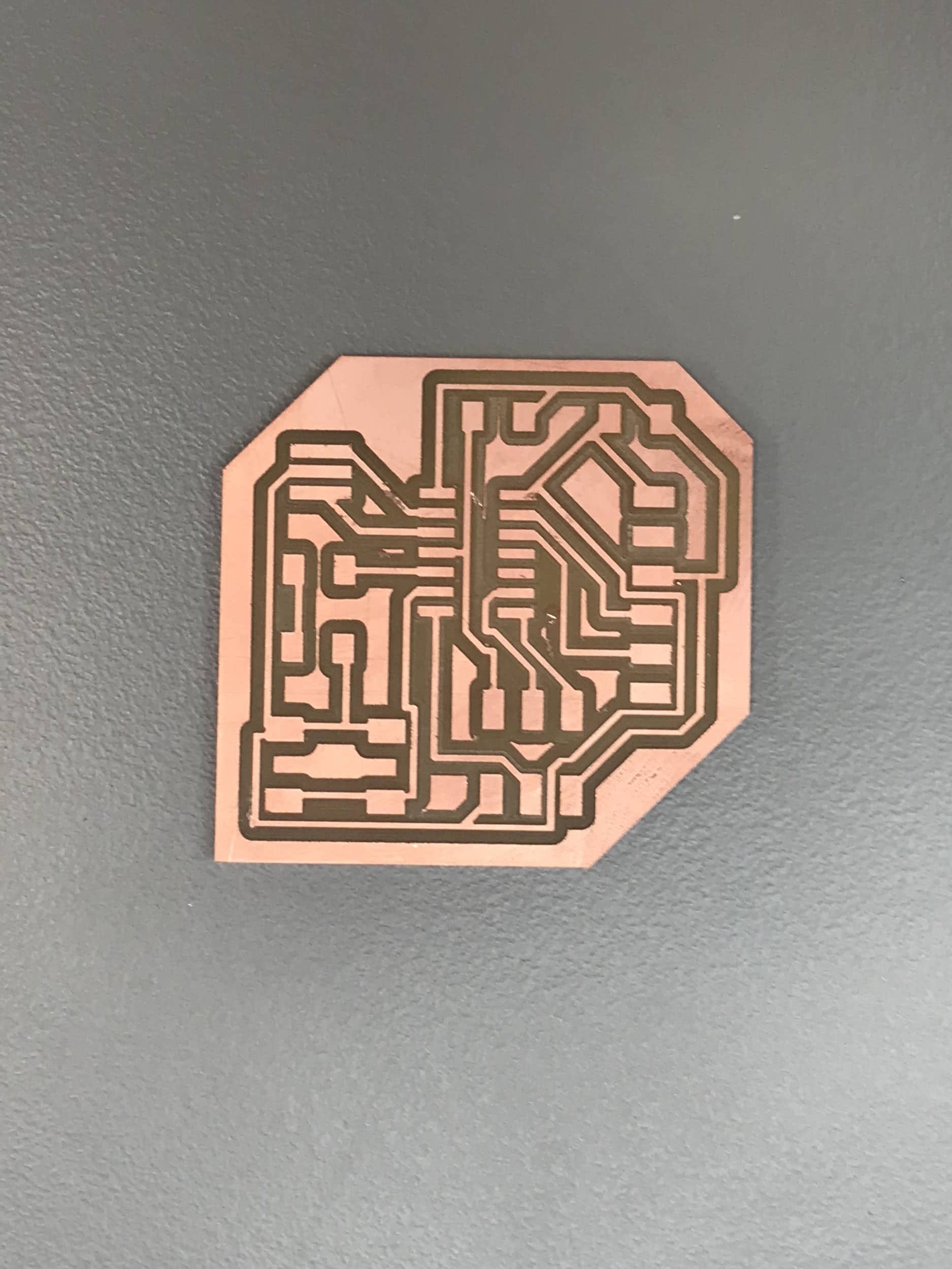
I thought perhaps there was a problem with how I connected my board to the programmer and to the computer, so I switched around the orientation of the FTDI cable and the connector for the ISP header, and tried the command again. I'm pretty sure in doing this I fried the microcontroller, because the ATTiny got really hot. So anyways, I figured that initially there was a problem with my board or soldering, but now I'd fried the microcontroller, so I wanted to start over and remake the board. But I was still curious about what was wrong with my board, so I began probing with the multimeter. I noticed that there was a short between GND and RST on my ISP header. I pulled up the PNG of traces for my board and photos of the board before I stuffed it, and I noticed that even though my file was correct and showed the two pins not being connected, the actual board had them connected.
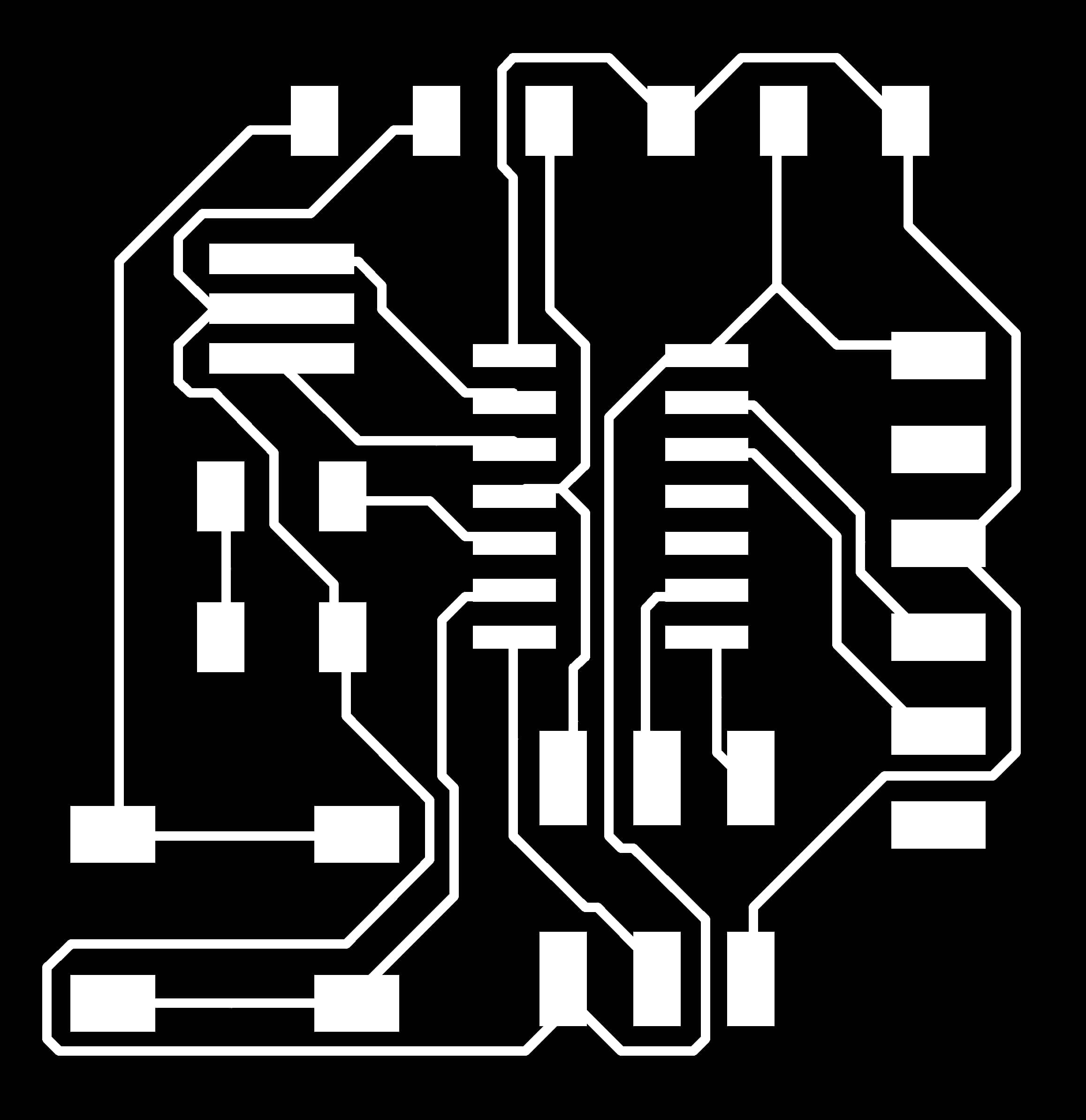
The file I used to cut the traces for my old board was correct, but on the physical board, the traces running under the microcontroller were not separated.
I'm not sure what caused the traces of my final board from week 4 to be incorrect, given that my board design seemed correct. So I decided to play it safe. I went back to Eagle and spaced out my components a bit further to give more room for routing. I also added space for the FTDI header to rest on the board since my initial design didn't allow for that. And I removed the resistor that was connected to my switch since I realized we can use the internal resistor. After making minor changes and rerouting, I had this design.
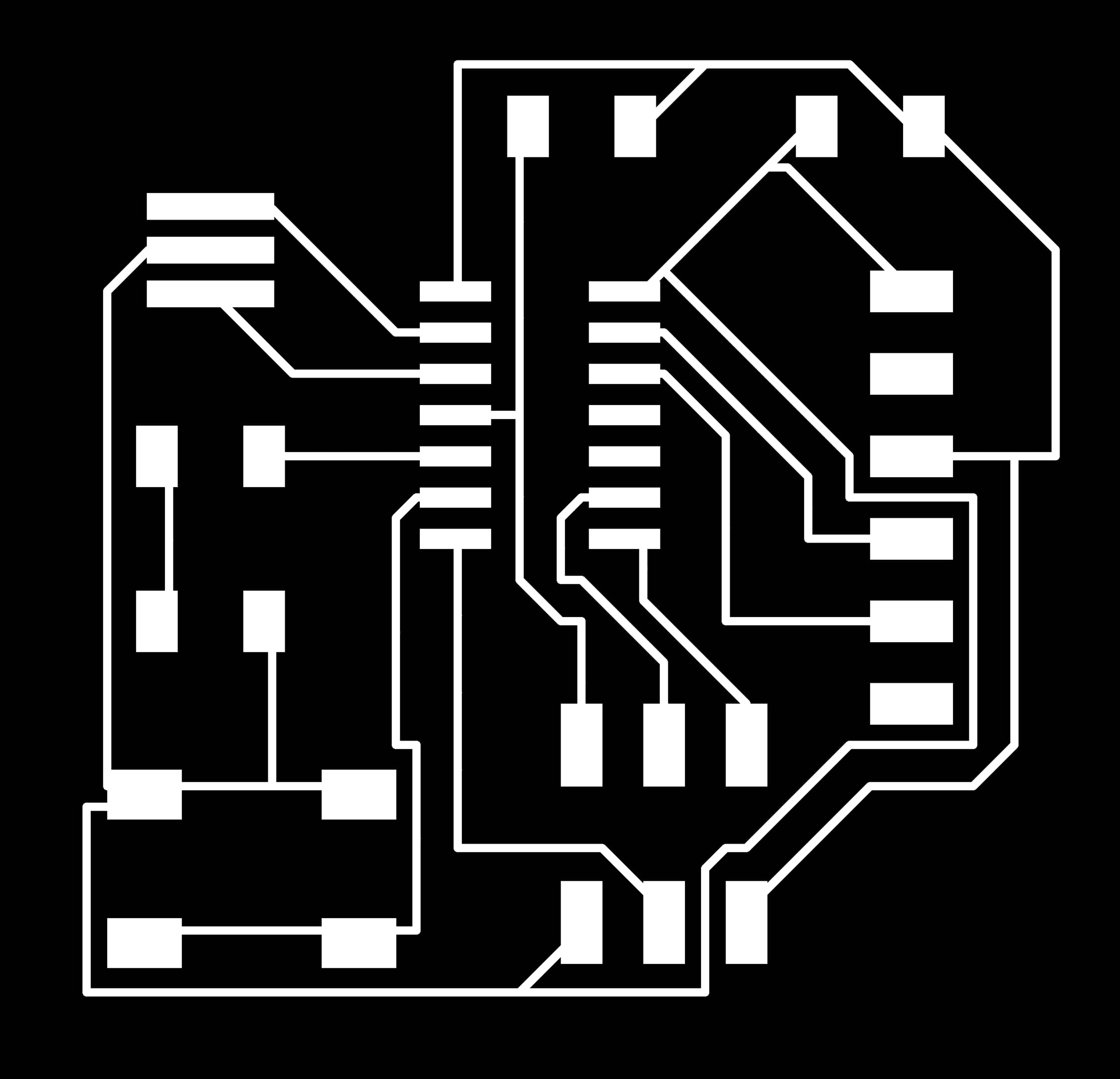

The new traces and outline for my board after slight modification.
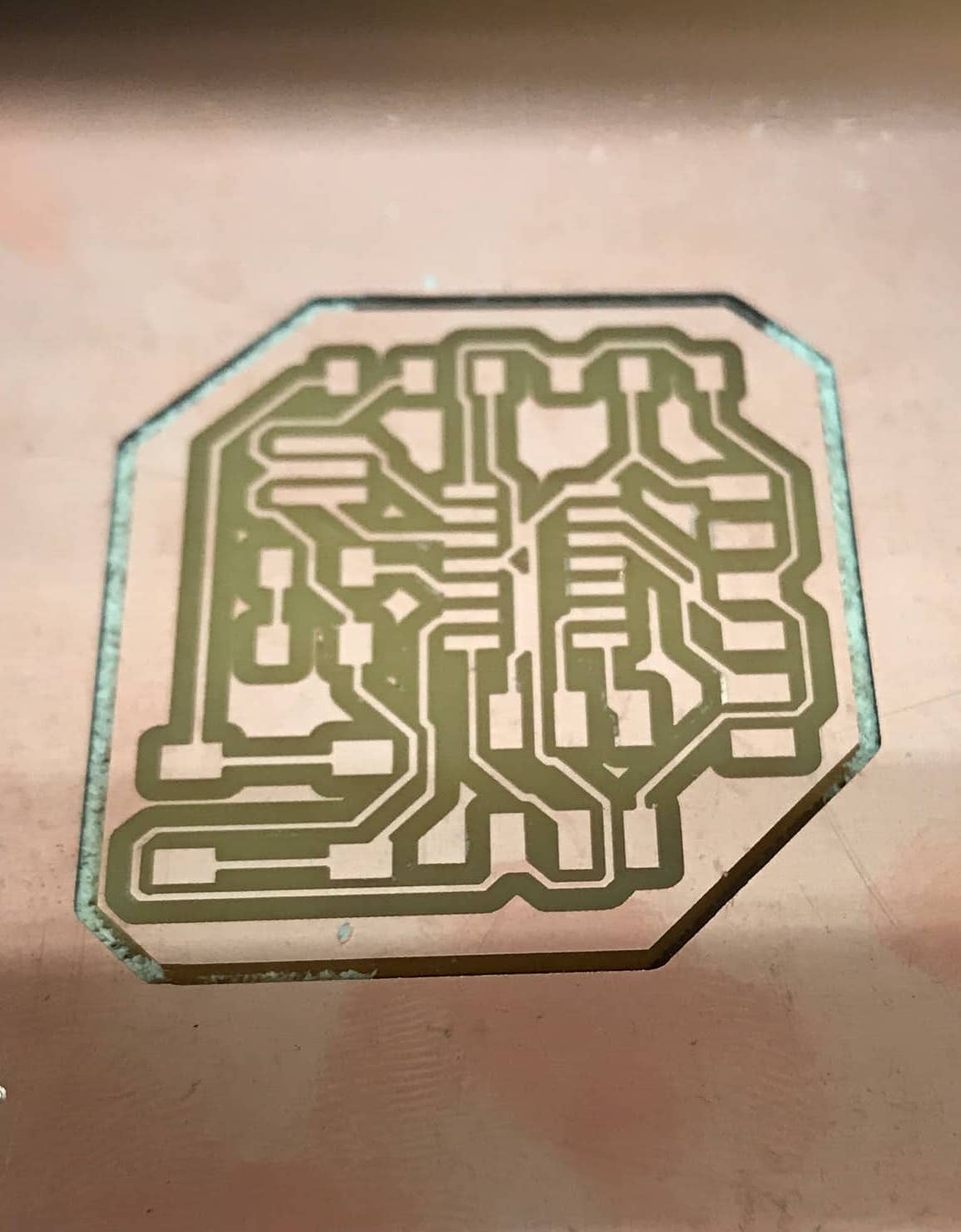
Milling the board went smoothly. I checked that the traces that were mistakenly connected in my last board were separated and then gathered all the parts to solder. My soldering is continuing to improve, and I actually find it very cathartic now. The 1 µf capacitors were missing from EDS while I was stuffing my board, so Dave helped me use the soldering gun (I think that's what it was?) to release the capacitor from my old board, so that I could attach it to my new board. Soon after I finished all the soldering, the missing bag of capacitors was discovered.
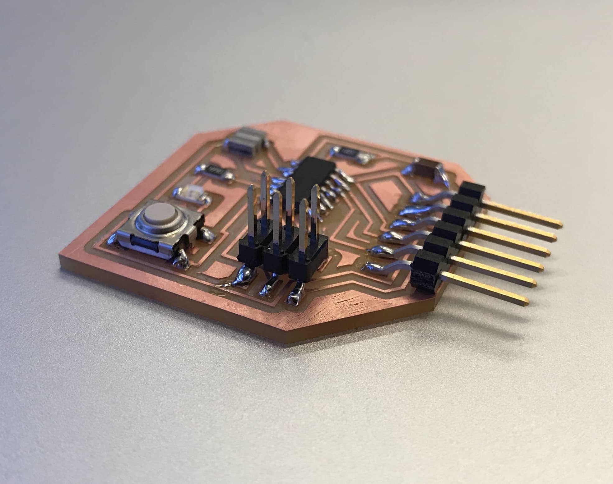
My new board after milling and soldering.
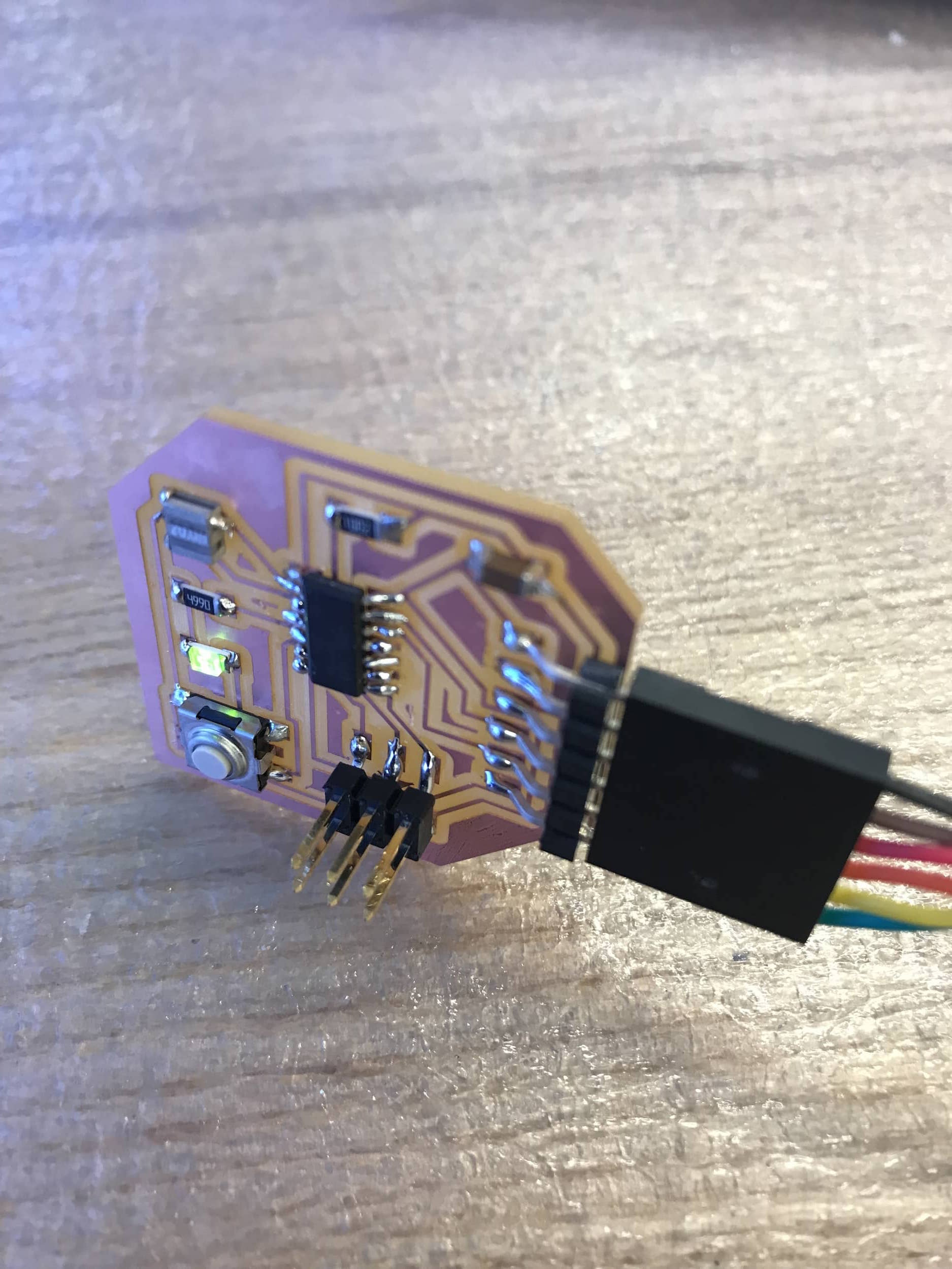
I connected my new board to the programmer and to my computer, and tried tunning the same program-usbtiny-fuses command that kept failing before. And it worked! And the next command, program-usbtiny was also successful. I tried typing the next command, which was python term.py /dev/ttyUSB0 115200. It failed, but I was expecting it to, since I hadn't downloaded anything called term.py and didn't really know what that was supposed to do. Alexandre happened to be in EDS at this same time, and I asked him for help since he'd already programmed his board from two weeks ago. He recommended that I try screen to test the echo hello world program. We found the path to the connected USB device, and then in terminal were able to see the output from the device. And like it was supposed to, it replayed back everything you typed. The line breaks were off, which might just be a problem with using screen.
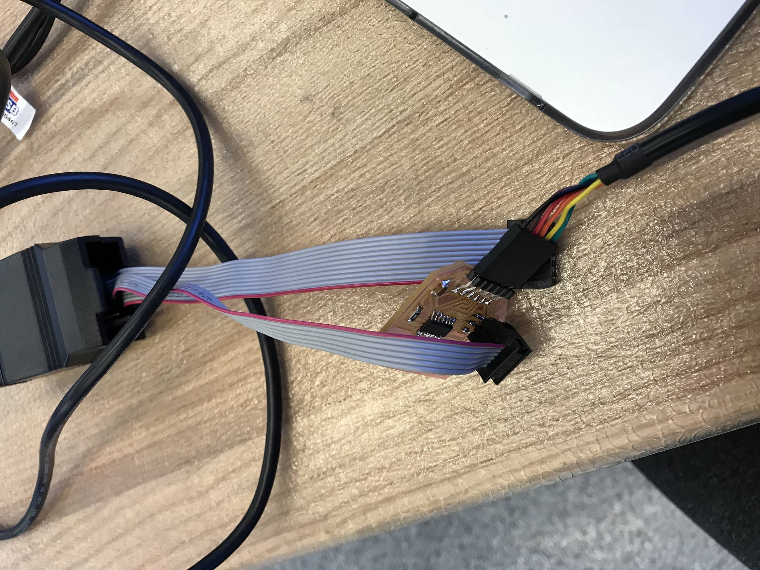
Connecting my computer, the programmer, and the new board.
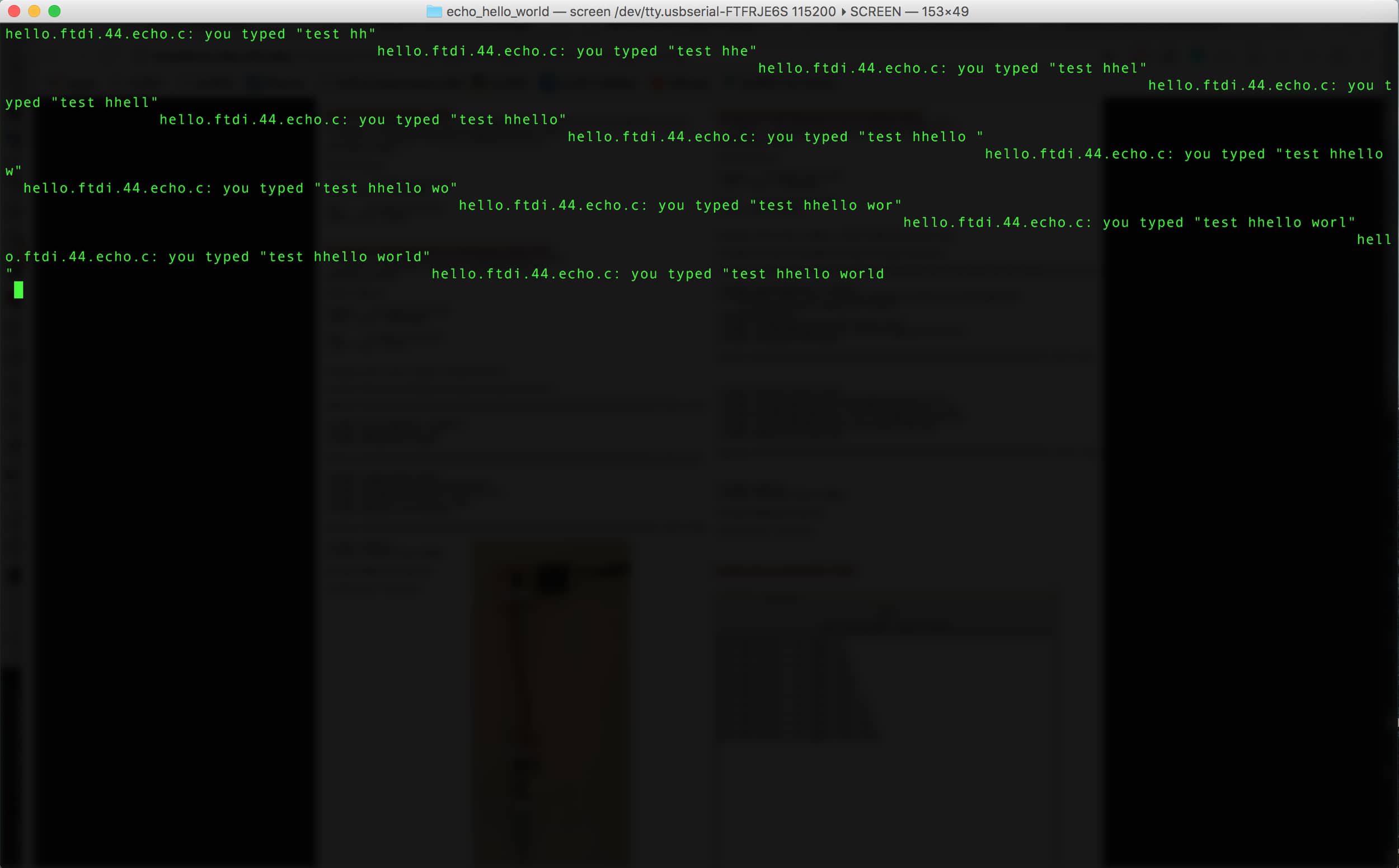
My board echoes correctly, the indentation was just off with
screen.
I wanted to make my board do something else, so I wanted to write a program to cause pressing the button to light up the LED. I referred here and here, and came up with a program that I thought would make my board behave how I wanted. It didn't exactly work. The LED stayed on almost always, and would randomly flicker off, but it was completely unrelated to pushing the button.
The LED stays on instead of responding to the button press.
Later on, I got help from fellow EECS student Ben and he helped me debug my program and in general helped me become a little more comfortable with embedded programming (thanks so much Ben!). One of the problems we discovered with the blink program I had was that I wasn't setting the internal pull-up resistor for the button. After a couple other changes and setting the pull-up resistor, the LED on my board turns on and off when the button is pressed! The file with the code I used is here.
I had been using the C code until now, and I wanted to try using Arduino to program my board. I downloaded the Arduino software and referred to this guide for help on how to use Arduino to program an ATTiny. I added the necessary board managers and changed the board and processor to be accurate. I modified a simple blink script, and uploaded it. However, it didn't work. Still have to figure this out.