I began the week by practicing my soldering with resistors on a bread board.

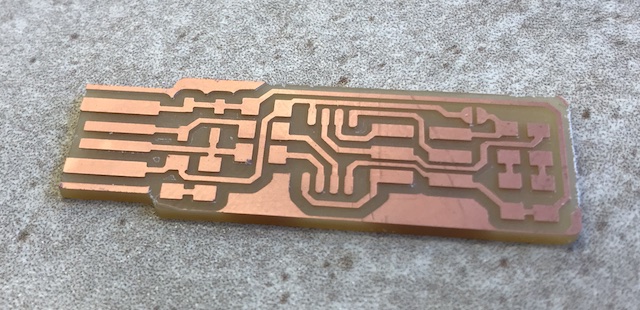
After practicing soldering, I proceeded to milling out my printed circuit board (PCB), which was accomplished after some short difficulty communicating between the computer and CNC Mill (SRM-20). Here we used class-made (Neil-made? Thanks!) software to direct the mill where to cut. First, I etched the traces and then cut out the chip from the rest of the board. My PCB actually ran into a previous cut made out of the same copper + laminant. This was actually a boon as you will see in the picture below as I did not have to remove any excess copper from the top of the USB connection.
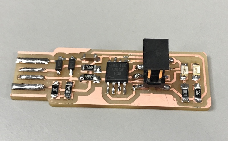
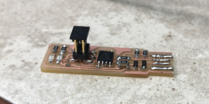
And with that, I began soldering the surface mounted parts onto the PCB. The surface mount parts were almost a completely different process than the soldering practice I had done on the bread board due to the sterics of the part itself. Additionally, instead of being 'locked' into the holes in the bread board, these parts could still move around before being anchored down with the first soldering. With an awesome tip from Ben (thanks Ben!), I first would lay a small glob of solder onto one of the pads without the part in place. With the solder already in place, I could hold the part with tweezers in one hand and the iron in the other to anchor the part down, without having to worry about my lack of a third hand to introduce solder. After the first anchor was down, I was able to solder any additional pieces quite easily and could clean up the initial soldering as needed. With all my pieces down, I attempted to plug my PCB into the USB connection, but the red LED would not remain illuminated because the USB connection was too loose. Following instructions on the site and with additional help from Ben (thanks!), I used solder to build the height of the USB connection until the red LED was solidly illuminated. The finished product can be seen below.
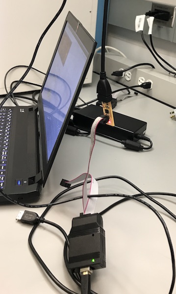
I proceeded to then use the Linux machine in the lab to program my programmer! I was able run through all of the commands successfully :)
After this success, I removed the solder junction to complete the transition of my PCB to a verified programmer.
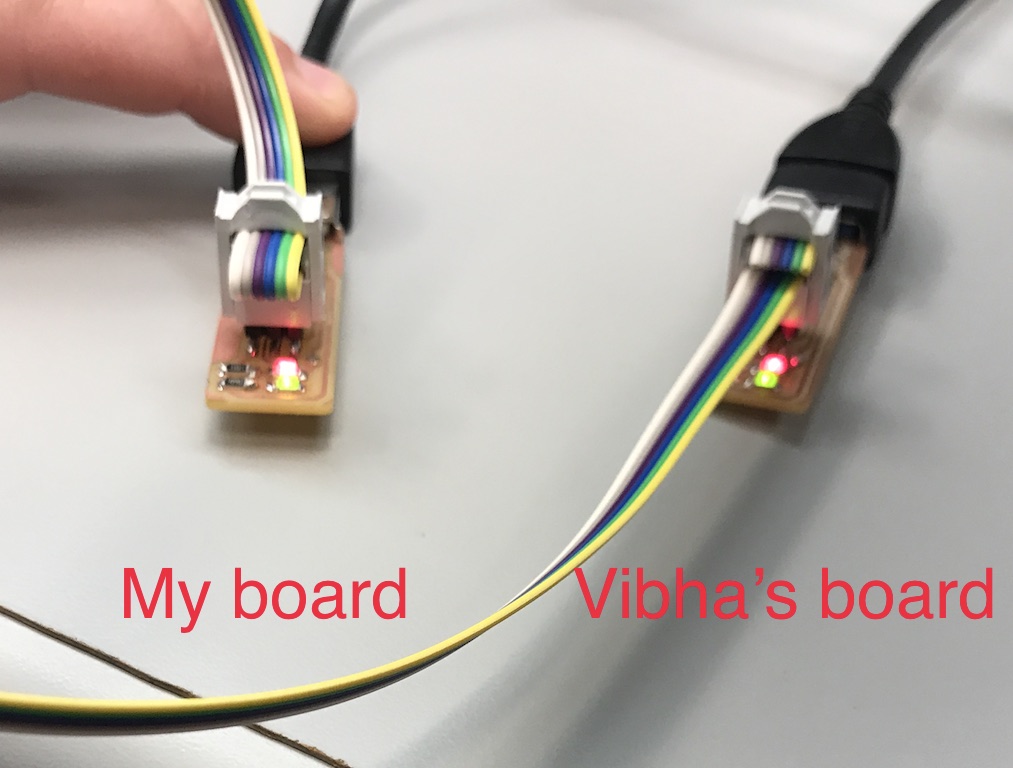
Finally, I used my programmer to program a colleague's board! Thanks Vibha!