Final Output:


Final Project Overview:
What does it do?
It is a Persistence of Vision Fidget Spinner that is able to sense the magnetic field from a magnet embedded within the bearing cap, and change LEDs based on that magnetic field value. THe final demo program stored the hall-effect value on power-on as a reference and turned the LEDs on / off depending on whether the field got stronger or weaker. The goal was to be able to use this to display letters and any arbitrary picture using the LEDs when spun.
Who's done what beforehand?
POV fidget spinner isn't as novel as I thought when I thought of the idea with a friend. There are LED fidget spinners on Amazon, and people who have done similar things on Instructables and on hackster.io. Some of the examples I found didn't have the LEDs multiplexed or charlieplexed. Some were suface-mount, some weren't. All the examples I found and were open source were written in Arduino code. Some people used shift-registers to output the LED values. Some people used a magnet and hall-effect sensor to detect orientation. I'm not sure how (or if) the others did it.
What did you design?
I designed the custom-shaped fidget-spinner embedded PCB, the 3D printed case, and all the code that I wrote.
What materials and components were used?
I used 8 clear orange LEDs, 1 hall effect sensor, 1 ATTiny44, 1 6-pin ISP header, 5 resistors, 1 capacitor, 1 20MHz resonator, and a 3V coin batter and holder. I also used one whole PCB sheet of double sided copper trace, 1 608 bearing, and filiment from the Stratasys.
Where did they come from?
Most of the components came stright from the fablab inventory including the LEDs, ATTiny, resistors, resonator, capacitor, resonator, PCB sheet, 3D printer filament, and battery. The only thing I had / bought was the 608 bearing. I beieve the fablab inventory was bought off of Digikey (at least the last stock run before final projects), but it's possible they were bought at a larget wholesaler before the class. I bought the bearing in a 10 pack off Amazon.
How much did they cost?
About $7 alltogether:

Final Project Log:
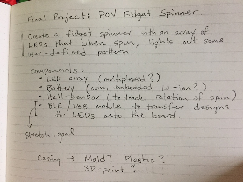
After many weeks of completing one-off projects for the weeks assignment, I came to re-evaluate what would be realistically possible for me to complete by the end of the term. What I came up with is different than all of my above brainstormed ideas (I'll save those until IAP when I have more time to work). The end project I'm working towards is going to be a persistance of vision fidget spinner.
The concept: The idea is to embed an array of LEDs in a circuit board that is in the shape of a fidget spinner. When spun, the array of LEDs would light up at certain intervals when making one revolution around the fidget spinner. With a persistence of vision effect, one would be able to almost draw shapes or text using light and the inherently fast rotation speed of a fidget spinner.
Execution: To accurately could when full rotations are reached, I think the easist and most clever way to do it would be to embed a small magnet in the cap of the center bearing cap, and then place a hall-effect sensor on the circuit board near the bearing. Therefore, when the sensor passes by the stationary magnet and has the strongest magnetic field, we will know that this corresponds to a certain orientation of the LED array relative to the bearing cap.
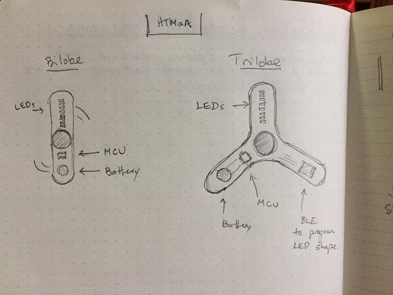
The first stage (deliverable) of this final project is to successfully get LEDs to react to a hall-effect sensor. This involves designing a board that combines LEDs and a hall-effect sensor, and additionally has the bearing and bearing cap with an embedded magnet. To break this first deliverable down, I'll start by just making a board that can detect magnetic fields and respond via serial or an indicator LED. Similarly, making another board with an array of LEDs in the shape of a bilobe fidget spinner with a coin battery would be another individual component to test. Putting these two boards together would get me pretty close to the first stage deliverable with the additional work of making the bearing caps and integrating the hall-effect sensor code with the LED array code.
These two subcomponent boards are exactly what I did as my individual input and output device projects. During the output device week, I created an LED array board:
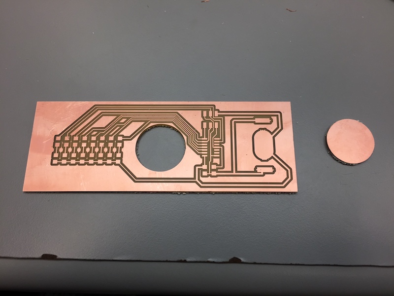
Unfortunately, the hole for the 608 bearing was just a tiny bit too small. So that will be adjusted next time.
For the input devices week, I created a smaller board with a hall-effect sensor on it and one indicator LED. I didn't want to use more of the copper circuit board than necessary, and this board was more about getting the sensor to work than the mechanics of the fidget spinning, so I created a smaller, more simple board. That being said, the placement of the sensor relative to the bearing hole is somewhat representative of what will be the case in the end product.
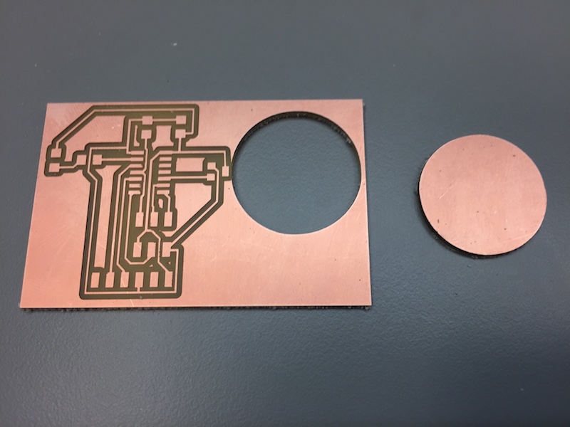
So this time the bearing hole was actually way to big. The weird thing was that I didn't even change the circle radius from the LED array board. I soon realized why this inconsistency exists: my image that cuts out the circle had a white circle indicating the cutting place. After adjusting for the offset that Mods introduces, this is way to large of a hole. The hole on my LED array board that was too small was cut out using a white background and a black cirlce, so the offset was inside the bearing, thus making the hole too small. The solution to this, I believe, is to increase the size of the circle, but still make that circle black and background white. Incrementally do that until the proper fit is discovered.
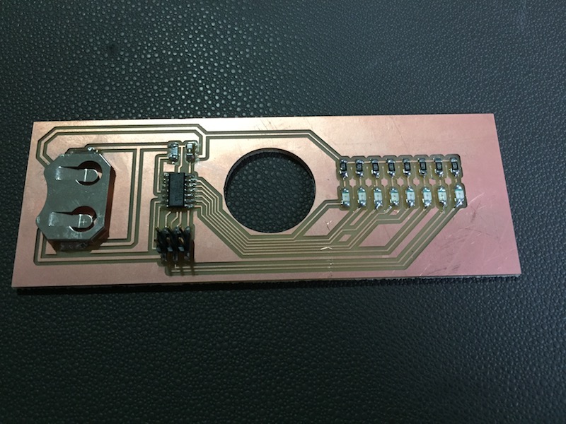
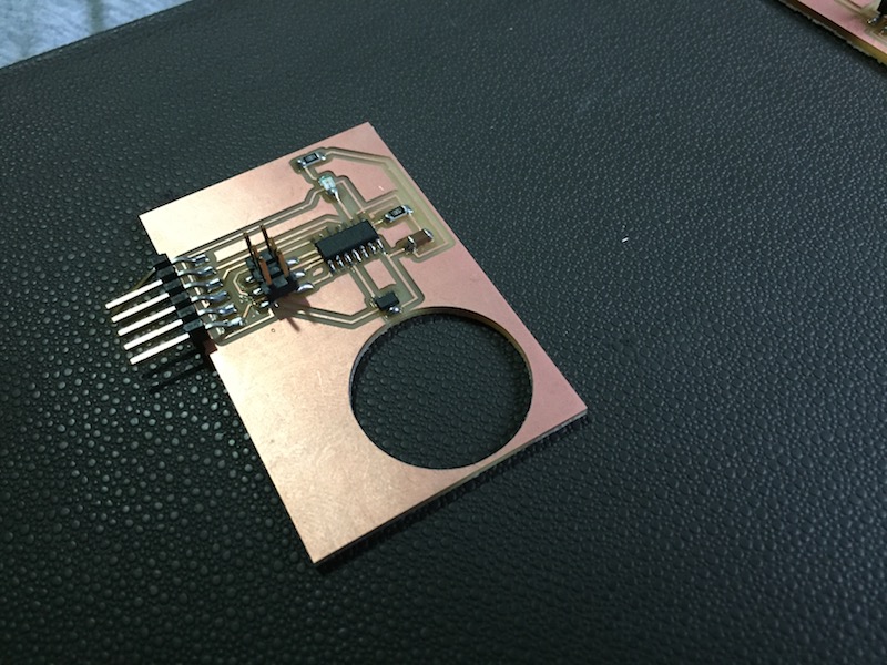
To put these boards together, I started to develop a board that included the hall-effect sensor near the bearing. The trouble I was running into was properlly routing traces to all the LEDs without greatly enlarging the size of the board. I was also forgetting to leave space for necessary traces, so GND and Vcc weren't able to get to the ATTiny44 from the ISP.
After I showed this to Neil, he (correctly so) told me to charlieplex the LEDs, so that's what I did next:
The LEDs weren't working properly because I had soldered them incorrectly after forgetting that many of them had to be put in the opposite way for the charlieplexing to work properlly... I fixed this later on.
To get started on the packaging for my fidget spinner, I thought about laser cutting options, molding and casting options, composite options, and 3D printing options. To have the form factor shape to what I wanted, 3D printing seemed like the best candidate because I didn't believe I could make the high quality composite I would need for the detail I had. Molding would have to be 2 at least 2 separate 2-piece molds, and I didn't know how the pieces would properlly fit together. Laser cutting was possibly an option, but getting 3D design didn't seem nearly as easy as just using a 3D printer. So I ended up choosing to go with 3D printing.
To start, I wanted to test some connectors because I figured it'd be the most critical, fragile, and difficult part. So I came up with a simple connector model where a 2mm diameter cylinder fits into a hole. I also printed some caps for the 608 bearing so a magnet could fit inside to trigger the hall-effect sensor. The connectors didn't initially fit, so I had to increase the size of the hole for the female connector, and then it worked well, granted the 3D prints were pretty fragile.


The above were made on the Stratesys which was really nice and had good precision and reliability. I also created them on the Sindoh with ABS, but they didn't come off the rafts well, and the holes I made were filled in with support (which because it's a Sindoh, was just more ABS) and pretty impossible to remove.

A problem I ran into when milling more boards was having my traces being extremely flared. This was pretty annoying because it hadn't been doing this previously and I think it was possibly the bit or maybe the bed not being completely straight.

Alex Kaspar had a great suggestion on how to clean that up though: he told me to put alcohol onthe board and rug it pretty aggresively with a paper towel. I did this when I remade my charlieplexed LED board (properly soldered) and it was beautiful and worked!
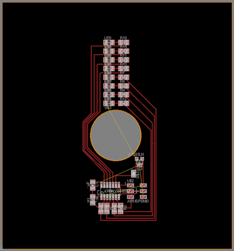
I Used the OtherMill for the first time today. It’s so much easier than using the Roland and Mods because the software takes EAGLE .brd files directly (the file of your board layout), and the software will tell you if there are any problems with clearance between traces for the given endmill you're using.


Additionally, the OtherMill mills so much faster than the Roland because it uses a different type of bit called an engraving bit. This way the mill only has to go over the sides of the traces once (or twice?) instead of doing 4 passes around the traces. While this offset is configurable in Mods, it was suggested not to lower that value. Here's the results of two boards I created, made with the Roland (left) and othermill (right).

The bad thing about the OtherMill is that the traces come out smaller than the Roland, so I wasn’t used to it in the beginning. So when I started using the Roland, when taking my first board out of the bed, the palette knife that helps prop up the bed slipped and passed over the top of the board. Since the trace width is so small, the palette knife actually ripped the trace, rendering the board unusable without adding a jumper (which would again be difficult with the small traces). However, when making boards after that first one, I increased the width of the trace from my usual 12 mils to 20 mils, and the width turned out much better.


So I just went to design the full case shape of the Fidget spinner... and man has it been a rabbit hole. I started with the intensions to have a shape like this:
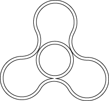
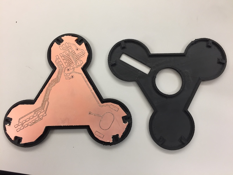
But bringing in this SVG / DXF into EAGLE produced the same weird behavior as my Molding and Casting week when I tried bringing in custom, AI-drawn chinese characters. Moving or scaling it in any way severly screwed it up. Also, there was little room for traces to make their way from lobe to lobe. So I ended up moving to a simply-built shape that was basically a triangular body with circular caps. This was also designed in AI, but I figuered the simple shapes (lines and circles) might be handled better in Illustrator. They were, and here are the 3D prints that came out:


3D print came out well, and fit together! However, because the model is (for some reason) not perfectly radially symmetric (i.e. the triangle with circle vertices isn’t actually radially symmetric relative to the male and female connectors), I fit it together in a way that was misaligned the first time. When trying to get it apart, 3 of the fragile connectors broke off. So it’s kind of a one time use thing. I could make the connectors bigger, but I want to see if I have that much space in the board layout before I move to that.
The second 3D print (which is the same as the last one) came out and I was able to find an orientation that fits together nicely and makes everything align. This was awesome, but even better, the 608 bearing fit night and snug inside the middle!


I needed to import the shape of the fidget spinner into EAGLE if I ever wanted to cut it out using the Othermill, so I needed to get the import dxf thing working. After trying to import the same dxf I imported into EAGLE to make the 3D case model, EAGLE wouldn’t accept it. To be precise, it would accept the dxf, but it only wanted to parse regular polygons such as circles, rectangles, and lines. I believe the dxf I had was probably made up of a complex or compound shape because that’s what it was considered in adobe illustrator where I designed it. More specifically, it was "complex" because I had the inside circle as part of the same shape object as the outline (so that illustrator and hopefully EAGLE would know that the "inside" of that object was what I wanted to be the "inside" of the circuit board) By "not accept," I really mean it accepted it but wasn't able to parse it correctly. Here's a pic of the script file displayed before doing nothing

My other option was to import a bitmap. I thought this would simply be like importing a photo so I exported my adobe illustrator file to be a .BMP. When trying to import this into EAGLE, it also complained because it claimed there were more than 255 colors in the image. I knew I wasn’t actually using 256 colors because I was only using 2 distinct colors. But I tried re-exporting the BMP and selected 8 bit in the export options because that would correspond to 256 colors. Again, EAGLE complained. I turned to google and found an article on Sparkfun that was showing how to import schematics as BMPs into EAGLE in order to make component pads.
What I had to do was basically open up my BMP in photoshop, convert it to a grayscale image (because for some reason the color format was still RGB), and then from grayscale convert to a 1-bit bitmap. After exporting that from photoshop, I could finally import it into EAGLE where the import BMP function basically adds a tiny 1px by 1px rectangle for every pixel in the bitmap... Sketchy. But I was able to successfully get the general shape and move it to the dimension layer.

After all this I laid out my final board and realized that the male and female connector pins for my 3D printed case would need to move. Not only that, but I’d have to import another bitmap with the updated cutouts for the connectors. And this was all after not even having a radially symmetric vector file that defines the dimensions of the PCB. Not only that but my ISP didn't totally fit properly within the outline... And after trying to fit a FTDI header in there, I couldn't get GND to the FTDI header without an obsurd number of 0 Ohm jumpers...

Frustrated, I committed to redesigning the 3D case with newly designed and newly placed connectors, and create a symmetric vector sketch of my PCB outline and 3D print inline. Instead of using Illustrator which didn’t do right by me last time... I used Fusion 360 to draw the sketch and then created the model from that. After the case was done, I could create a new sketch that incorporated the new connectors. I exported that sketch as a DXF and made a new bitmap out of that using illustrator and photoshop using the same process as last time.


My final attempt to fix the trace and component fitting issue was to try to just make the back of my board a ground plane. Xin Wen had showed me how to use the Othermill, and I knew it had capabilities to make double sided boards with vias. The nice part about making the back side a ground plane was that I didn’t even need traces on the back side. I just needed a couple vias in the right places.
When designing the board in EAGLE, I couldn’t figure out how to do the ground plane correctly. Tutorials told me to make a polygon on the bottom layer and trace around the dimension layer and change the name to ground. I created a polygon but couldn’t follow the dimension layer exactly since it’s defined by my fidget spinners weird outline. So I just created a bounding polygon and named it ground. Unfortunately EAGLE didn’t register when I put my vias that they were going to ground and it wouldn’t let me route any ground traces to them. The next thing I tried was just routing ground traces on the bottom layer like one normally would (switching from top layer to bottom layer during the route), and it allowed me to place vias on the board automatically.

When I brought my board file into the OtherMill software, it was really weird. None of the traces or vias showed up. The only traces were little marks around the vias. The outline looked like the outline of what I wanted, but seemed really thick. With the queue to use the mill stacked up, I just ran the outline job to see what would happen and hopefully be able to compare the size of it with my 3D printed case. What ended up happening was the “thick outline” I saw was actually two outlines — the mill ended up treating my dimension layer as a trace and milled around it on both sides.


This was massively frustrating and debugging the schematic was hard. Bitmaps, DXFs, lines, polygons… I was trying all these things and constantly switching failed attempts to other unused layers...
Last night I changed my EAGLE file to include a "window" for the LEDs to show through. Many of the machines have been not working, including both Sindohs, the Stratasys, and the Mills at various times... I think the shop staff are just as frustrated as the students... Finally one of the Sindohs was working and I was able to put in my new 3D case designing
I Got into EDS this morning and my 3D print on the Sindoh of my new Fidget Case was stopped. The printer needed to reboot and didn’t complete the whole print. But it got about half of the height and I was gladly surprised to see it remove from the rafts so easily. This has promise (except for the print time, which was 5 or so hours... I think this is using .1mm layer height) The circuit board that I cut out last night (that didn’t cut out the center…) fit pretty well in the case. It’s hard to tell without the connectors in though, but I have hopes that everything will fit.

So at this point I've created so many different versions of my fidget spinner board layout that I'm losing track of all of them. I realized now that when I File --> Save As to a different location (for example a Flash Drive) and keep working an an EAGLE board layout file, it won't be saved in the actual EAGLE directory... So I have a ton of boards all over the place since I've been trying to see what the Othermill will accept and what it wont.
I've been playing withe getting the outlines working a lot and the Othermill (or EAGLE) really doesn't like the idea of having this coupound outline where multiple outline cuts need to be made... Perhaps I'm just crazy and don't know how to do it correctly. What I ended up doing to get the outlines working was to separate the outlines into separate board layout files so they could be on their own dimension files. Additionally, I re-traced the bitmap dimension with the polygon tool since I thought EAGLE might like that better. Both of these ended up working. I've also been trying to get the traces adjusted because our last Othermill engraving bit (the nice one) broke and we have to use the 1/64" bit now. Below are notes I took of all the board files I was using in Othermill that I had on my flashdrive:
-
BRD Files:
- LED_Fidget_Charlieplexed_InnerV2 has via traces, an outline that looks farther out than the circle dimension, and a holes layer that looks like a circle outline inside of the circle dimension.
- LED_Fidget_Charlieplexed_Inner is actually an outer cutout (high def) with proper traces and vias
- LED_Fidget_Charlieplexed_OuterV1 has proper traces and vias with an outer cutout (but NOT the higher def one. lower poly)
- LED_Fidget_Charlieplexed is the revised version of LED_Fidget_Charlieplexed_Inner to work with 1/64” end mill
-
Mill Tries:
- 1: (Fidget_Settings_V1.png) - LED_Fidget_Charlieplexed_Inner and LED_Fidget_Charlieplexed_InnerV2 (just for the inner circle)
- 2: (Fidget_Setting_V2.png) - LED_Fidget_Charlieplexed and LED_Fidget_Charlieplexed_InnerV2
There are these really cheap Chinese knockoff engraving bits that Gavin said would probably not work but I could try. I tried one and the tip broke off a minute or so into the job. So onto using the 1/64" bit...
So I proceeded to mill the traces with the 1/64” end mill, then cut my vias with a 1/32” end mill, then cut the inner circle (different EAGLE file) twith a 1/16” end mill. Then I finally cut the outer dimension to finish the board again with the 1/16” end mill. The inner circle was imported from a different .brd file and in order to align the circle to be in the center of the fidget spinner, I had to offset the placement of the circle in the Othermill software. I wasn't exactly sure what the offset should be, so it took 2 times to get it approximately right. I took a screenshot of the settings that ended up working for me including the offset and the files I imported and what it all looked like:

It ended up coming out alright. I tested the fit with the half-done 3D prints I picked up this morning and while I don’t think the board fits perfectly within the case, it’s on the too small end of the spectrum rather than the too large end, which is great because the too large end just makes it infeasible. At least with this board I might be able to fit it into one of the cases if I ever 3D print one again today.

The Stratasys 3D printer is working. There’s a queue but I got to go first since my part will take the least amount of time. Crossing my fingers everything fits or else I might not have any more chances to fix this today...
So I finished soldering the board and I think (read: hope) everything is all good. It was my first time soldering vias and I looked up a short tutorial on Youtube but it was hard to match my experience with the video. I’m not sure if the solder is supposed to completely fill the inside of the hole or if it’s just supposed to coat the sides… My approach was basically to solder close one side (the back side) and then shove as much solder in the top as I can before it overflowed. When there was a nice solder ball on top I stopped.


My 3D parts just came out and they look really nice. And better yet, my board it’s PERFECTLY in the bottom side (with the female connectors). I’m not sure if the top will fit over it or not, and I won’t know until I desolder the ISP in order to fit it on. So I’m praying the connectors still connect. I realized partially through my print that while I had an offset for one of the dimensions of my rectangle to accommodate the male connector, I didn’t have the offset in the other dimension. Put another way, the male connectors used to be 2mm in diameter (cylinder) and the female connectors would have a 2.2mm inner radius. However, now my male connector is rectangular-ish (think 2mm by 2mm) but my female connector is only 2.2mm by 2mm. Hopefully things still fit… or worst case I break the connectors and we glue it shut!


So after checking my circuit, I found out my vias actually weren't good. There was no electrical connection between them, and after desoldering one of them, I realized there wasn't any solder between the two balls on either side of PCB. (I used the vacuum soldering iron for the first time — so helpful!) So I asked Xin how she did her vias, and she told me to shove a whole piece of thick solder in through the hole, cut it on both sides leaving about half a cm extra on both sides, and finally quickly push that half cm of solder onto the PCB without meling the inside of the via. This way, it was literally like having a solder wire stuck between the sides of the PCB. After trying it a couple times, it worked! And I could move onto the programming:
I Started out with the same charlieplexed LED program I wrote earlier to cycle through the LEDs just to make sure all the LEDs on my board were working.
When I went to program the board, I realized I put on the coin cell case backwards… I tried putting in the battery anyways and take a multimeter to it… Things weren’t making sense or I just still don’t really know how to use a multimeter, but I was concerned that when I put the battery in that the ground pad was touching both ground and Vcc traces and could possibly short. So I decided to desolder the coin cell holder.
After resoldering the holder, I programmed the board with the charlieplexed LED program I had. Thankfully, it worked, but one of the LED’s was backward. So I corrected that and everything with the LEDs is working, (yes!). The one major problem is that in bright light, you can’t barley see the LEDs when they’re all being cycled through. I had to go into a dark room to check out what the circuit looked like spinning, and noticed that when I spun it the persistence of vision wasn’t fast enough to make all the LEDs look on all the way around the circuit. This is problematic because I need to be able to arbitrarily light up LEDs anywhere around the circuit, even multiple LEDs at the same angular position.
So I changed the program so that there was no delay between switching LEDs as opposed to 1 millisecond. This made the lights so dim I could barley see them. This actually makes sense because the time of the LED being on in relationship to the time of the other instructions executing is minimized. While the delay between LEDs makes it slower to transition LEDs per second, the longer the delay the brighter the LED does seem for any amount of time. This is because the time the LED is on is larger relative to the time it takes to execute the rest of the instructions.
I was also told by other people I could consider reducing the values of my resistors from 1K because I shouldn’t be concerned with that resistance nearly as much when charlieplexing since the current is only high for a short amount of time.
So I remade a new board by again recombining two EAGLE files in Othermill to get the correct outlines I want. I adjusted the inner outline a little to compensate for it’s off-centeredness. I also fixed my Fusion 3D Fidget Spinner case files to properly account for the offset in both dimensions. I also created two new models that were slightly taller and would allow for more room for the PCB if necessary. I’ll print both out just in case.
I’ve really gotten into a flow making my board so I went ahead and make another just because it might come in handy.

With the two new boards, I stuffed one of them with the last of the red LEDs our shop has, but this time with a 499 Ohm resistor as opposed to a 1K resistor. After doing this, the lights were less dim than the board with the 1K resistors, but still pretty faint. The last board I had I stuffed with orange LEDs because they’re the most similar to red in the light spectrum and require a similarly lower amount of power to light up (when compared to blue and white LEDs). With these LEDs, I used a 150 Ohm resistor, downsizing from the 499 Ohm. When I powered it on and programmed the board, it lit up orange and looked pretty bright even when cycling LEDs every 1ms. This seemed good enough to me and I didn’t want to waste time to mill another board and place smaller resistors just to have it burn up.
- The 3D prints came out and look pretty good. Sometimes the 3D printer bed is a little not even, so the print gets a little smushed on the bottom, but it didn’t affect the connectors or the placement of the PCB, so I was alright with it. I desoldered the ISP headers on my dimmly lit board to see what it would all look like without the ISP and everything fitting in nicely.

Programming Thoughts Continued: So I’m a little concerned about being able to display all the LEDs that I want. Not only is POV rely on pulsing LEDs at the right time, but if there should be any more than 1 LED at a time on during a certain pulse, I’m supposed to use Charlieplexing to PWM that. It seems really unlikely that I can do it fast enough to get a picture out of it.
It’s also hard to translate this into proper C code. This is by far the most advanced thing I’ve ever tried to do in C, and even not having the Arduino environment is making it a lot more difficult.
In order to make sure the hall-effect sensor is working, I wrote a new script that reads the sensor and uses the 8 LEDs to output (in binary representation) the top 8 bits of the 10 bit signal. It's hard to see, but there's a video of this below: The LEDs near the bearing are the lower order bits, so they're changing the most as the magnet in the cap gets turned around:
I figured out the that max value is about 1111110xx, lowest value 11011111xx where xx are the unknown least significant bits. I'll probably try to use these to write a thresholded program to sense when the magnet is closest to the hall-effect sensor.
I ended up re-doing the case (again!) in order to add a hole for the ISP (I didn’t want to desolder them) and because the cases that have been coming out lately have had some issues in at least one of the three corners…

The final program I got working for demo day was a program that took the hall-effect reference upon putting the battery in, and then if the magnetic field got weaker, the LEDs would go on. If the magnetic field got stronger, the LEDS would go off. (Video below)
Completing the Letters turned out to be more difficult than I anticipated because it wasn't as simple as calculating (or estimating) the angle at which the fidget spinner was at and turning on those LEDs. Because the LEDs were charlieplexed, if more than one LED had to be on at that moment, it was impossible to turn both of them on. Even if I quickly switched between the LEDs, by the time all of them had cycled, the spinner would have turned a non-trivial distance. I know that this is all possible to figure out and handle properlly, I just didn't end up completing the letter display before time was up...
Final Output