Input Devices
This past week we explored a plethora of input devices that can provide useful information to our ATTiny microcontrollers. The reason I believe we started with output devices was because without any output, taking input is somewhat useless. You typically want to make some sort of change based on input, but if that change is invisible to the user, there isn't much point.
Orienting Ourselves
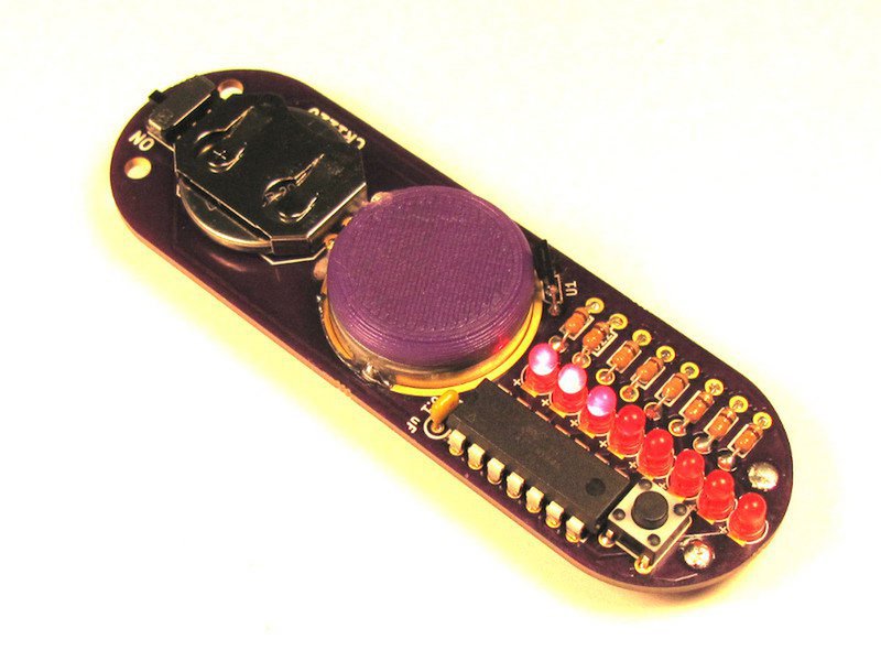
This week I wanted to continue working towards my final project of a persistence of vision fidget spinner. Where input devices come into play with this final project is in the detecting of orientation or angle at which the fidget spinner is. If you think of a fidget spinner like a clock, and the lobes of the spinner as a hand on a clock, the hand will keep going around and around. That hand is driven by gears that have been turned a precise amount. But my fidget spinner won't have any gears to drive its movement. Instead, there will be a bearing in the middle that allows it to freely rotate.
Therefore, in order to understand what "time" it is - i.e. where the lobes of the fidget spinner are in relation to the bearing (which is directly related to how the person is spinning it), I need some way of measureing that relationship. One way people have done it in the past is by using a magnet stationary within the bearing caps, and put a hall-effect type sensor on one or more of the lobes.
This way, if there's one hall-efffect sensor, it will hopefully get a "spike" or "pulse" in it's reading of the magnetic field whenever it goes by the edge of the cap. From there, you know that at each "pulse," the orientation of the fidget spinner is the same. If two hall-effect sensors were used, then every two pulses the orientation would be the same.
Additionally, to approximate where the lobes are at any point in time, you can count the time between successive "pulses" and divide by 360 degrees to find out approximately how far the spinner might be. This is assuming a constant speed (which we know isn't true), but with some more mathematics, you can approximate the acceleration of the spinner and account for it slowing down to get a more precise estimation of where the lobes are.
Building Hall-Effect Sensor
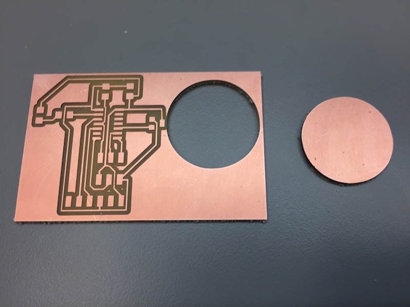
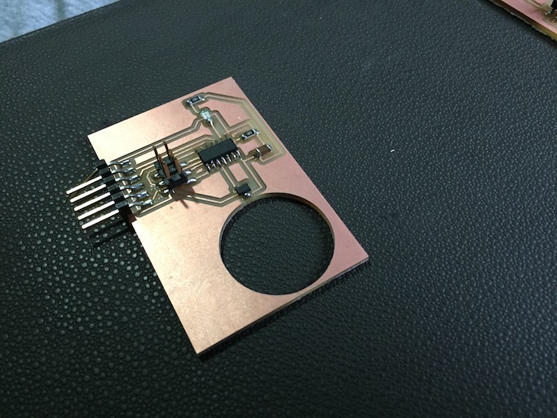
I started with the hall-effect sensor design on the input devices page. The changes I made was I used an ATTiny44 instead of a ATTiny45 (in hindsight for no good reason) and I added an LED for any debugging purposes. I also added another hole to put a 608 bearing. I finally got 608 bearings and found out it didn't fit perfectly into the LED array board I had built for input devices week. So this time I still used a 22mm diameter circle but this time will swap the colors of black and while in the outline traces such that Mods will cut more close to the traces than last time. We'll see how it goes.
So the hole for the bearing came out too big. It was suprisingly much more off than the LED board, so it seems like the next time I try a hole cut, I'll just slightly increase the diameter of the hole (~22.5mm) and cut it in the same manner I cut the first hole on the LED board.
Programming the board
So I referred back to the ATTiny44 datasheet this week to look more closely at the ADC peripheral. I also started with the code that was for the ATTiny45 that had serial output set up to send the ADC output to my computer. Changes needed to be made because the pins on the ATTiny45 and ATTiny44 aren't the same, and the ADC configuration pins aren't the same either.
There was this strange reference to REF2 bit in the code that I didn't understand. It wasn't in the ATTiny45 datasheet or a part of the ADMUX, so it didn't seem like it was doing anything. Either way, I understood I wanted to reference the hall sensor to Vcc which just involved setting the REF0 and REF1 bits to 0 as indicated on the data sheet. The MUX[5:0] bits are to choose which pin's ADC you want to read from (at least in single-ended input channels). Finally, there's the ADCSRA register that allows you to enable the ACD, set bits for enabling auto-conversion and interrupts, and set the ACD prescaler. We aren't interested in auto-conversion nor triggering interrupts, but the prescaler option was interesting to me. Neil set the clock division factor to 128. After looking back at the datasheet I figured out that it's most stable to run the ADC between 50kHz and 200kHz. If I set my ATtiny44 clock speed to 8MHz, then I can prescale that by 64 to get a sample rate of 125kHz, or by 128 to get a sample rate of 62.5kHz. Since I don't really feel the need to have the extra samples, I left it at 128 prescaled clock.
After adding in logic for turning on the LED when data was being transmitted, I thought I was all ready to go. After trying to upload the code to the ATTiny44, I was getting the following error:
avrdude: Device signature = 0x1e9207 avrdude: Expected signature for ATtiny45 is 1E 92 06 Double check chip, or use -F to override this check.
I had changed the device to ATTiny44 in the makefile and couldn't understand what was going on. After a little bit of searching, I realized there was an additional flag being put into the makefile for the "program-usbtiny" command. There was a little "t45" there and after checking some of my old ATTiny44 makefiles, I confirmed that there should instead by a "t44."
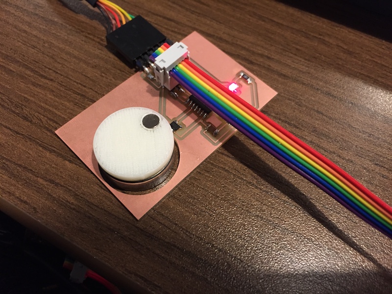
After getting the code all set, it uploaded and worked! My tiny magnet didn't make much of a difference to the hall effect sensor as I would have hoped, but the fluctuations proved that the circuit was working including the ADC!
Moving on from here
This was all really cool and defniitely more complicated than I would have expected for what Arduino simply calls "analogRead()". The power of being able to use the ADC come into play when hooking the ATTiny up to other modules that, similarly like the hall-effect sensor, send out some piece of analog data. These sensors include distance sensors, temperature sensors, force sensors, and much more!
Other things I'd like to explore later on include the ADC interrupt capabilities and referencing a different input voltage. And finally, because Neil talked about the expansive capabilities of parsing step responses based on resistanec, capacitance, etc, I'd like to explore that further as well.
Terminology
Analog to Digital Converter (ADC), Digital to Analog Converter (DAC), comparators,
Technologies Used
Hall Effect Sensor, Magnets