I Can See My Microcontroller Thinking
This week's assignment was to make a board with some output device. Since I plan to make a persistence of vision fidget spinner for my final project, I thought this week would be a good opportunity to start building up the LED component of the board.
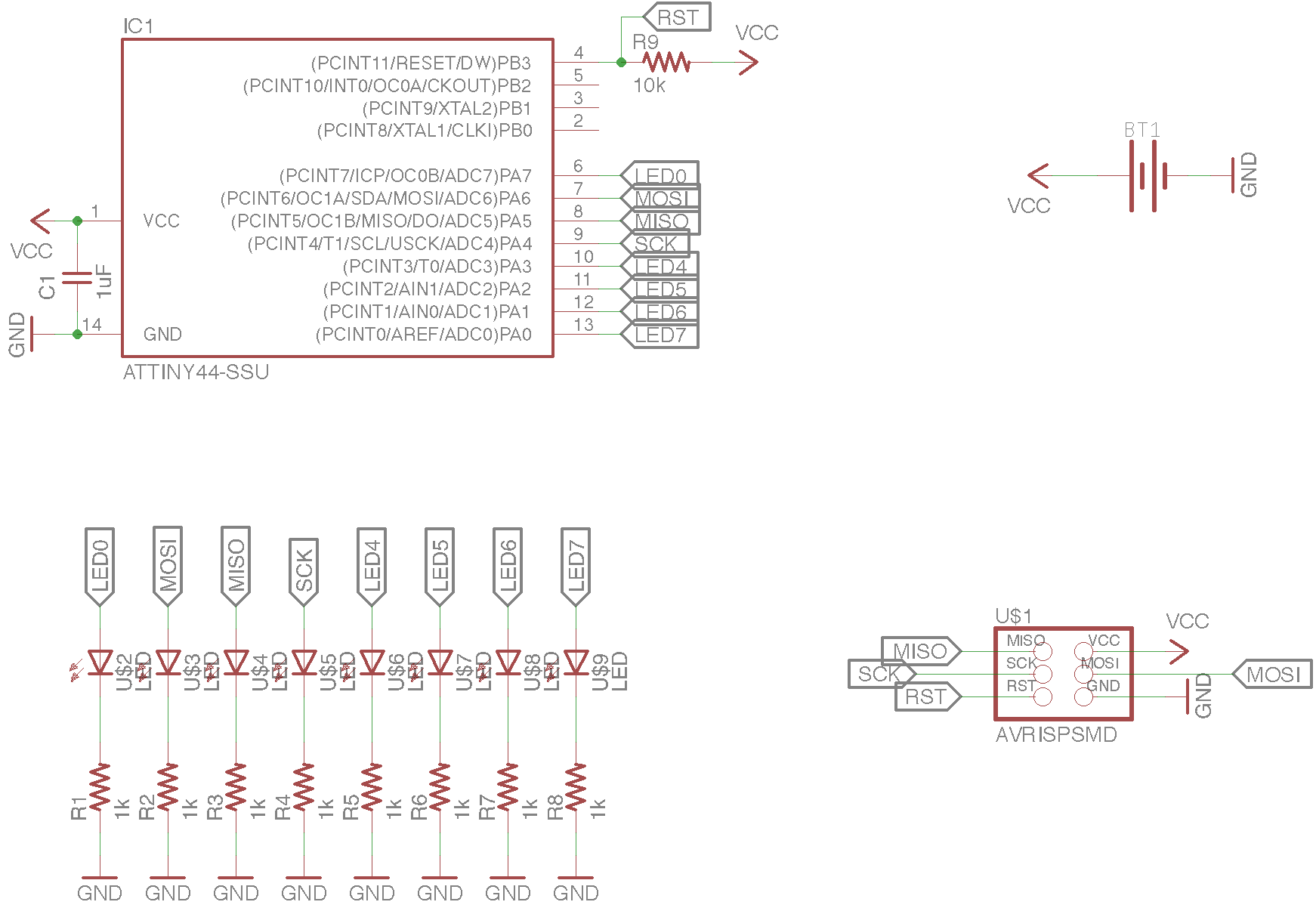
So to start out, I created a schematic containing 8 LEDs that each connected to its own pin. I wasn't sure whether I was able to use the same pins that my 6-pin ISP connector was attached to (such as MOSI, MISO, SCK), but I saw other examples of boards that had used the same pins, so I ended up using the same pins. I heard Neil briefly talk about Charlieplexing during class, but after reading the document I was still terribly confused. So I thought I'd start by making a board where each LED has it's own pin.
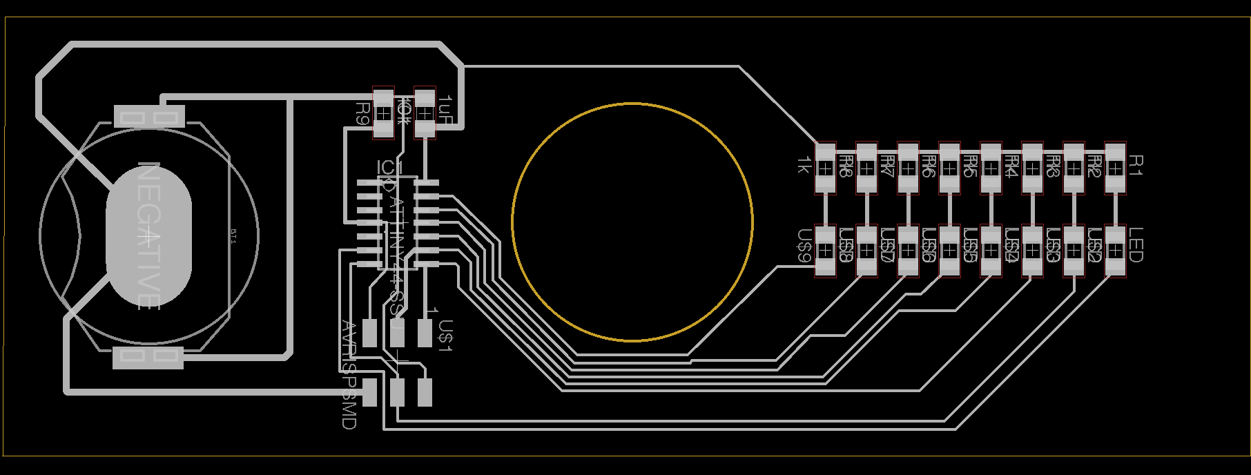
The layout of the board was a little tricky because I wanted to include a hole for the 608 bearing I would eventaully use for the middle of my fidget spinner. After trying to draw a tri-lobe fidget spinner outline in EAGLE, I kind of gave up because EAGLE isn't a drawing program, it's a PCB designa and layout program. So I resorted to makeing a board that would be a bi-lobe fidget spinner because the one thing I could draw was a circle with a 22mm diameter.
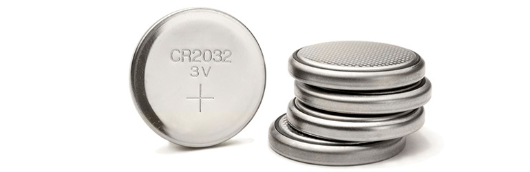
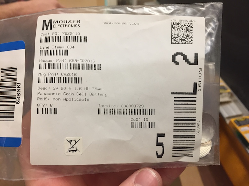
Another challenge in making the board schematic and layout was thinking about how to power the board. Until now, the boards we've created have either been powered by USB directly (TinFABISP) or by USB to FTDI (Blink Board). Either way, this was a tethered power connection, which is infeasible for a fidget spinner. I needed to power it on-board, and the simplest way I thought to do that was by using a coin cell that would fit on the PCB. A coin cell looks like:
And fit into a holder like:
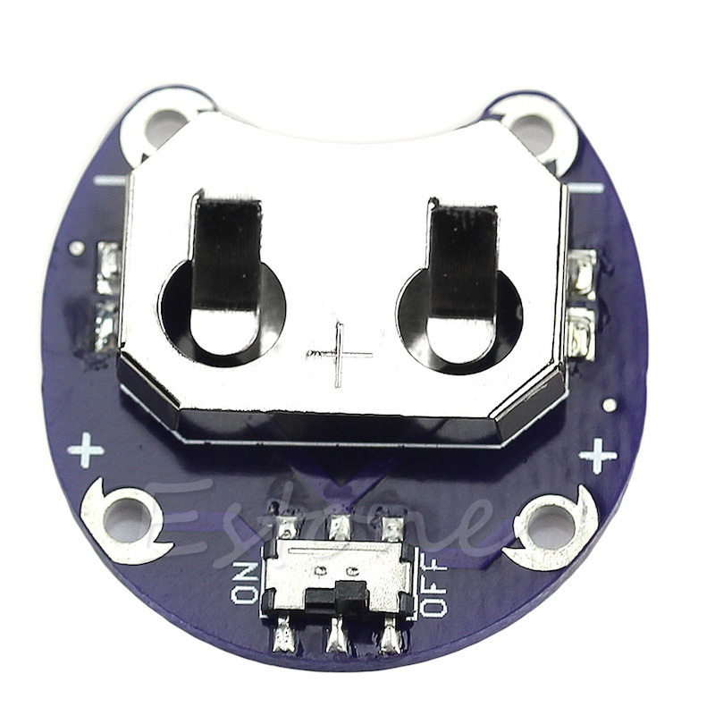
The trouble was, the Fab inventory didn't have any coin cell holders. I asked my shop manager if we had coin cells and he said yes, but we would have to buy more holders. He gave me one holder and told me to look up the part and schematic online.
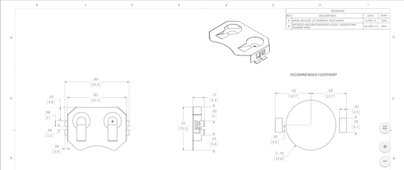
So I looked it up and the coin cell part didnt' tell me much about any holder, but I found an appropriate size holder (20mm diameter coin cell) and looked at the datasheet. While I now knew the approximate dimensions of the holder that I'd be using, it didn't give me an actual EAGLE board layout part.
After looking a little into how to make my own EAGLE parts, I thought there must be an easier way. So I did a little searching and found that Sparkfun publishes their own EAGLE part libraries, and Sparkfun had a very similar battery holder to what I needed. So I downloaded the Sparkfun libraries and imported them into EAGLE. From there, I could create the board schematic and layout I needed.
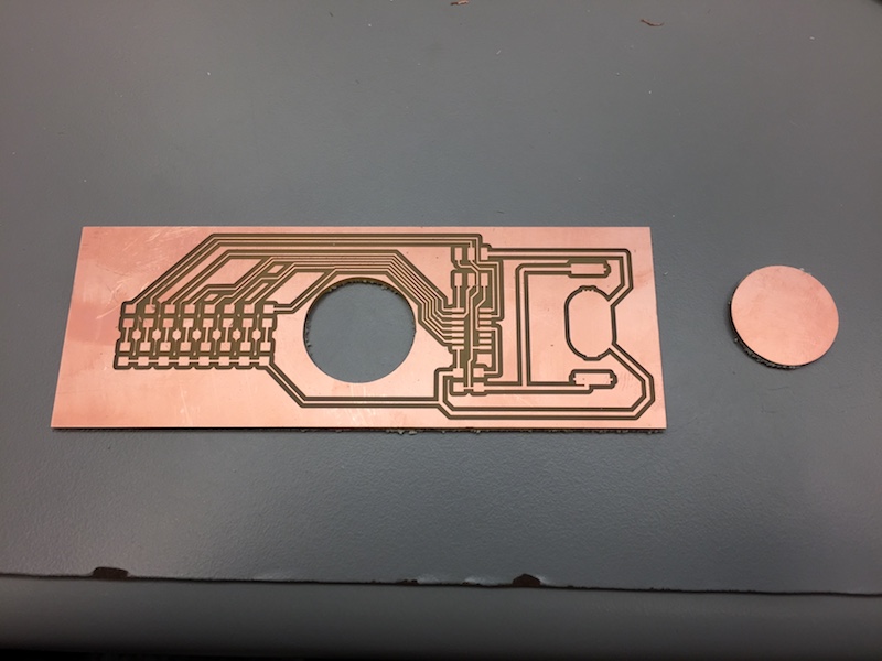
When designing the board in EAGLE, I made sure to use bigger trace widths between the battery and the ATTiny44 so that there wouldn't be any current carrying capacity issues. Additionally, I again had some milling clearance problems with some of the traces that were wrapping around the center circle to the LEDs, but after I cleared those up it was relatively smooth to mill out and stuff.
Additionally, to cut out the center hole of the board (where I will hopefully place a 608 bearing), I ended up creating two "outline" image files. One with just the inside outline, and one with the boarder of the whole board. This way, I made sure that I could cut the inner circle first before cutting out the rest of the board. If I had done it the other way around, any movement of the board could cause cutting the inner circle to be misaligned and potentially cut the close traces to it.
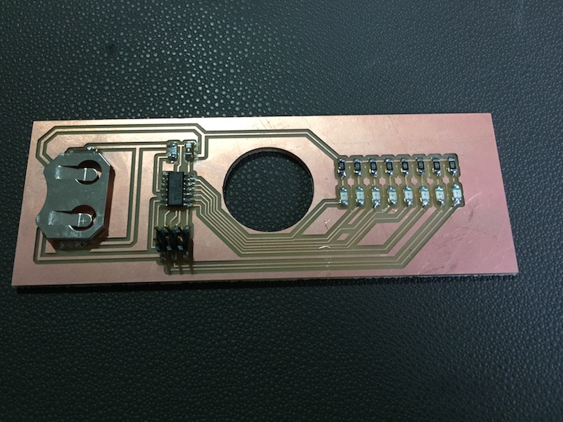
At this point, I'm finally feeling more confident about soldering surface-mount parts. I've definitely established more of a flow and process, which is pretty fun considering how aggrivating this was all this way back when making the FabTinyISPs. That's not to say it's not annoying when you mess up and have to de-solder. That's still a pain, but I definitely don't have to do it as often.
Programming the Board
Because the LEDs are in an array, each connected to a different pin, it was fairly easy to program after the amount of suffering that went into the Embedded Programming assignment.
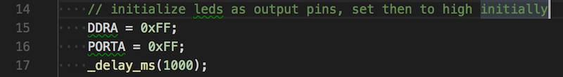
I very purposefully set up my LED schematic so that the 8 LEDs would take up all 8 pins of PORTA on the Microcontroller. This way, I only had to set all of PORTA to be output pins:
And then to cycle through the LEDs and flash each one with a delay of half a second, I used the following code:
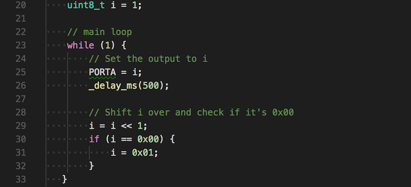
If I were programming in a higher level language, I would've approached this by iterating through the index of the LED (0-7) and turning on the LED at that index (perhaps with the addresses of the LED stored in an array or something). However, since this is C and so close to the hardware, I know the only different between turning on LED0 and LED1 is the different of 1 bit in the same register. This way I can exploit using bit shifting to move which LED is turned on in the register. I thought this was pretty cool and quite a different way of thinking than what I'm used to in software engineering.
And finally, to see what the LEDs would look like when trying to cycle through them as fast as the processor could take, I removed the delay in the while loop:
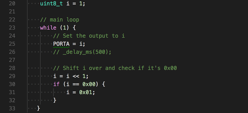
There was a noticable differen't in brightness between the startup LEDs (where each LED was on concurrently) and the LEDs during the loop. Because the LEDs are only on one at a time, doing this was essentially kind of like using Pulse Width Modulation to control LEDs. We know PWM is used to dim LEDs by not having them on all the time, thus releasing less light per second than it would be if there was a constant current applied to the LED. So it made sense that the LEDs would look dimmer.
Next steps are definitely trying to create the Charlieplexed version, and making sure the LEDs in that version (in which only one LED can be one at a time) also are bright enought for the final fidget spinner. Check out the Final Project progress page to stay tuned.
Technologies Used
EAGLE, Roland Mill, LEDs, Coin Cell