This week, we learned how to use Eagle, a PCB design software. It was a lot of Eagle.
Learning how to use Eagle this week took much longer than I expected and I'm still not really sure why. There's no way I would've made my board without the help of Max and Vibha so here's a quick shout out to them!
Downloading and getting started was easy enough. I followed this tutorial MAz showed me to understnad the basics about moving, rotating, naming, connecting, and setting the values of components: tutorial. This first hard part was figuring out what parts to pick:
Problem: Picking the parts
Solution: The first step was to download the fab.lbr library which is hidden in the circuits grouping of this page. You can navigate through it in Eagle (see tutorial) but make sure to scroll - you can't really search. To pick the parts, it helped to do a visual matching. When you select a part from the library it shows up on the side and if you know how many pins, etc. the piece has you can rule a few choices out. To figure out the ISP I had to ask someone and for the resistor and capacitor I picked the ones that said FAB. You don't need to consider values and this point, you type them in later.
Problem: Picking the values
Solution:> To figure out the values of the resistors you add to the button and LED you have to do a simple calculation. Look at your LED/button and see what current it requires. Then figure out what voltage your power supplies. Mine was 5V. Then use the V = IR equation as R = V/I to solve for the resistance you need to attain the current. Too small a resistance and you fill fry your part. Too big and I'm assuming the light won't be as bright.
Problem: Making the Schematic in a readable way
Solution: I looked at a person's schematic from last years website (really have to use all my resources on this one) to figure out cleaner ways to make the schematic. Looking at Amira's website, I found a few easy tricks. The first is to make connections by labelling wires with the same name. There are a few steps to do this, but you can find it in the tutorial I linked. When you do this, Eagle will ask if you want to create a connection. Say yes.
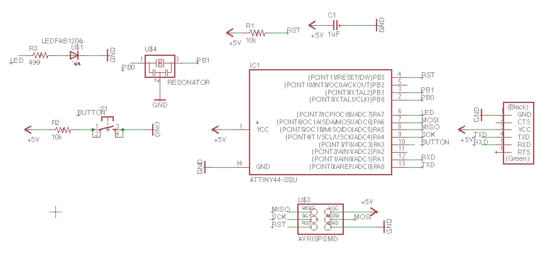
This is what my final schematic looked like:
Putting the board together is like a puzzle.
Problem: Puzzles are hard
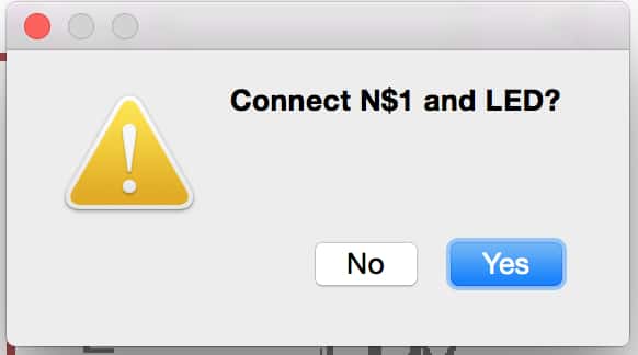
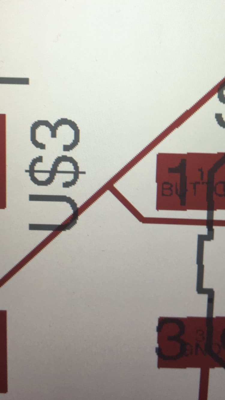
Solution: First, don't be afraid to really move the pieces down if you can't get the right connections. Second, start with the big connections (connect all the grounds for example) and then don't be ashamed to use the autorouter to finish up the last connections. Do make sure you check the connections the autorouter made. This type of junction is bad:
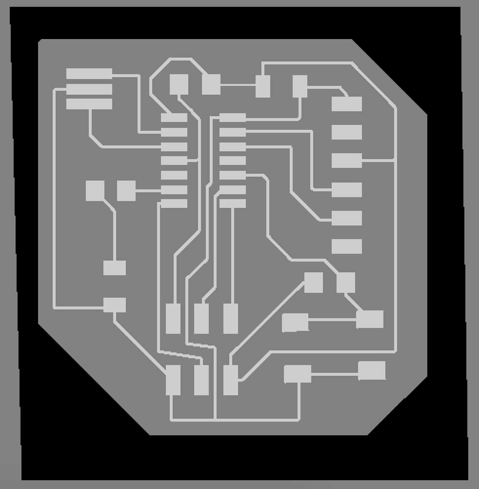
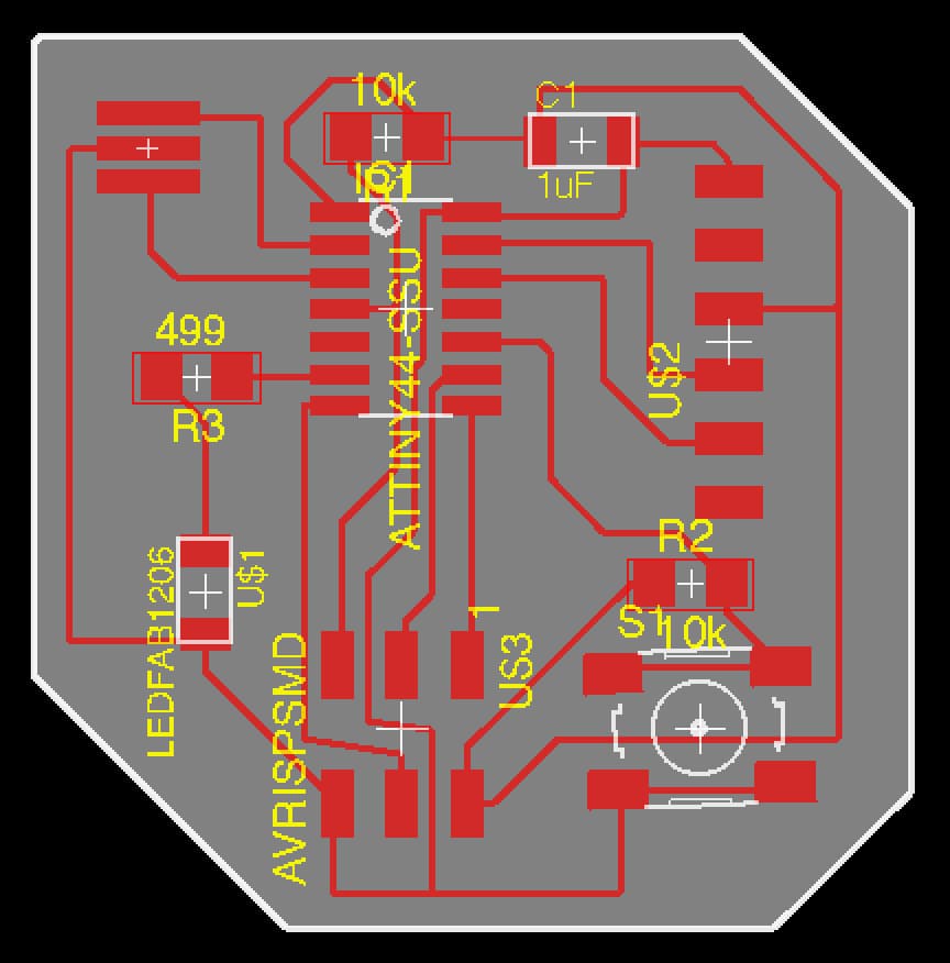
Other than that, my general steps were to place the pieces in the general layout of the picture we were given for the assignment. Then I placed the extra part in empty space. I ended up moving the pieces around a lot so I don't know if this is the best approach. This was my final board:
Problem: Layers and Exporting
Solution: You need to only highlight you "Top" layer when exporting your trace file (png). Do this with the layers tool in the toolbar. For the outline, you can do it one of two ways. The first will let you draw a polygon for your outline and is: 1. select only the 20 Dimension layer 2. Draw your own lines using the same width you used before 3. Export only the dimension layer. The second will let you have a box for your outline and is: 1. select only the 20 Dimension layer 2. Using the move tool, drag the lines in where you want them. It is really hard to get them to be perpendicular and straight. 3. Go to Options>User Interface and set the Background to Black 4. Export only the dimension layer.
When you export, use 500 dpi and monochromatic. The trick is do NOT adjust (scroll for example) the window of the board diagram if you are going to export with the Window option. It takes the entir view of what your exporting. The reason you don't want to move it, is you want the origin of the picture to be the same when you put it into the mill. This is also why I would avoid editing peripheral space in Photoshop. Again, this problem would not have been solved without Max, so thanks Max! I would reccomned just using the full option, and narrowing down the your board to include as little extra space as possible.
Milling
Problem: Size; When I started milling my trace, it was twice the size it should have been.
Solution: Look at the dimensions of your trace and outline files. Mine were in the thousands, around 1600. This meant that when I uploaded the pngs into the mod program I had to use a dpi of 1000, instead of 500, to get the right size.
Problem: Mill Not Connecting
Solution: This one was hard. I had to look at the terminal to see the errors. First, I just had to just the lp0 to lp1. Easy enough. However, after my first print, the mill stopped responding to the mod program - it wouldn't move to origin, etc. I restarted everything then had to use a sudo command to manually reset the communication with the printing machine:
sudo node /usr/local/bin/printserver.js 127.0.0.1 1234
Thanks Alex K for the help on this one!
This is what the final cut out of my board looked like:
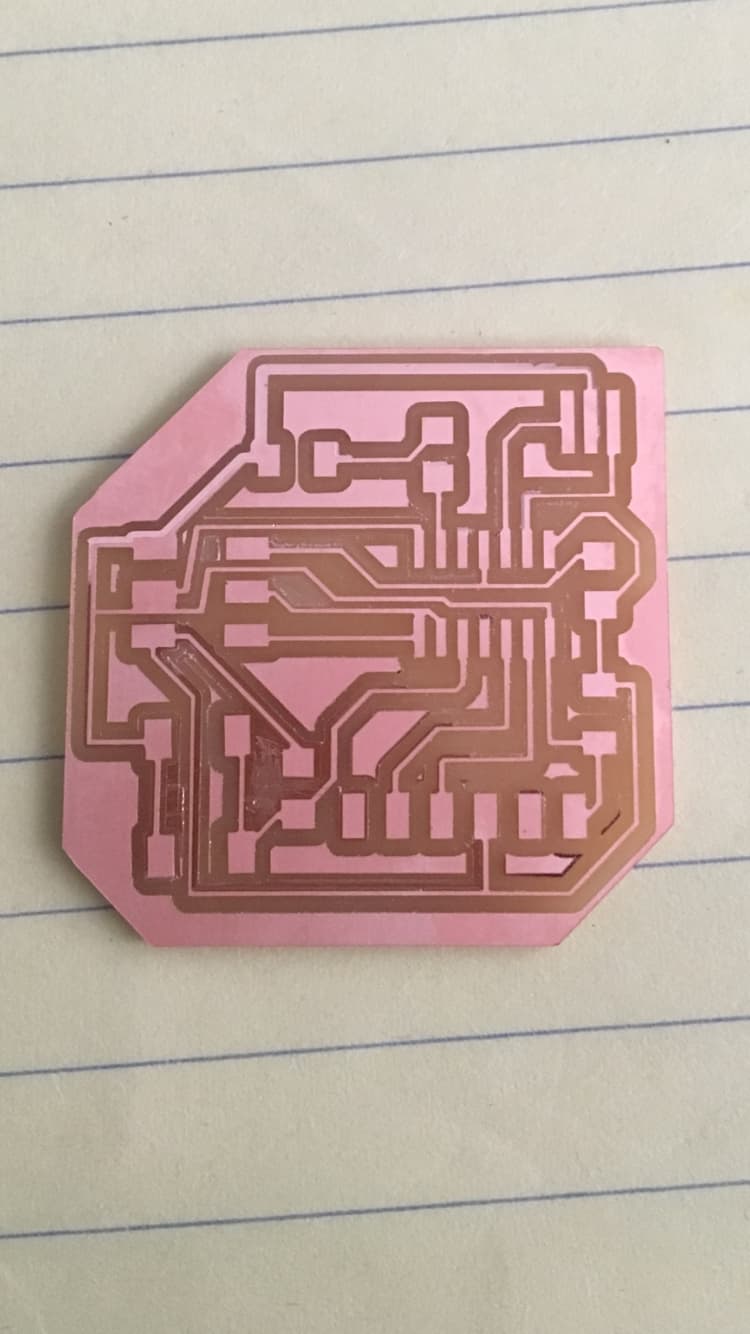
I have all the parts and see that they will fit on the board, but still need to sauder and program it.
I made three boards, but none of them worked.
First, I tried to program my board from last week*. When I ran the sudo command to make the fuses, it said the initialization failed and to check the connections. First, I detached the programmer andran the command to see if it would recognize it was disconnected -it did. Then, using the multimeter** I checked every possible connection and every area with a problematic non-connection. Then, when nothing seemed wrong, I checked all the directions of my components. Only the ATTINY and LED were polarized and they were on the right ways***. Of course, I checked all the sauder joints. Finally, I replaced the ATTINY to see if it was a dud. It wasn't. When I milled this board, it left small amounts of copper in between components that weren't supposed to be connected. Dave and I managed to etch of these parts using a utility knife and they definitely weren't connected, when we checked with the multimeter.
*To do this, first connect your board to only the programmer (and programmer to computer). Then, once the board is theoretically programmed, you will connect it with just the FTDI cable through the 6 pin connector.
**Use the multimeter to look for shorts or unconnected components. To do this, turn the dial to point to the diode symbol and press mode. You should hear a beep when you touch the ends of the pins to each other, basically whenever it is shorted.
***To check direction, you can look at the board in Eagle and zoom in to see which parts on your directional components are labelled ground. For the LED, the marked side should be the cathode and connects to GND. For the ATTINY, the Eagle board shows a circle that you can see on the microcontroller. Match them up. I double checked the data sheets of each component to make sure that these markings and directions were correct.
I decided to refabricate the board because of the initial milling issue I had. This time when I milled, I pushed the traces 1/64 mill down a little more firmly into the bed and it milled beautifully... except for one piece of copper I had to cut. I populated the components, but the board still didn't work. I realized that the LED I was using had slightly different connections than the one I specified. Theoretically, the LED and button should not inhibit the programming of the board, but just in case, I tried with a different LED but still got the same board not initializing error.
I decided that, at this point, it must be my design. I went back and made a new design in Eagle. I increased the path thickness to 12 (from 9) but I don't think it really mattered. A good trick is to test the design in mods, which you can do from your own computer by going to mods.cba.mit.edu, before going to the mill. This let me triple check the vectors when I "calculated" the image. I kept adjusting the trace file and viewing it in mods until I had a perfect vector path. This took nine iterations, but this time the board really did mill perfectly. I populated and tried with both LEDS, but still no luck.
These are the two populated boards (I reused the components off the third. Removing the components using a hot air gun is easy, but I found the tongs to be even easier.
This time I decided to look at other poeple's pages to see if they ran into the errors I was getting. I used rgep to search our gitlab folder for the word serial and found that Alex had gone through the same problem of having to download pyserial ("a python package with backend for python to access serial port. A serial port is a port on your computer through which bits, actual 1s or 0s are trasmitted - use Google for EVERYTHING!). I'm really glad I looked at Alex's page because he ran into problems with pyserial and it saved me some time.
This link helped me install all the necessary components to use the serialport npm package. If the node installation stalls for a long time on make install (or the make command for that matter) it's ok. Here is some more basic information on Serialport.
Then use "npm install serialport" to actually install the package.
I used the page Alex linked to read about serialport term. Then I used the command "serialport-term -l" to get a list of all the ports and used the one that said usbserial in the command "serialport-term -p /dev/usb/tty.usbserial-XXXXXXX -b 115200". The X's can change everytime the FTDI cable is disconnected so it's best to use tab complete.
Anyway, I explored serialport-term for a while but kept getting "Error: No such file or directory, cannot open /dev/tty.usbserial-FT90UD4L" even though I checked that was the right ID number.
So then I went back and decided to try python3. The serial import was correctly recognized with this.
Since the code was written in python 2, I had to add parenthesis to the print statements. I also had to update the tkiner as described here. Finally, there were unrecognized characters istead of spaces. To find them, I Ctrl-F found the character (I think it was Alt-A) and then replaced them manually. You're supposed to be able to do mass find and replace with vim with vim -> :ret, but it didn't work and it was just a few lines so it was fine.
Then I got a permission error saying I didn't have permission to use serial device tty.usbserial-XXXXXX. To fix this I ran the commands "sudo adduser MyUser dialout" then "sudo chmod a+rw /dev/ttyUSB0". To find out what to put in the "MyUser" spot I ran whoami.
After this it programmed and the light turned on! The echo hello world works. While it opened it the separate screen on the Linux lab machine, on my mac the echo just happens within the terminal. Figuring all this took me a few weeks, which in hindsight is pretty funny :)