Assignment: Plan and make a machine.
Planning
We started by getting together on Wednesday evening to figure out what we wanted to make and how to divide up the work. We decided not to overcomplicate things, and stick relatively closely to Jake's original design. Jiabao and Honghao suggested the idea we ended up going with: a glow in the dark UV art printer. It's light painting! Our end effector in this case is a flashlight. We can control it in the X and Y axes to "draw" monochrome image designs onto a glow in the dark surface, control the Z axis to change stroke width, and turn the flashlight on and off with an additional actuator. It will seem invisible until you turn off the light -- then you've got art!
We also split the project into three parts: machining, programming, and assembly, and had people sign up for each of these groups.
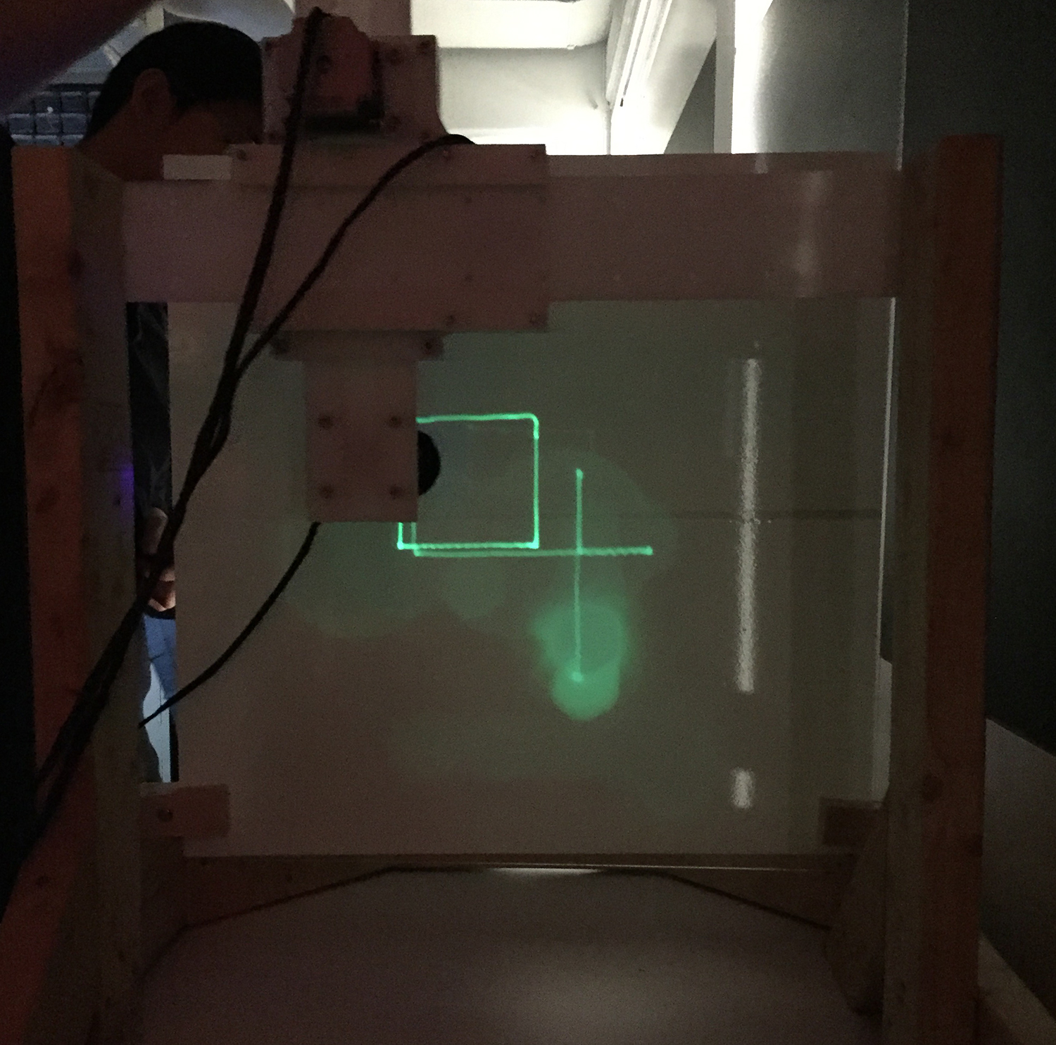
Result
follow this link to know what goes wrong on this one.
End Effector
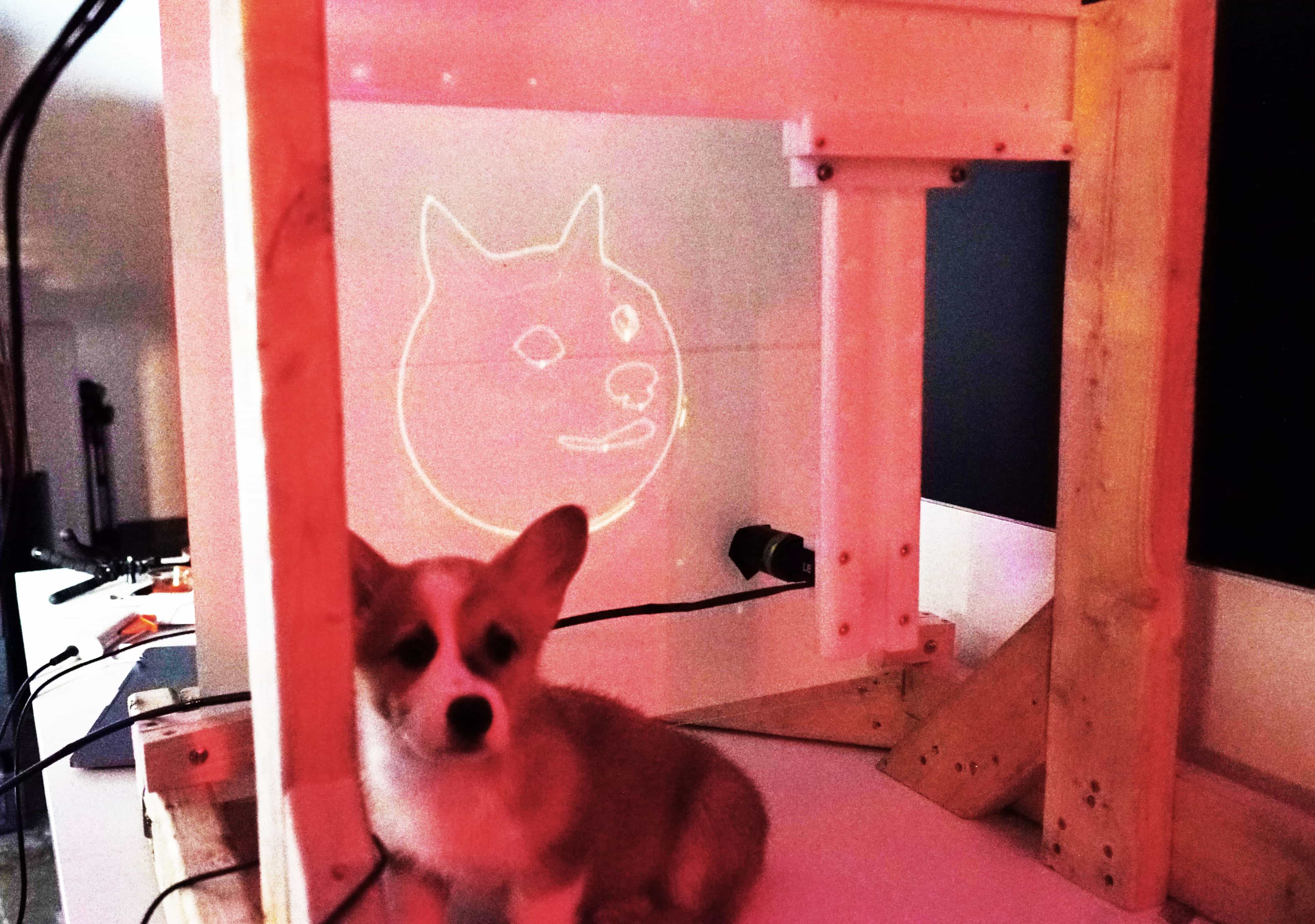
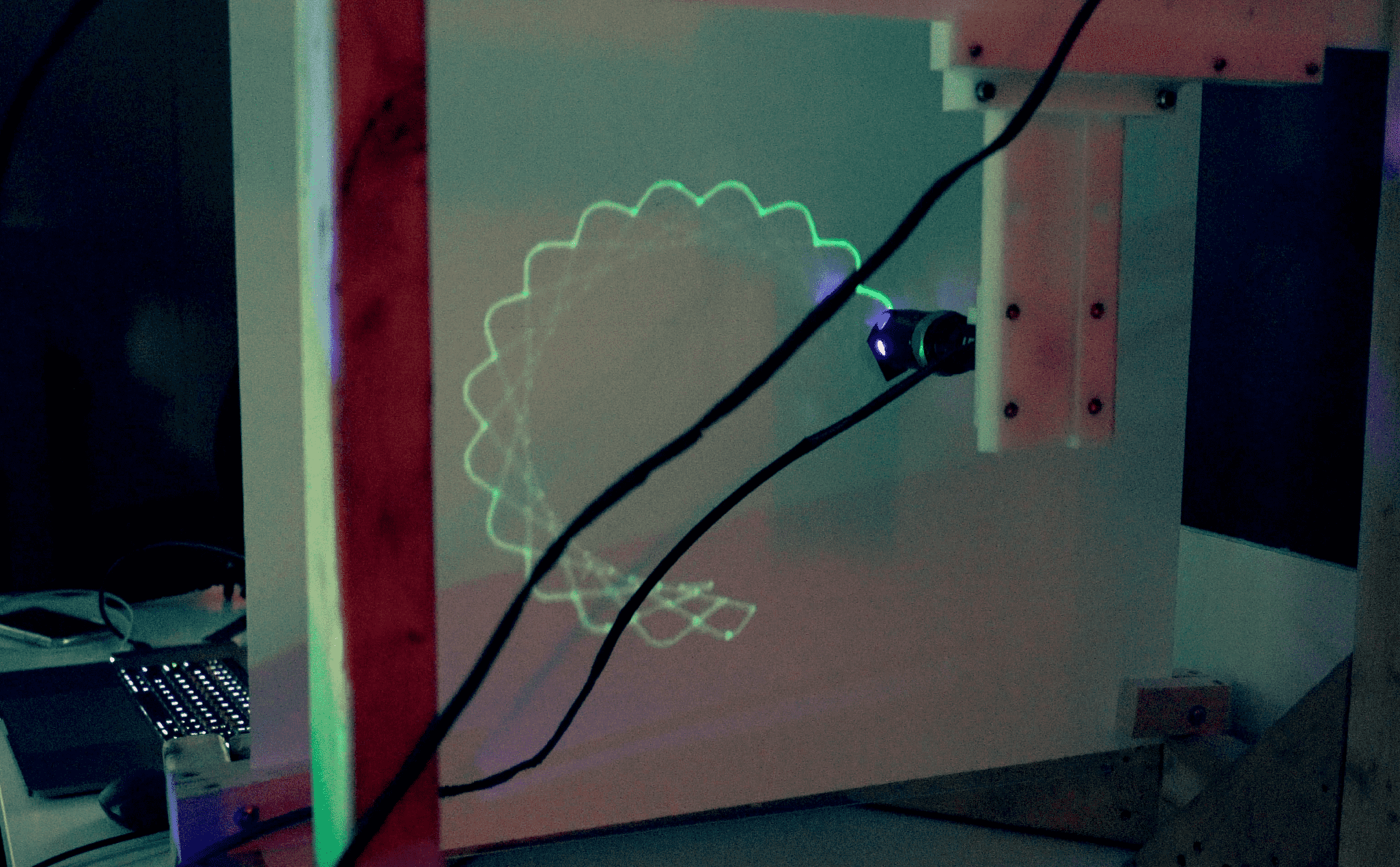
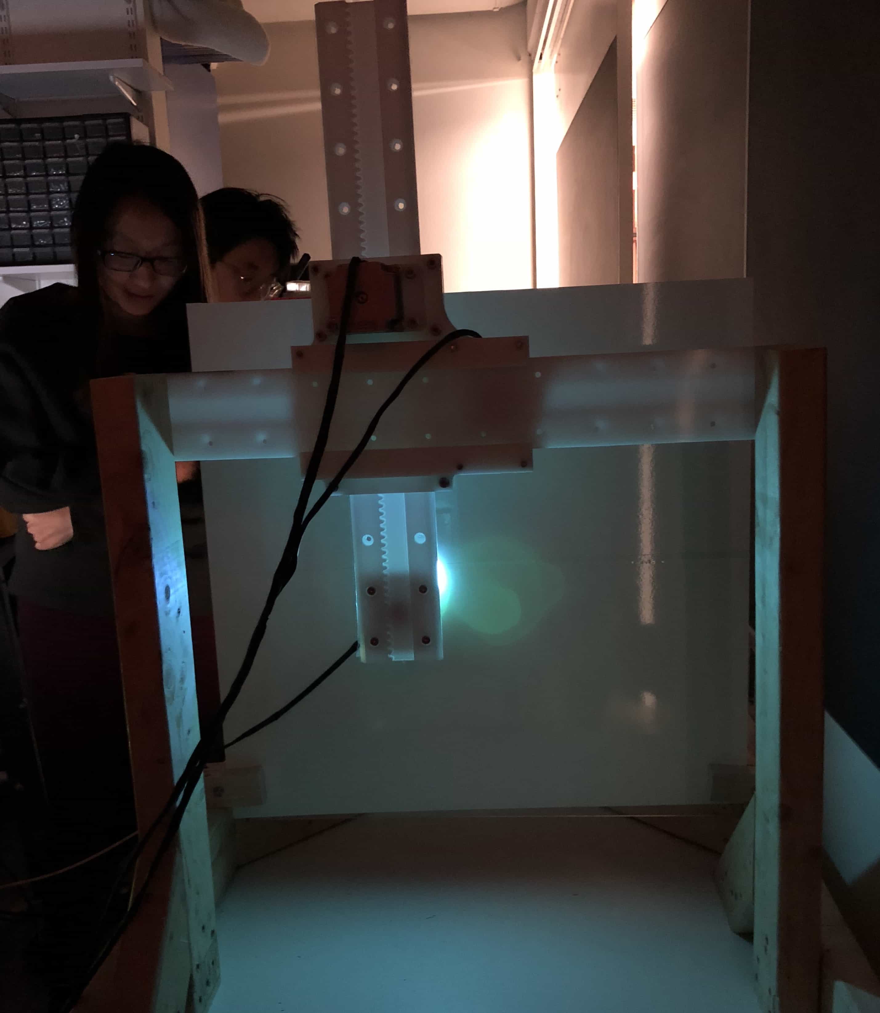
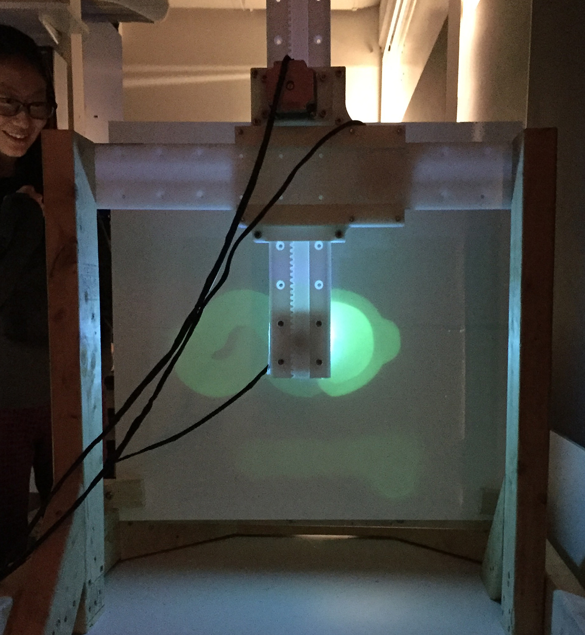
We are using UV light as paint brush. The "Glow-in-the-Dark Luminous photoluminescent / luminescent emergency roll" as the canvas. The light disappears after a while, so the canvas can be forever reused. The ephemeral of the painting makes it unique.
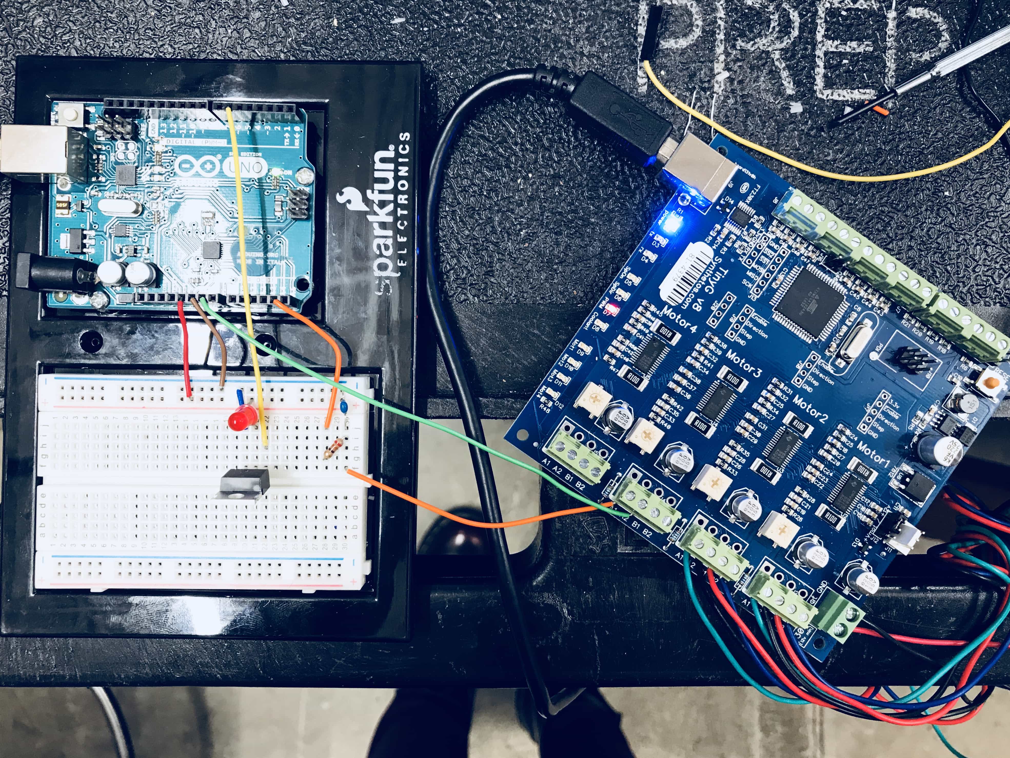
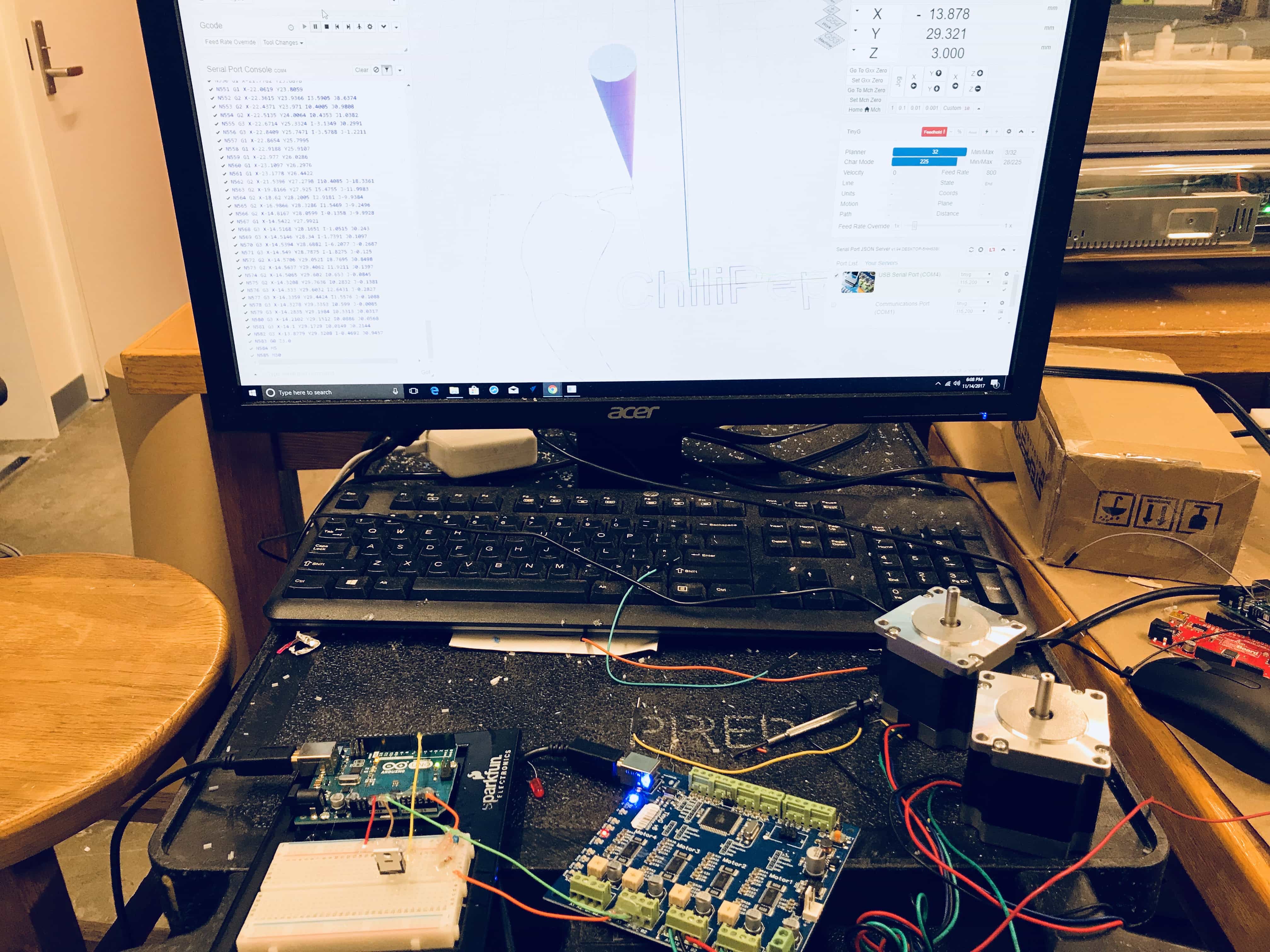
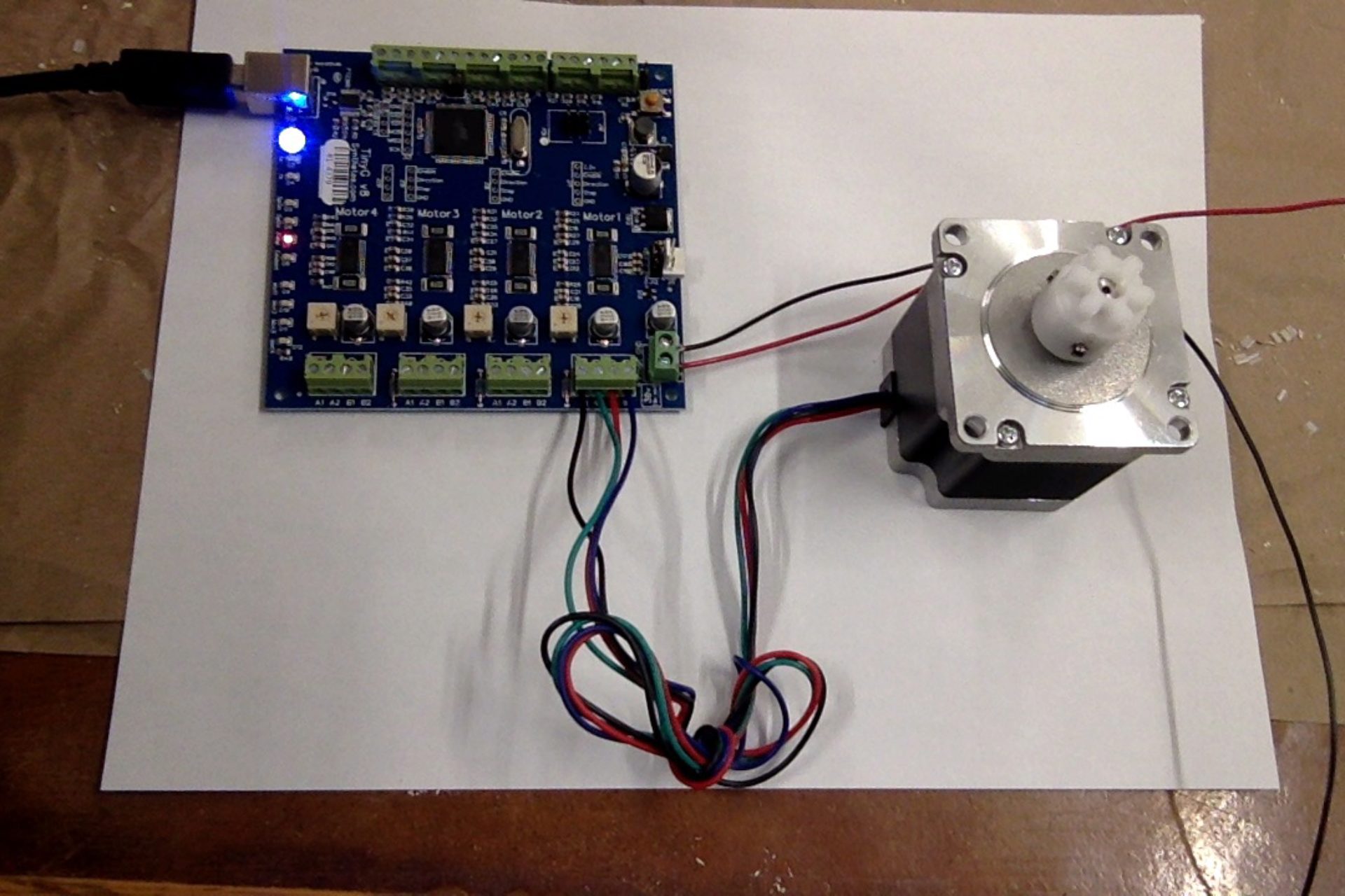
The final board with TinyG.
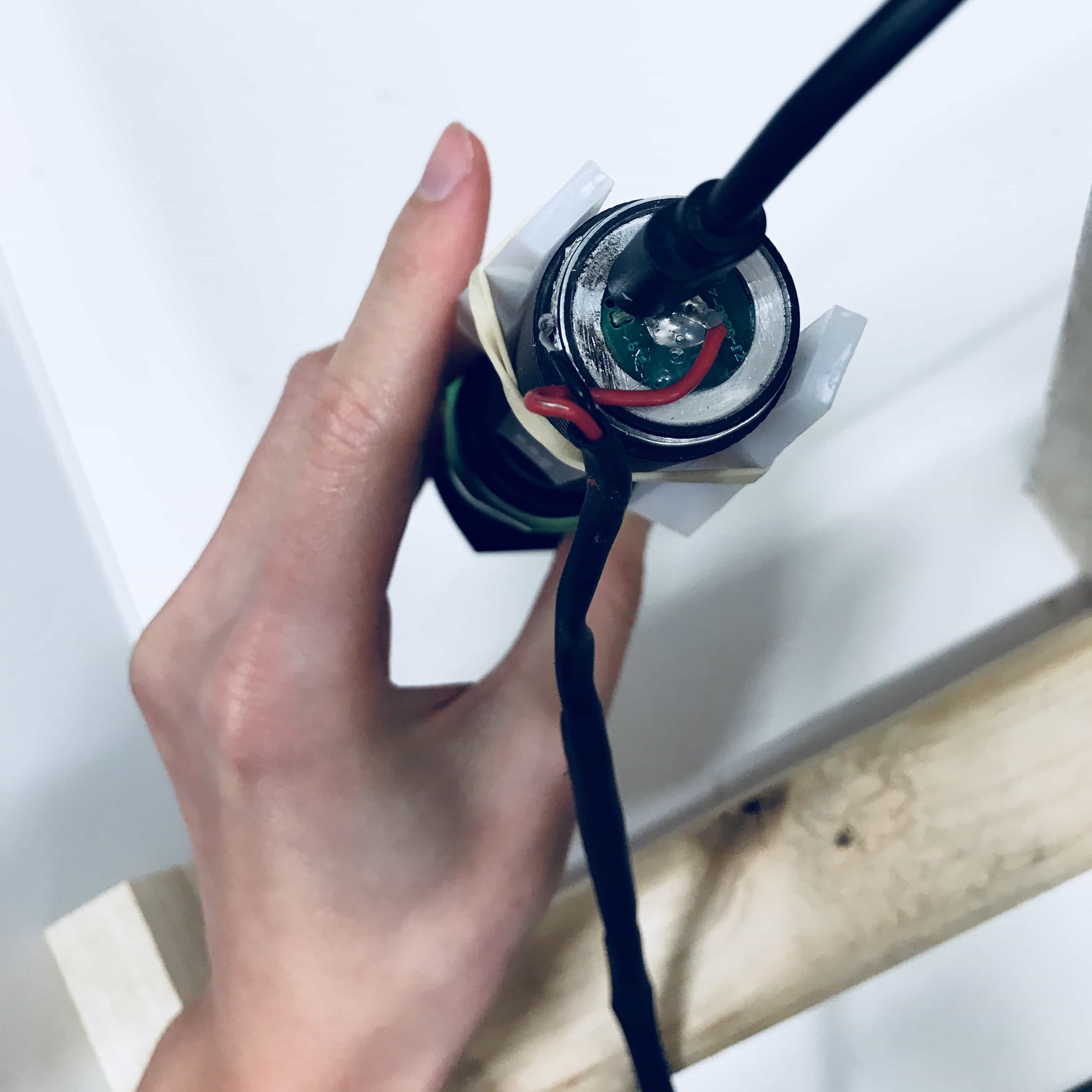
The switch at the bottom of the UV torch light is just linking the center and the circular parts together to turn the light on and off. So I Extened the two parts out and used a MOSFET to control its on/off.
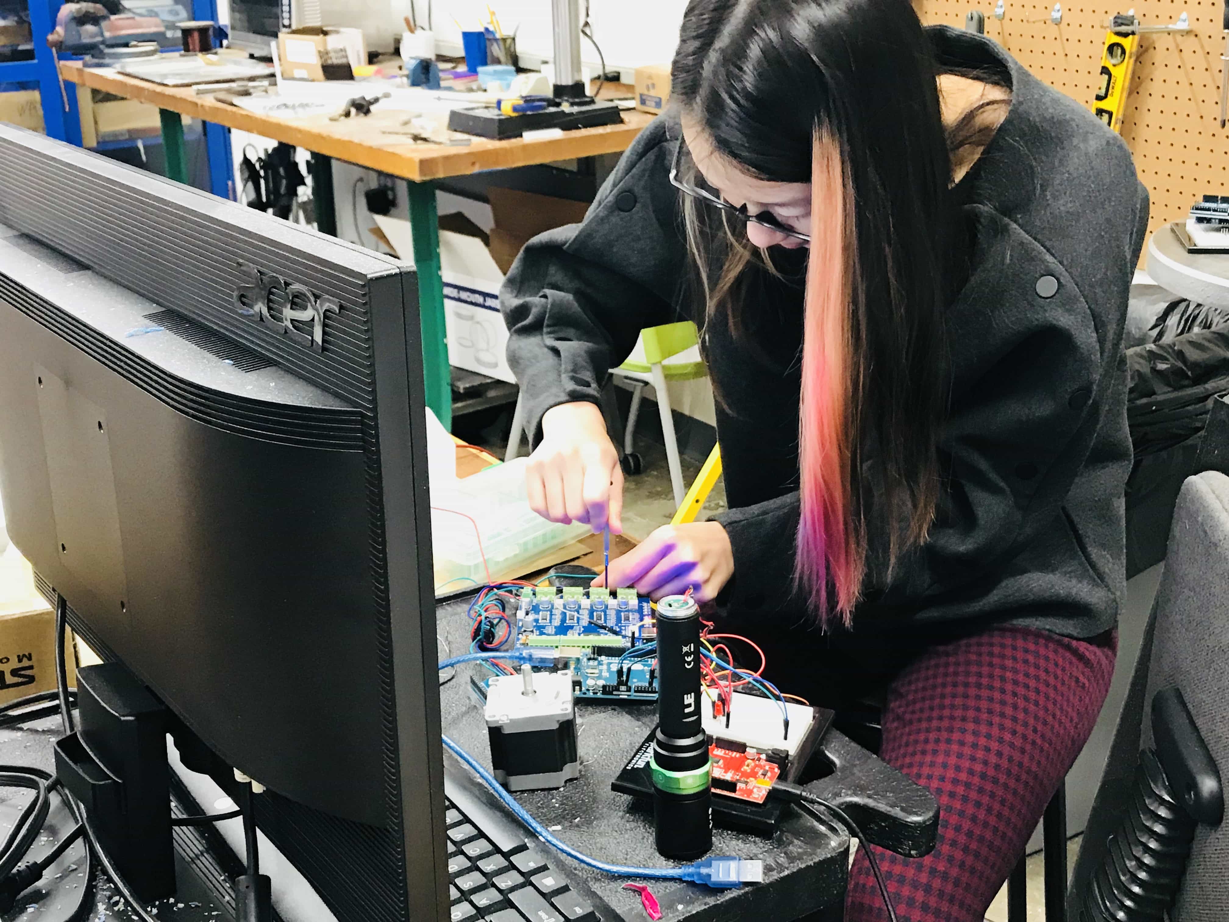
Our machine only has motor on X and Y axis, so we use the movement of Z axis to control the light. The idea is to turn on the light while "milling", and turn off the light while jogging. That means, when Z changes, the light toggles. At first, the Z axis output also changes together with X and Y axis. Later we found out if we put them into "only turn on while moving", they won't affect each other. We used a large resister (not a beautiful solution) to reduce the current coming out from the 24V Z axis output. We smooth the signal with a capacitor and in the code.
Machining
We are using Rhino to view the files and select vectors to export. We are treating these cuts as a series of 2D objects, rather than one 3D object. So, we import 2D vectors into VCarve, and then specify the Z component of different toolpaths within the vector design.
For example: for a clamp, the outline was milled as a 2D path, at material thickness (9.92mm); the lower edge was milled at 1.5mm, as a pocket; the middle was milled at 2mm, as a pocket.
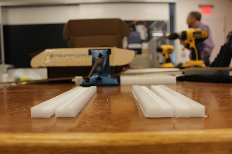
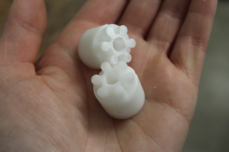
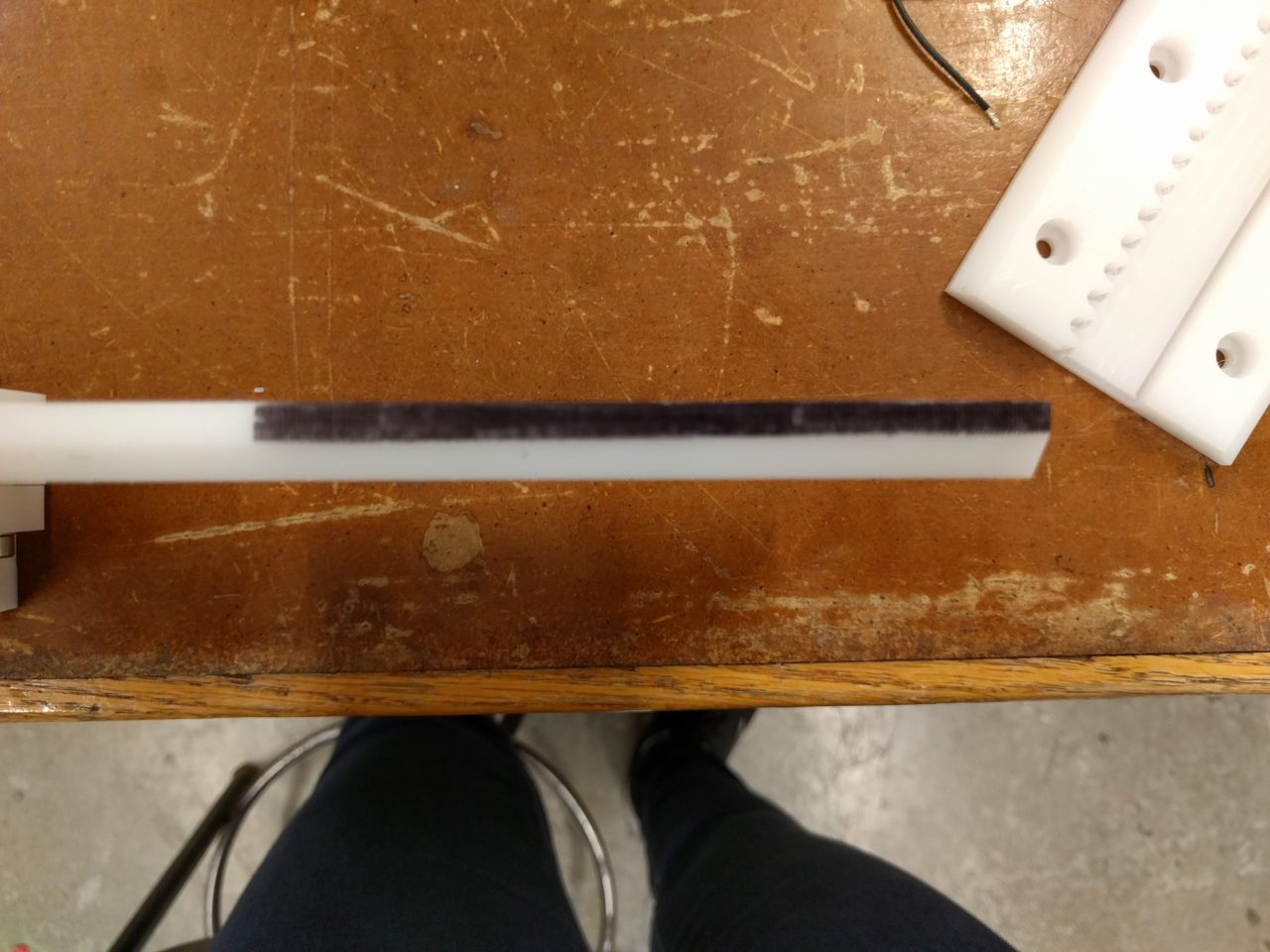
Making these toolpaths was a time-consuming process, and easy to mess up. We started with milling these two clamps, and the first cut of these two clamps was unsuccessful, because the outline toolpath was milled inside instead of outside the vector (see too-small clamps on the left, compared to correct clamps on the right). But with the second cut, a new problem arose: the cut didn't quite go through the material, either due to variation in the material thickness, the sacrificial layer, or maybe it wasn't zero-ed well. For pieces like these, post-processing with a knife was required.
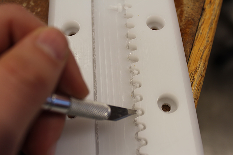
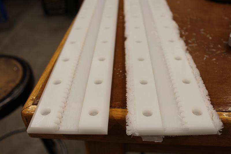
The first axis had come out pretty well, though a bit got broken in the process. However, the teeth weren't quite cleared out, as they were run with a profile rather than a pocket toolpath, and so we ended up clearing them out with an Exacto knife, and changing the file to make the teeth a pocket cut. Because the other bit was broken, we ended up using a different bit with more flutes for the second axis.
The second rack tooks ages to mill, because there were 8 different toolpaths - one at a time, because the too-fluted bit is getting gunked up and needs cleaning in between runs, and we are using four different bits - and it is doing a million runs on the tooth pockets.
We milled the pinions out of Delran, a harder material. The Delran is thicker (19.9mm) and the finished pinions will fit into the teeth of the rail rack. Laying out the toolpath took a long time - it was tricky to measure the distances between points in Rhino, and then we ended up creating circles for the toolpaths of the indicator holes (on the outside of the pinion). We made a larger circle, and created a path between the teeth of the pinion and that larger circle, in order to accommodate the size of the bit.
One of the problems was that the pinion has very fine parts (the teeth), which cannot be cut all the way by an eighth bit. So we are first doing rough cuts with an eighth, and then a fine cut with a 1/16; and then finally the outside is milled with a one fourth, because we need it to be able to go through all the way (and you don't want a piece with lots of flutes going in too far, it might break).
The cuts went well - in three parts (holes and rough cut with 1/8, fine tooth cut with 1/16, then outline with 1/4). We cut two pinions, as we will have two axis. The pinion fits beautifully in the teeth of the rack.
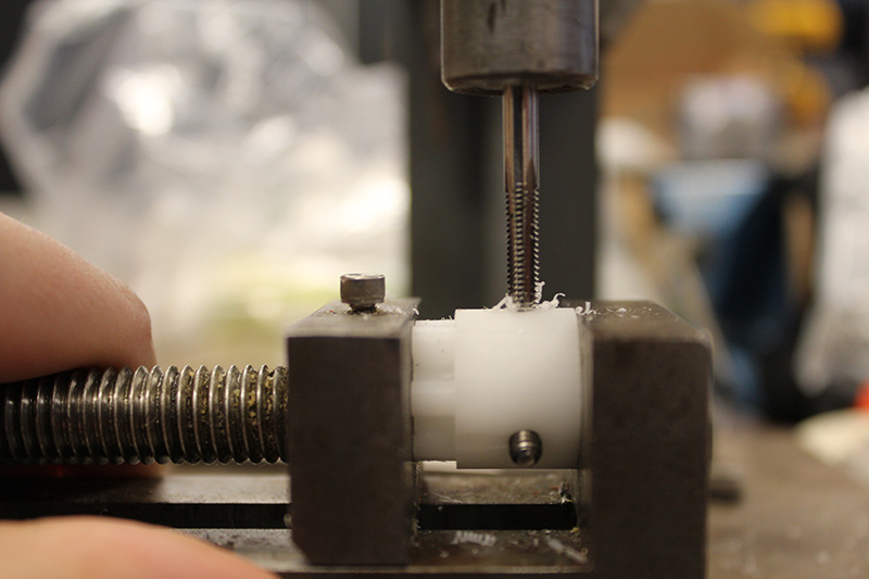
After milling, the pinions required manual tooling; first, drilling holes into the sides with the drill press, and then creating threads within the holes with a tapper, so the 4x8 set screws can twist into the pinion. Finally, a 1/4" reamer on the drill press ensures the central holes will fit the stepper motor arm.
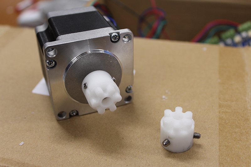
Now the pinions fit onto the arms of the stepper motors! Here's a video of some of the milling, and of the pinion moving down the teeth of the rail rack.
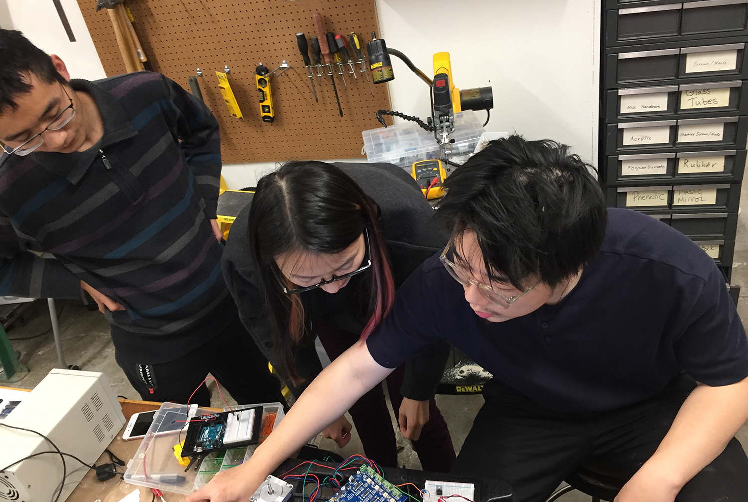
Programming
We began programming with establishing comminication with the tinyG. With a bench power supply we supplied 24 volts (the recomended optimal amount based of the tinyG documentation) and connected to Chillipeppr with the USB port. Next, we wired a stepper to Motor 1 ports on the TinyG, and in Chillipeppr set up Motor 1 to be the X-axis.
We wired up the Y-axis in much the same way and di the same Chillipeppr setup. We did not build a Z-axis and instead wired up a UV flashligh that was both the end effector and the Z-axis.
Joe stopped by and reccommended we add a pinhole filter to the end of the flashlight to get finer resolution. This worked great.
Assembly
This is (in theory) pretty straightforward: there are a bunch of pieces and you put them together. However, in practice, it was not that simple.

We first ran into the issue of not knowing how to connect the two degrees of freedom. We had the parts for the two axes independently, but we were unable to connect the parts in a way that didn't affect the motor and was square. We therefore decided to mill the part from Jake's original design that has the two axes combined in one piece. Although this seemed somewhat simpler, it also made it nearly impossible to hold the part level enough to adjust the tolerances for both sides. We eventually managed to do so, after much trial and error.
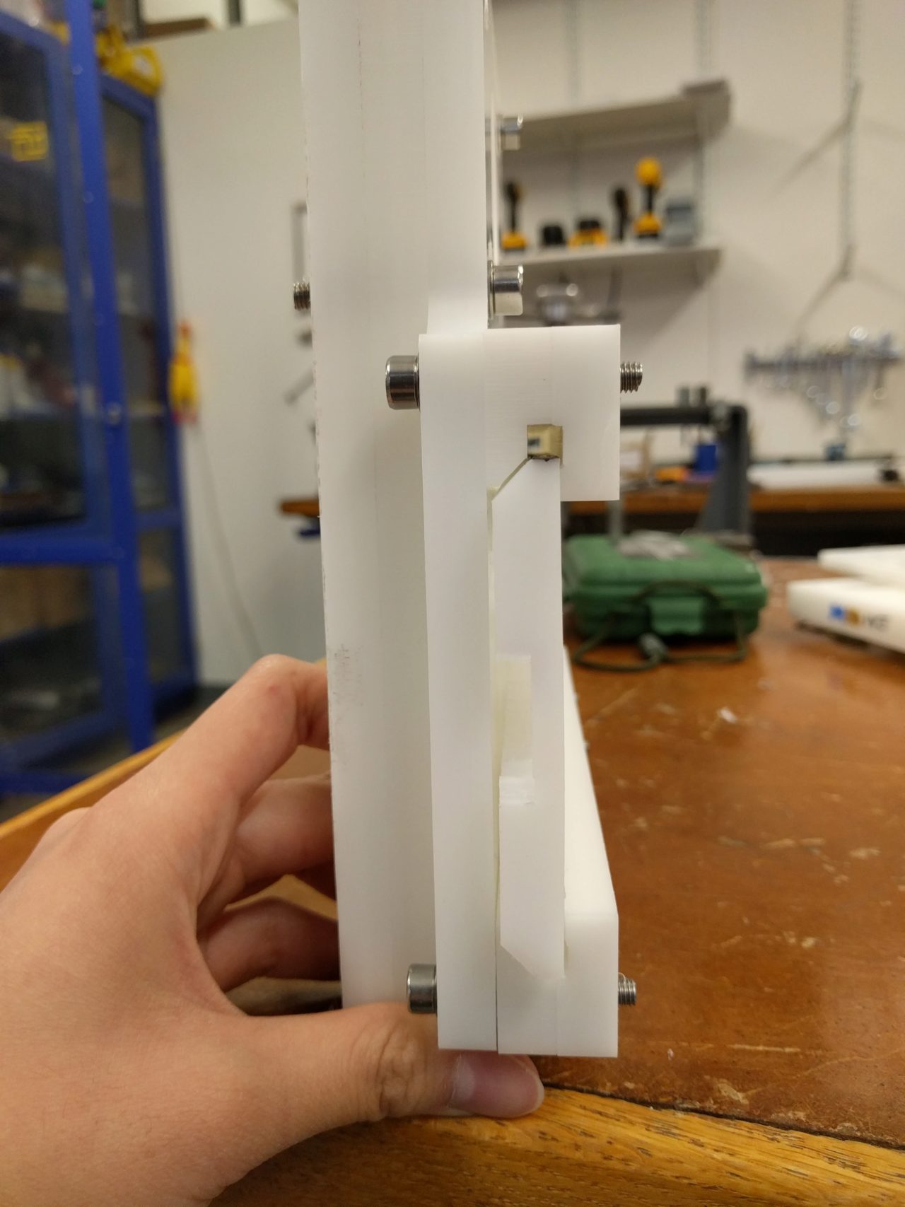
Another issue that we ran into was that the rack wasn't exactly the same thickness along the entire length. Rob helped identify the issue that the sacrificial layer on the Shopbot was a little off on one side. This resulted in the rack being super tight at one end and a bit loose at the other end. However, it was still within our tolerances, so we did the best that we could to split the difference.
One end was too loose.
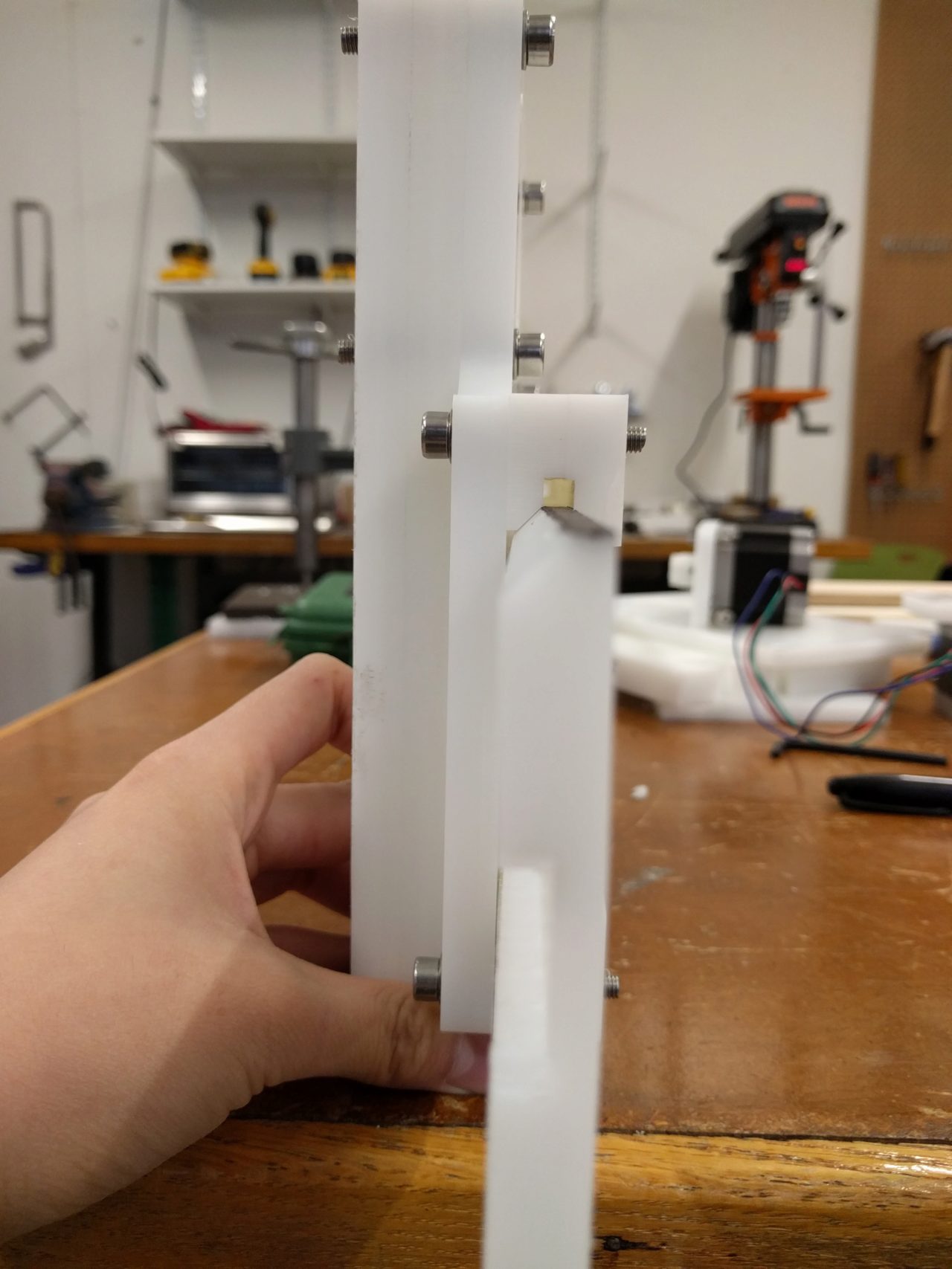
The other end was too tight.
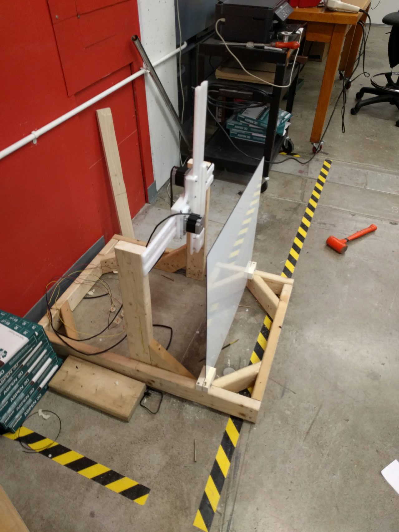
We made the frame out of 2x4s -- some good old fashioned fabrication. It turns out that framing (especially with wood) is a non-trivial problem. First, we made a simple rectangular frame:
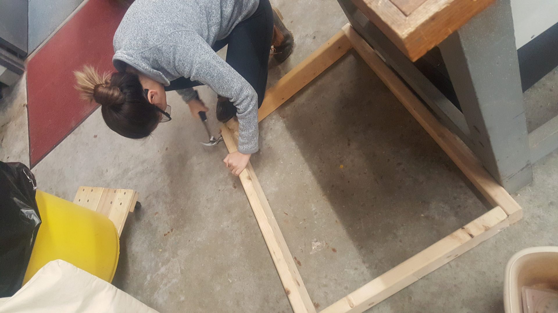
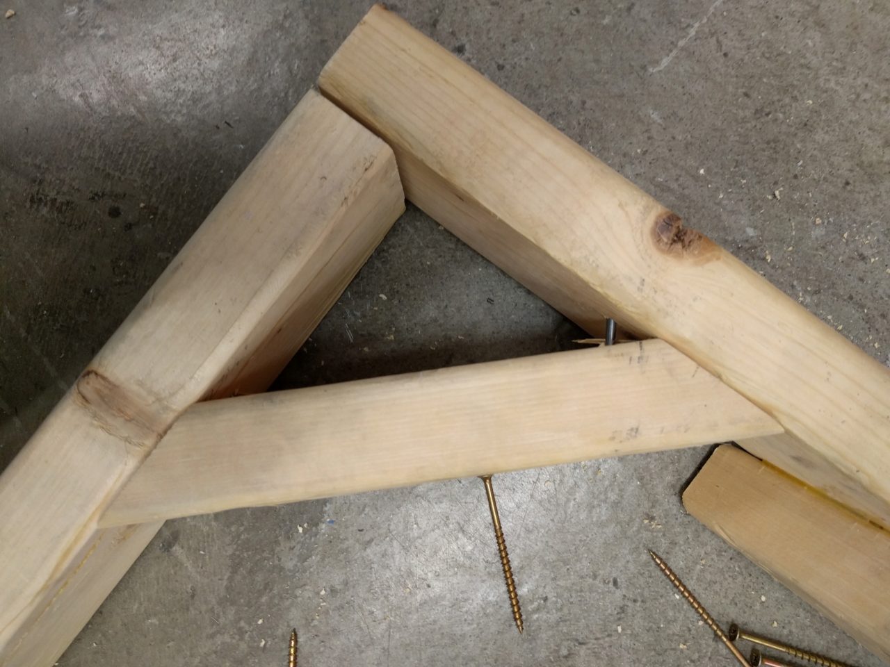
But it turns out this doesn't stay very square. The solution? Brace it! (And when you're done with that, add the vertical supports for the actuators.)
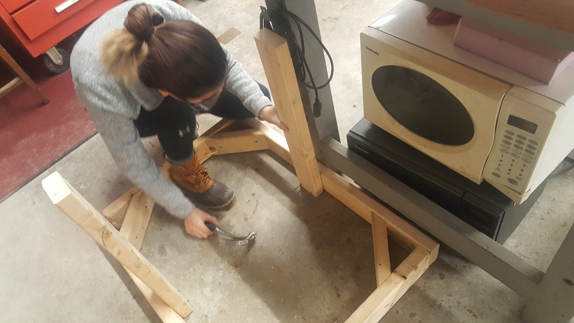
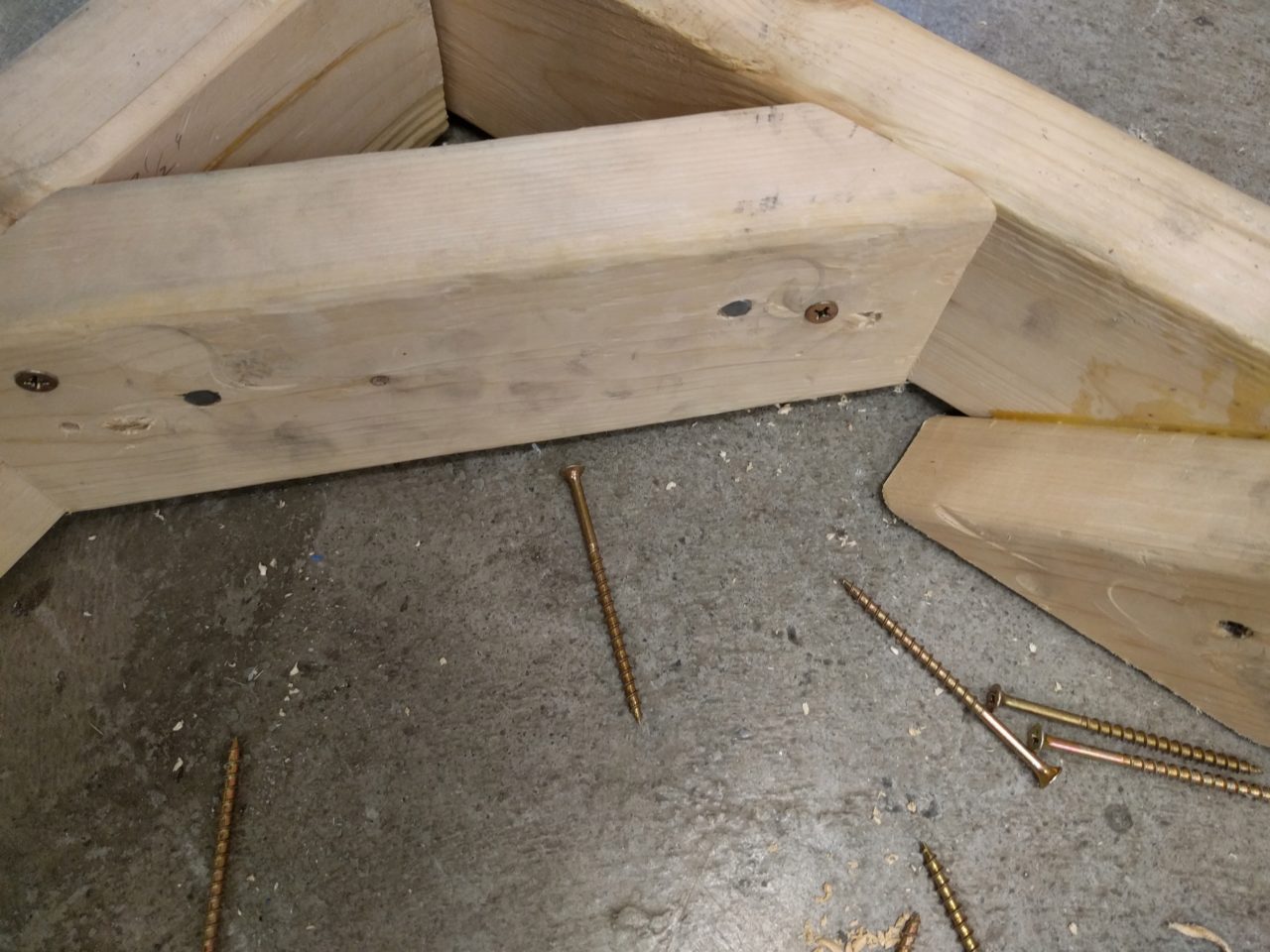
We started by using nails to hold the frame together, but this turned out not to hold very well, so we added screws as well.
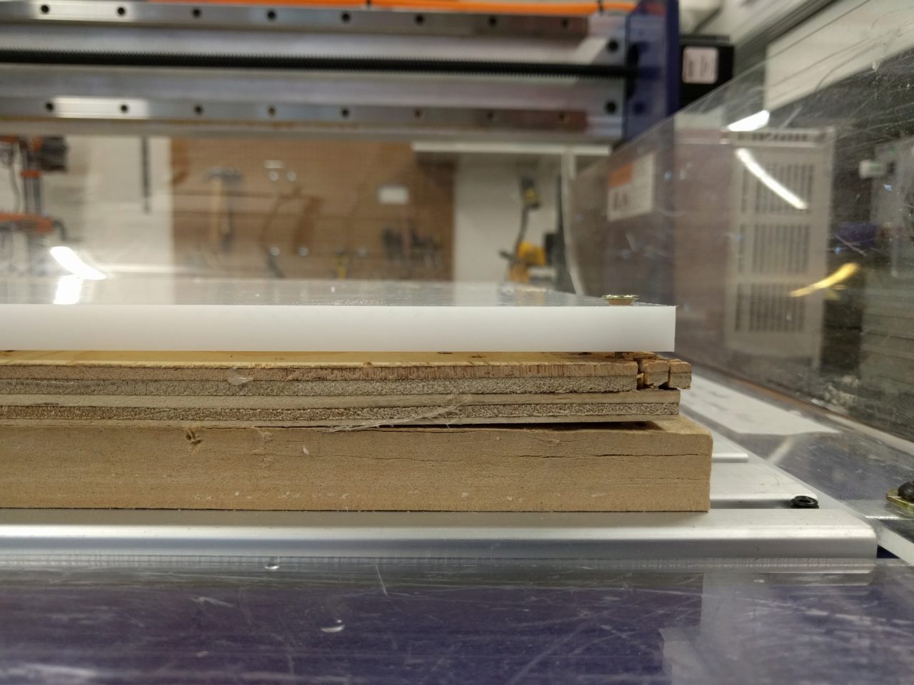
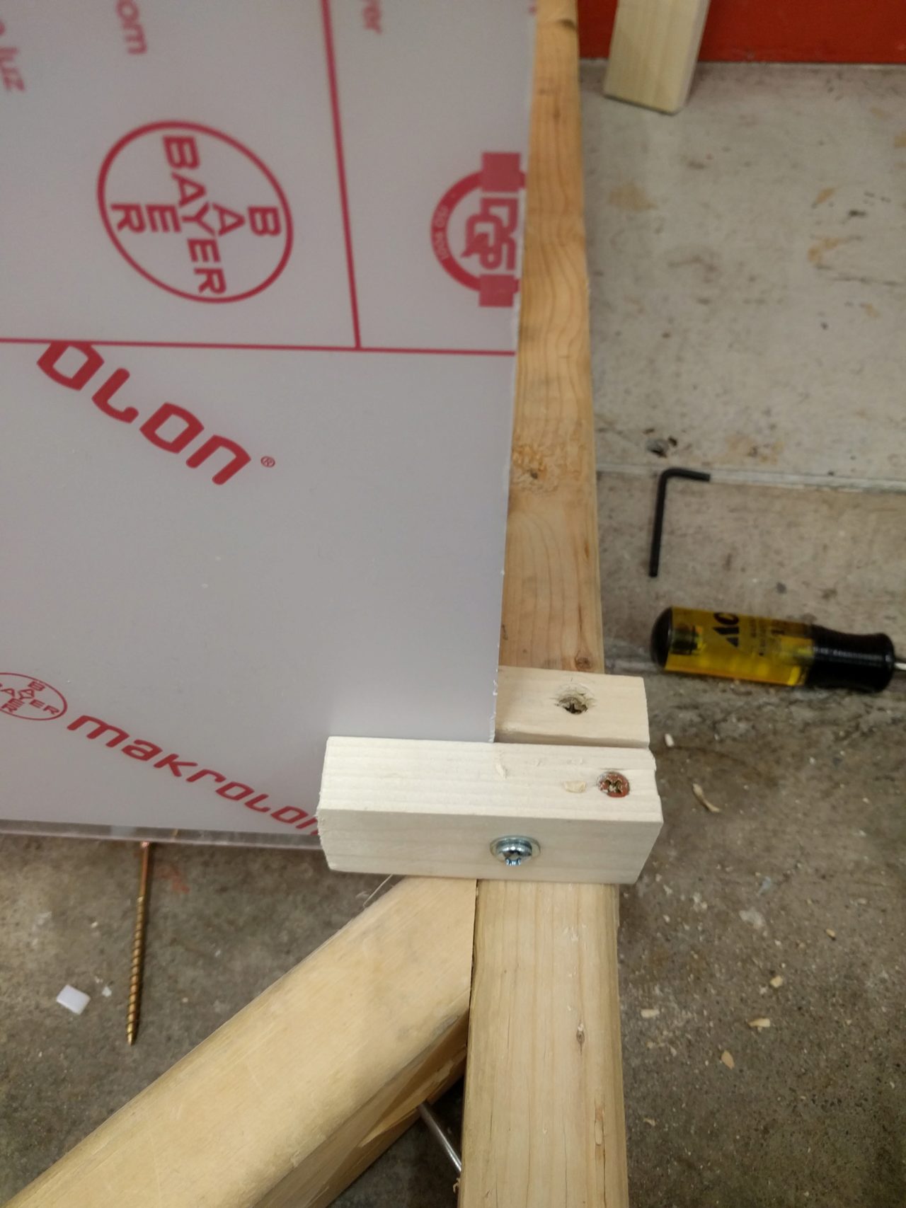
When adding the acrylic piece, we cut chanels into the frame, but this was not nearly sturdy enough. We then added two pieces of wood bolted together to sandwich the acrylic on either side. The end result is sturdy enough for our purposes, but still a bit wobbly.
Once we were happy with the rigiditiy of the acrylic piece, we stuck the photo reactive paper onto the acrylic piece and set it in the chanel. Everything looked pretty good.