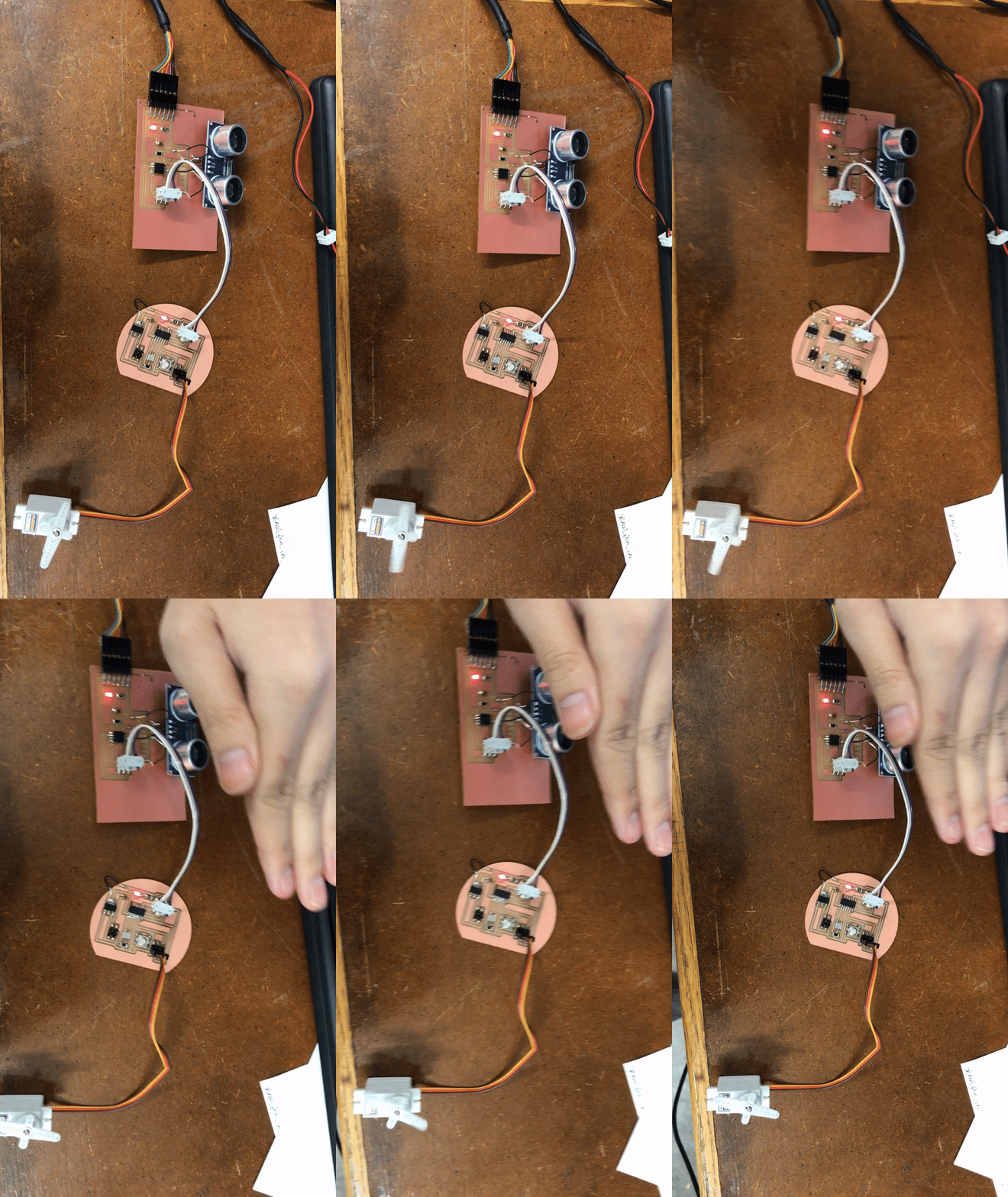
Bus Connection
This week I decided to network my input and output device boards, therefore network a distance input with a servo output. I originally wanted to network using an IC2, master slave connection since I thought it better reflected my final project of a panoramic time lapse mount (lets be real, the master slave connection between flashes and lights in the camera world shadowed my judgement.) But after researching the connection, I realized that a bus connection was simpler and would do the same job. I was too lazy to redesign the board to include a 2x2 pin for the bus connection, so I utilized the 2x3 ISP header I used to program the board.
Simple Connection
I originally programmed the network for the distance, servo connection to work as follows: The distance device will constantly write out what distance it is currently writing. The servo in turn will first move to hard coded position 1 before moving to a position correlating to the distance output read in and moving to hard coded position 2 and repeating that cycle. When first programing this, the servo board would move between position 1 and position 2 before being connected to the distance board. After connecting to the distance board, the servo would get stuck at position 1. Using the application week code allowed me to see that the distance device was still giving out correct distance numbers. Thus after lots of debugging, I realized the servo board was getting stuck at reading in the characters from the distance board. After lots of research, I realized the pin I was using on the servo board as my input pin was the RST pin. I changed the pin to the SCK to read in the inputs from the bus and did the same for the distance board. After changing the pin, the servo correctly moved to the middle position corresponding to the distance read in. I then modified the code to change between a single, pre desginated position and a position that corresponds to the distance networked to the servo board. The code on the distance board is very similar to the code I wrote during application week, with the feature that the board does the calculation between the high and low and outputs a single number value representing the distance. I created a special 2x3 pin header cable that only connected ground, vcc and the sck pin (that I used to read and write on both boards).

The distance board code can be found here and the servo code can be found here
Rotation Speed Based on Distance
After correctly programming and designing a network, I slightly changed my code to be closer to my final project. This time I tried to incorporate the button on the servo board. I coded the board so if the button is clicked it will start a rotation, the time of which will reflect the distance read in. The button was straightforward, but finicky to incorporate. When the button is released, the servo board will read in the distance networked through the bus by the distance board. Based on this distance it will calculate a wait time between movements, which will change the speed of the rotation. After that it will do the rotation with the appropriate wait time.

The distance board code can be found here and the servo code can be found here