Example Board
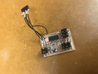
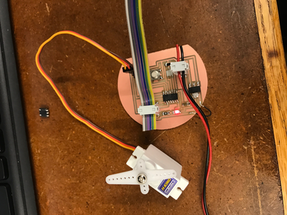
This week I decided to make a servo output that will be used in my final project to turn a camera to make a panoramic time lapse. To start off I wanted to make the example board given on the website just to make sure I understood how the servo worked. After several attempts to mill the board with a varity of mistakes, I made the board exactly like how it was on the site. But I was unable to program the board the the regulator would heat up extremely every time I pluged it in. After doing the whole process and making a second board but still having the exact same issue I went to Rob for help. He informed me that the regulator supplied in lab was different than the one in the example. I hacked together the proper regulator confirmation using wires. Then I was able to program the board. After tickering with the example code, I used a for loop to make the servo turn in circle evenly instead of moving back and forth like the example code..

Desiging a Board
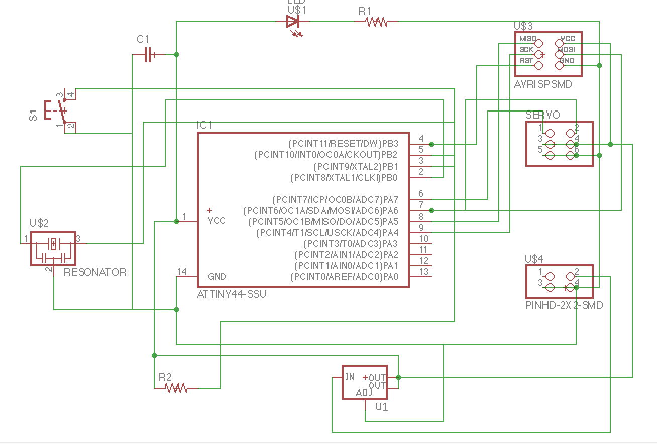
I designed my own servo board in Eagle. I added a button and led and resistor in series as a power indicator to the board. Just like week 5, I used the example board as guidance before adding my own parts. Again, routing the board was a complicated process that took a very long time. After triple checking my connections I milled the board.

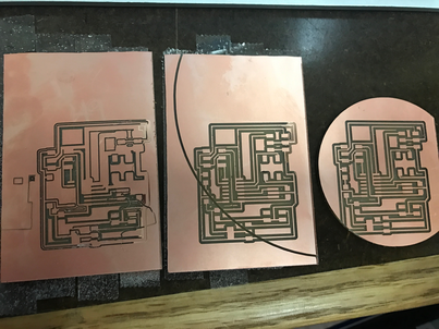
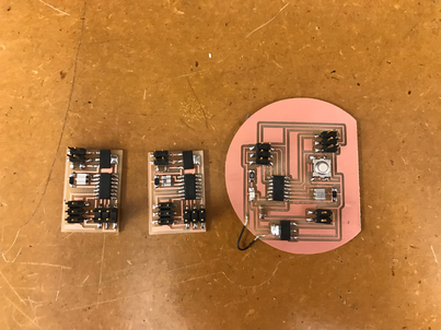
The first board I milled was not taped down properly and moved while milling the traces. On the second board, I forgot that the image was double the size on the interior cut and cut through my traces. On the third board, the origin of the interior cut was slightly off the traces origin and I ended up cutting a corner trace. I decided that was ok and I used a wire to complete the trace. I noticed that some of the traces did not completely cut and used an exacto knife to cut them. I sautered the board and then attempted to program it. It didn't work. It took me a while, but with the help of a voltmeter, I realized my ground was connected to my VCC. After unsautering and resautering several pieces, I realized a very small corner of an ISP pad was connect to a trace. After cutting it I was able to resauter the board and program it.
Programming the Board
After creating the board I programmed it. After using the code I created for the example board I built off of it to incorporate the button on my board. I incorporated parts of the button code from input devices into my code. At the end, I coded and programmed the board so if you click the button it will start an even rotation of the board.
The code of this week can be found here.
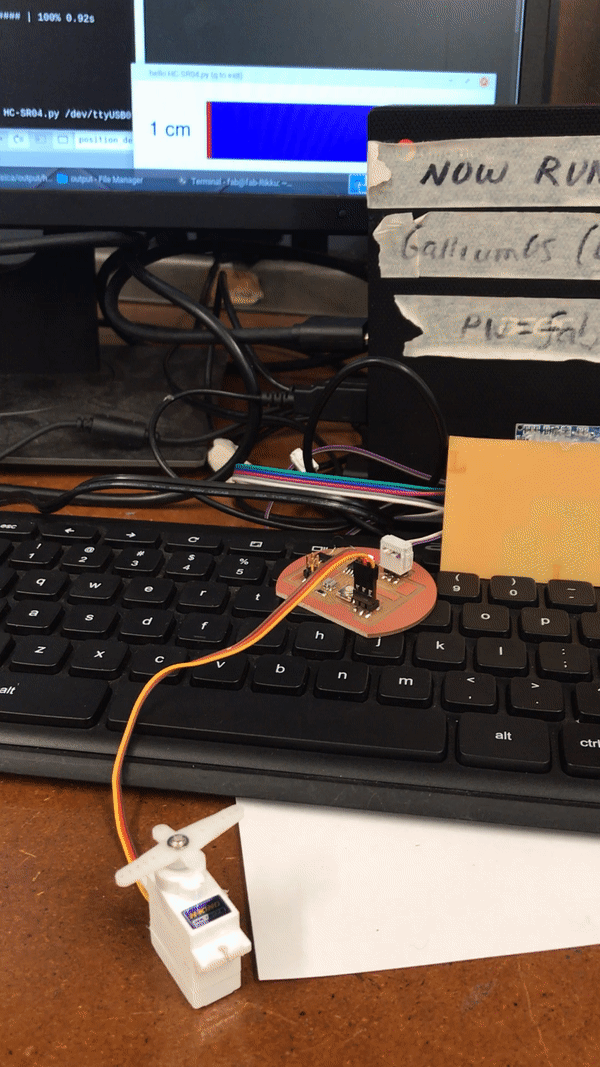 PS. This video is from networking week, because I forgot to take one during input week. But the servo fuctions exactly the same, but with a hard coded speed value.