A-Maze-ing
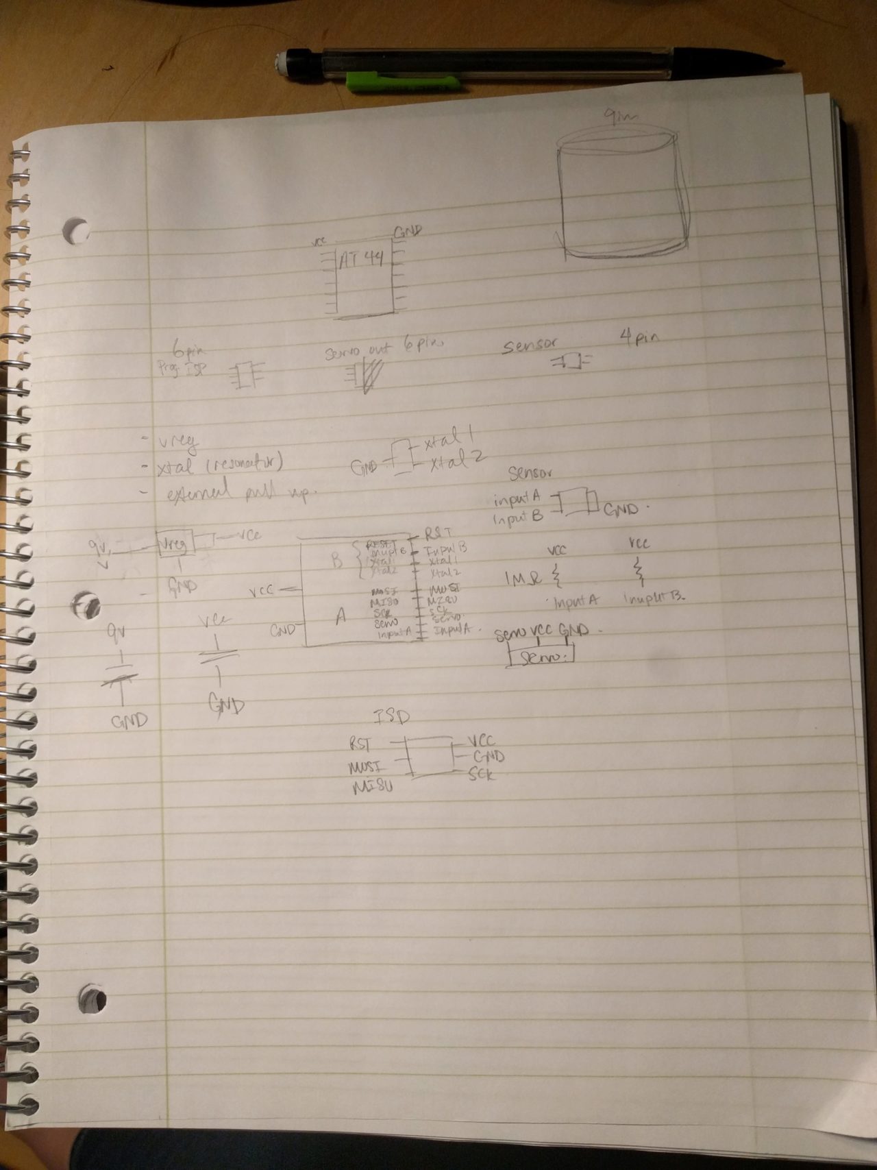
I really like puzzles and games, so I want to make a kind of maze made up of concentric rings that spin independently of each other and alter the difficulty of the puzzle. I made some drawings to fully develop the idea and have a working design in OnShape. I also attempted to use AutoDesk to make some designs, but it was difficult to work with some of the constraints, so I switched to OnShape and it's been working pretty well.
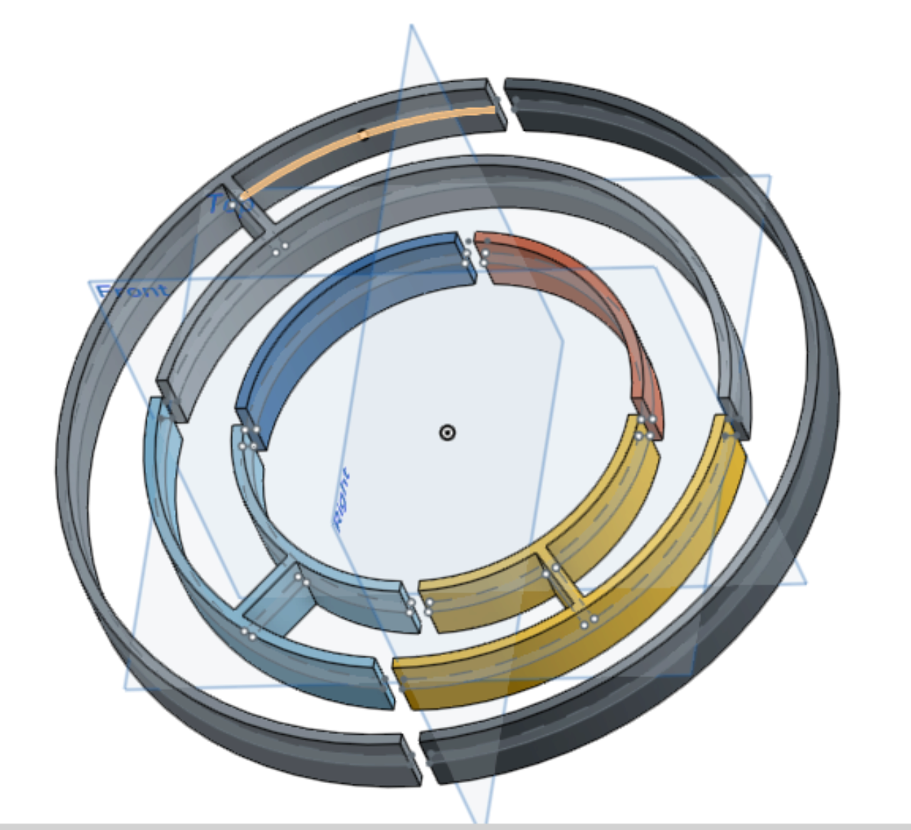
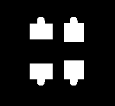
Above is some simple CAD work I did in OnShape to flesh out the idea. Ideally, I would have concentric rings that look similar to the above design and could nest inside the space in the middle. The different rings would rotate independently of one another and result in a different maze puzzle by aligning the different possible routes. I'm currently struggling because it looks like the maze will not be very difficult if I want to make it have may different maze options. My boyfriend Will suggested that turning this into an alarm clock might be a good idea.
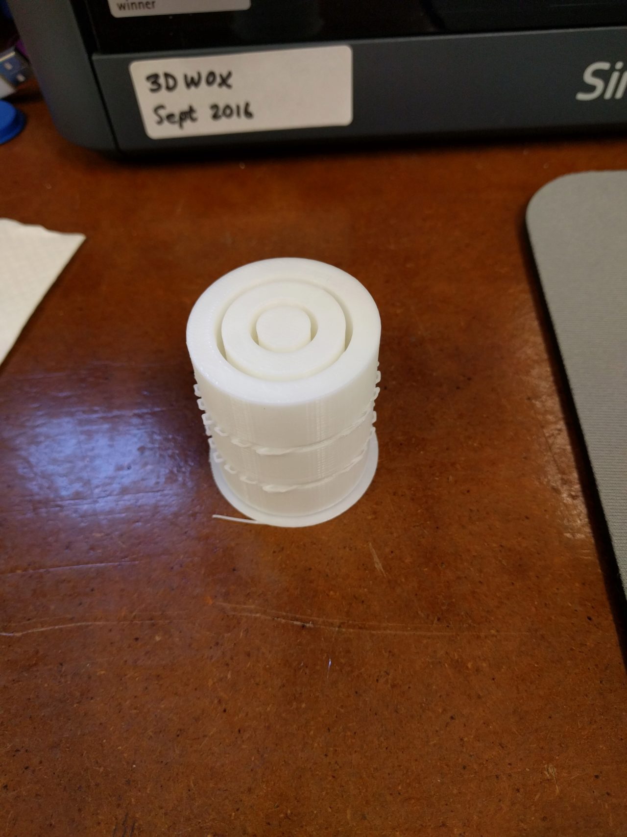
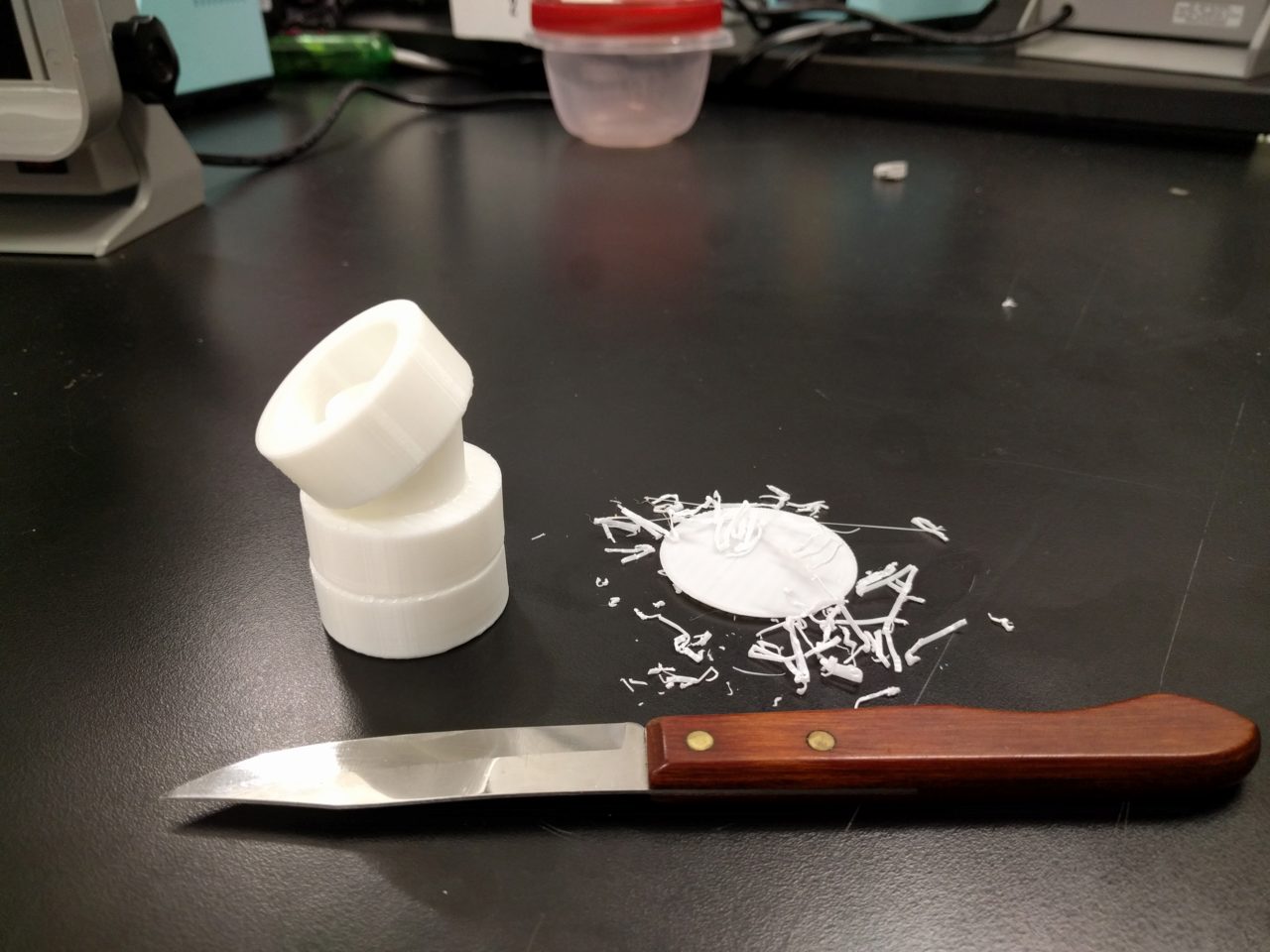
For the 3D printing week, I designed a possible axle prototype that would allow you to spin different levels independently. Although it only has 3 layers and the dimensions need a lot of work, it taught me a lot about what I can do with 3D printing. A better option would be to 3D print the maze parts and make the axle through some other means. I'm currently not sure on the maze design, but I will work with that next.
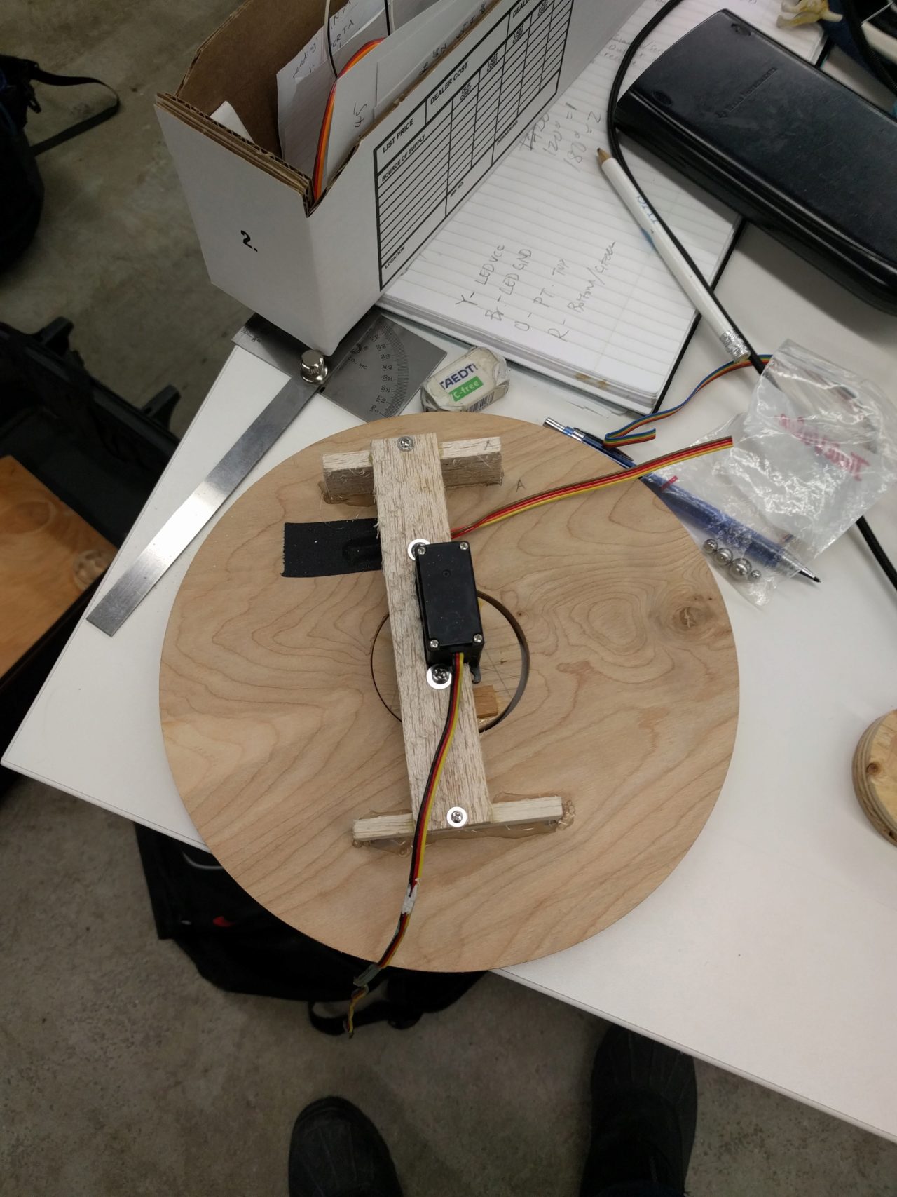
For output devices week, I managed to get a servo working. The next step will be to mount the different maze parts on top of it, as well as figure out a way to get different servos to control different parts along the same axis.
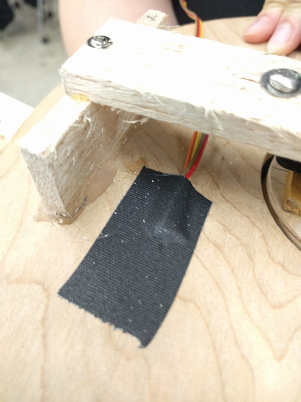
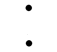
I struggled for a long time trying to figure out what type of input device I could use. I thought the capacitive touch sensor was really cool, so I tried to make a touchpad that respected the symmetries of the maze. You can see the final result with that here. However, since I really wanted to use a physical ball bearing (something nostalgic about that), and the ball bearing was not going to be grounded, I was concerned that the signal would be unreliable or too weak to sense. I spent probably far too long trying to create a sensor where the ball actually had to contact two electrodes to bridge a switch. This was very finnicky, and the V-groove that I prototyped on did go very well with the rest of the style of the end result. I decided to come back to this later.
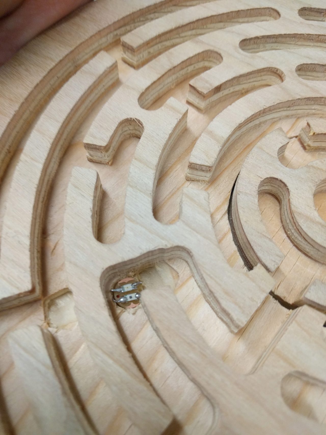
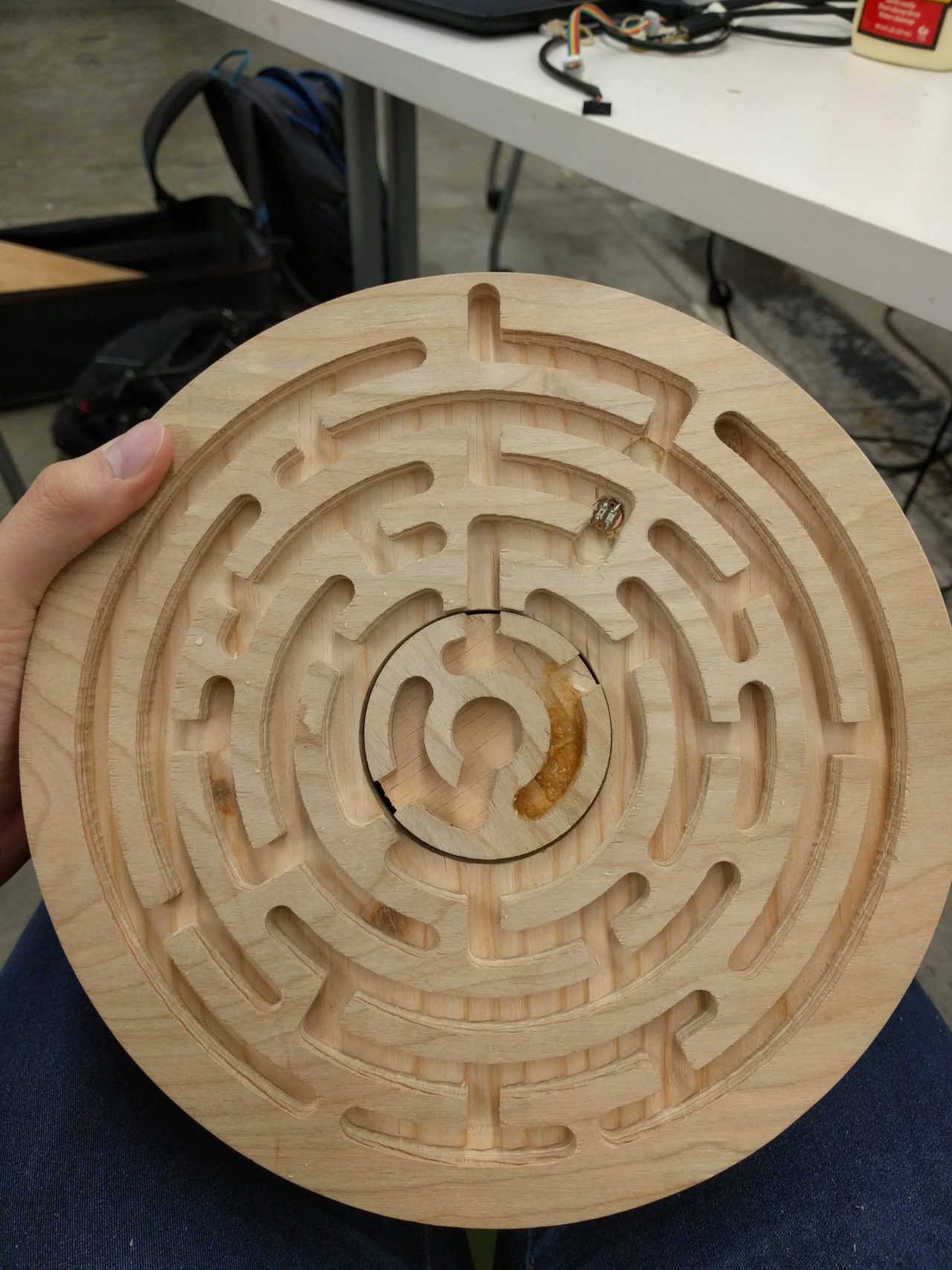
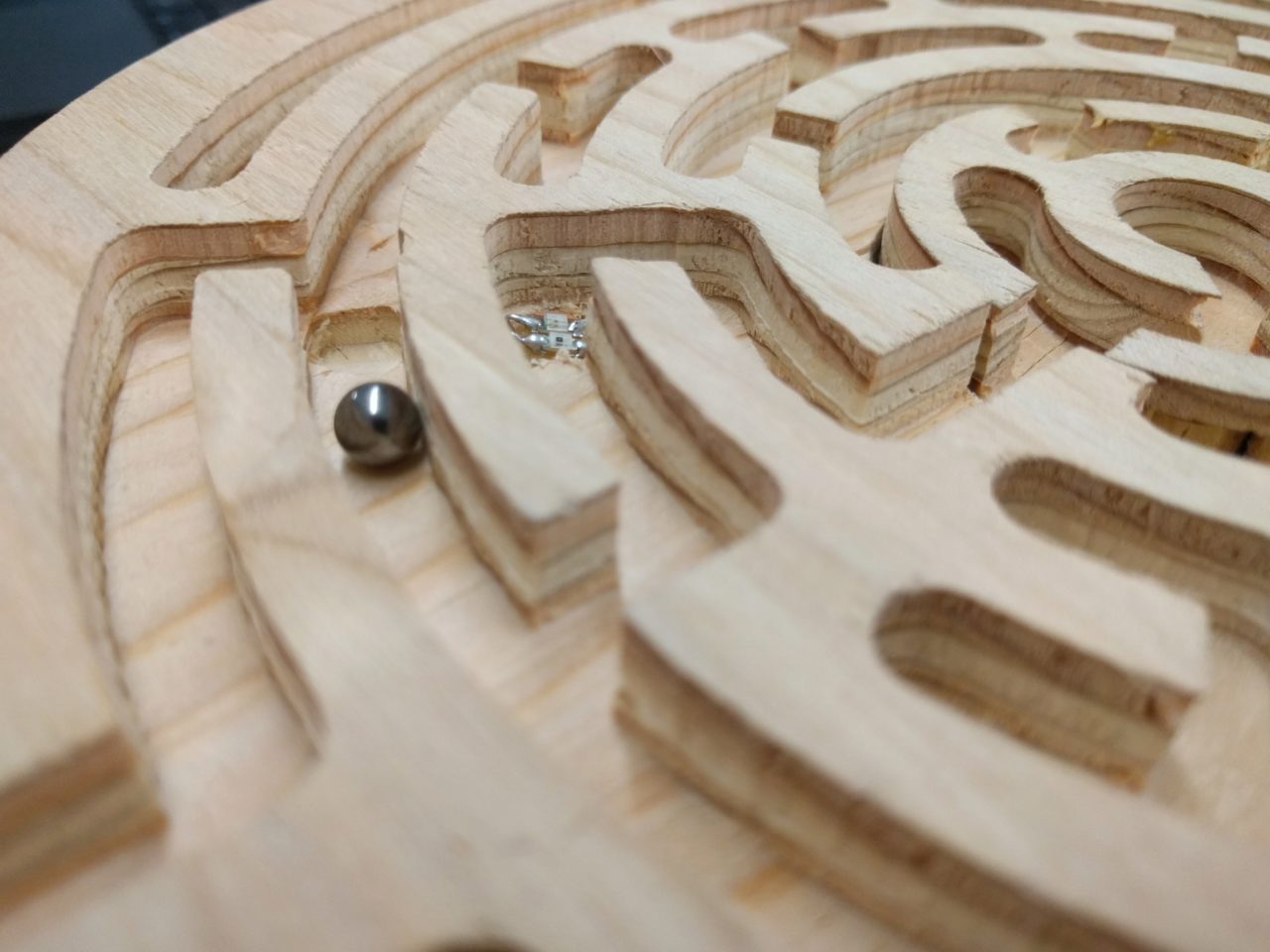
I used Inkscape to draw the vector for the paths of the maze, with much help from Will. I then used Onshape to turn them into maze plates. At this point, my maze design had simplified from having multiple concentric rings to having just two rings and the middle section forcing you to take different paths. In discussion with Will, he suggested that it would be interesting to have a maze that, due to the center changing orientation, forces you to take more paths than you initally thought. As a result, the center of the maze has 3 exit, but only 1 of them leads to the goal. By controlling which of these channels you have access to, you can force the player to go to at least 3 separate paths. An important feature that forces this is having one way channels.
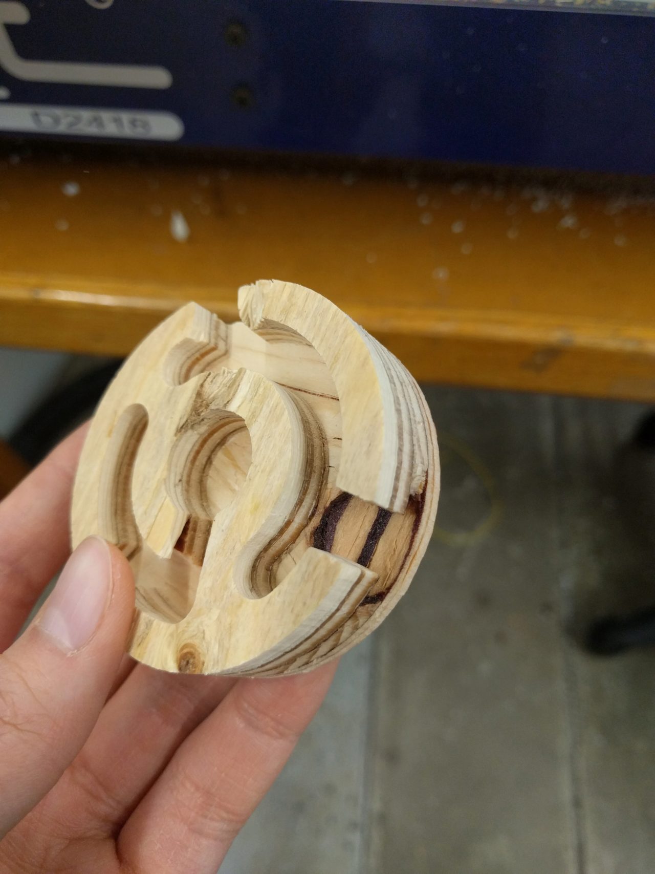
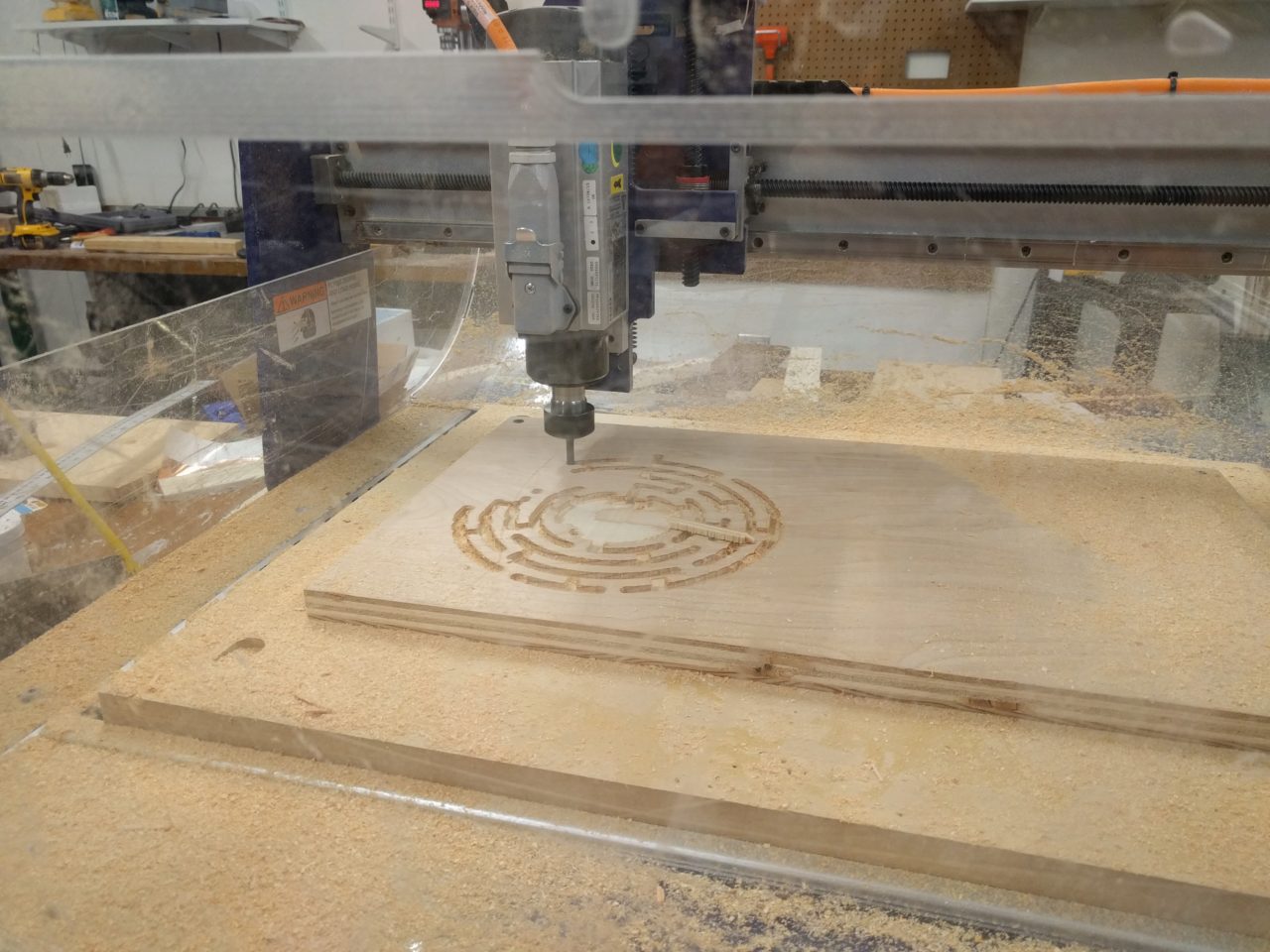
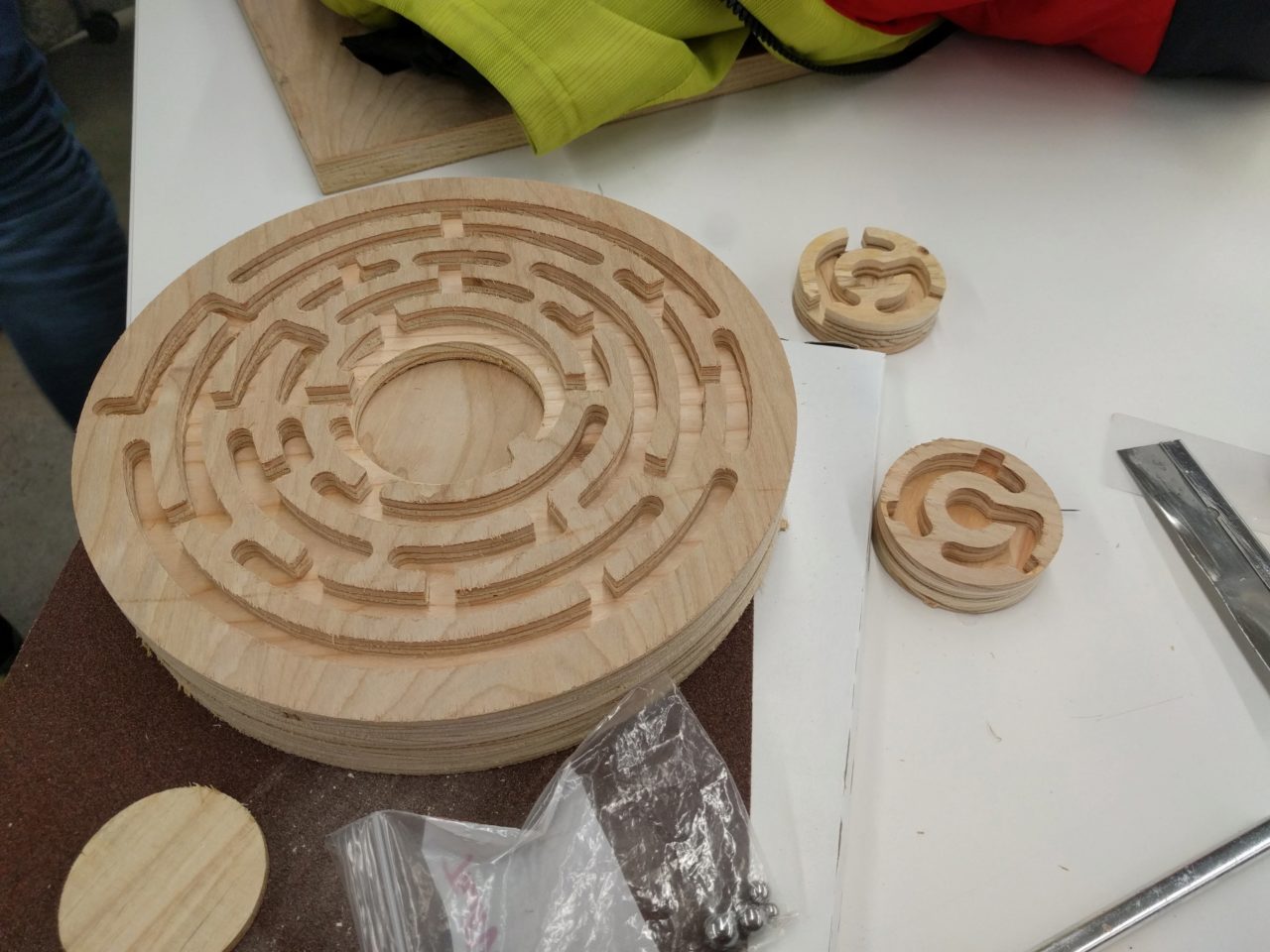
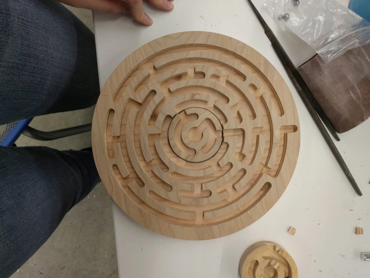
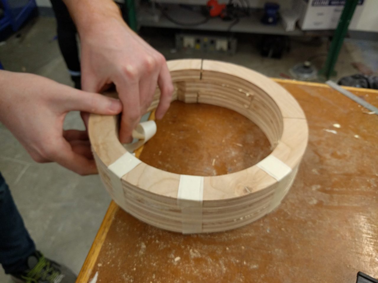
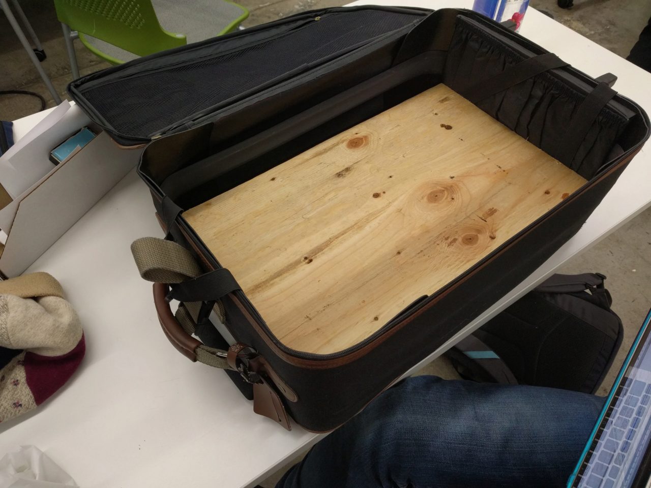
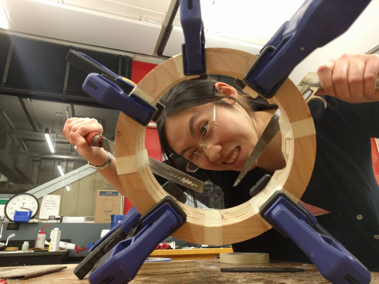
I milled the maze plates as well as the sides and bottom from 2 sheets of 20in x 12in furniture grade birch plywood (donated by Will). The one way channels work quite well, and were fairly easy to mill. When I was prototyping the servos for use in my original maze design, the different part could turn relative to each other. But in my new design, the main plate remained fixed whereas the only the center moved. Therefore, I had to change the design a bit and re-mill the center piece. Unfortuately, I suppose I didn't tighten the collet tight enough, and the milling slid lower than expected during the job. I was luckily able to catch this before it broke the end mill, but it did leave a nasty mark on my center piece, which I filled with wood glue and sawdust. It does leave a blemish on the maze, but it doesn't affect gameplay much.
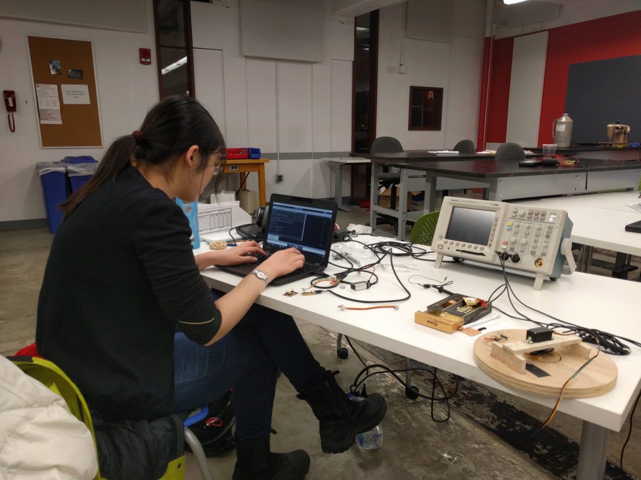
The servos were relatively easy to program, following Neil's example code and changing the PWM using the datasheet for the associated motor. I ended up using the HS-322HD Servo (~$11-$32) because it has the 180 degree range that my piece required. I calculated values close to my expected angle and did some trial and error to tweak the final lineup. Rob mentioned that this might be necessary since not all servos have the exact range specified on the datasheet. The input device was far more difficult to prototype. Following my previous series of failings with attempting to sense a metal ball moving quickly in a thin channel, I followed Dixon, Julian, and Rob's advice and used a phototransistor. My first attempt was an attempt to re-produce Neil's simple phototransistor, and although I got it to work, it was very sensititve to ambient light and the orientation of the maze. Rob suggested that I try somethng with the synchronous detection phototransistor instead. That way, even though the ambient light is changing, calculating the difference between when the LED is on, vs when it is off and then averaging provides better readings for the ambient light.
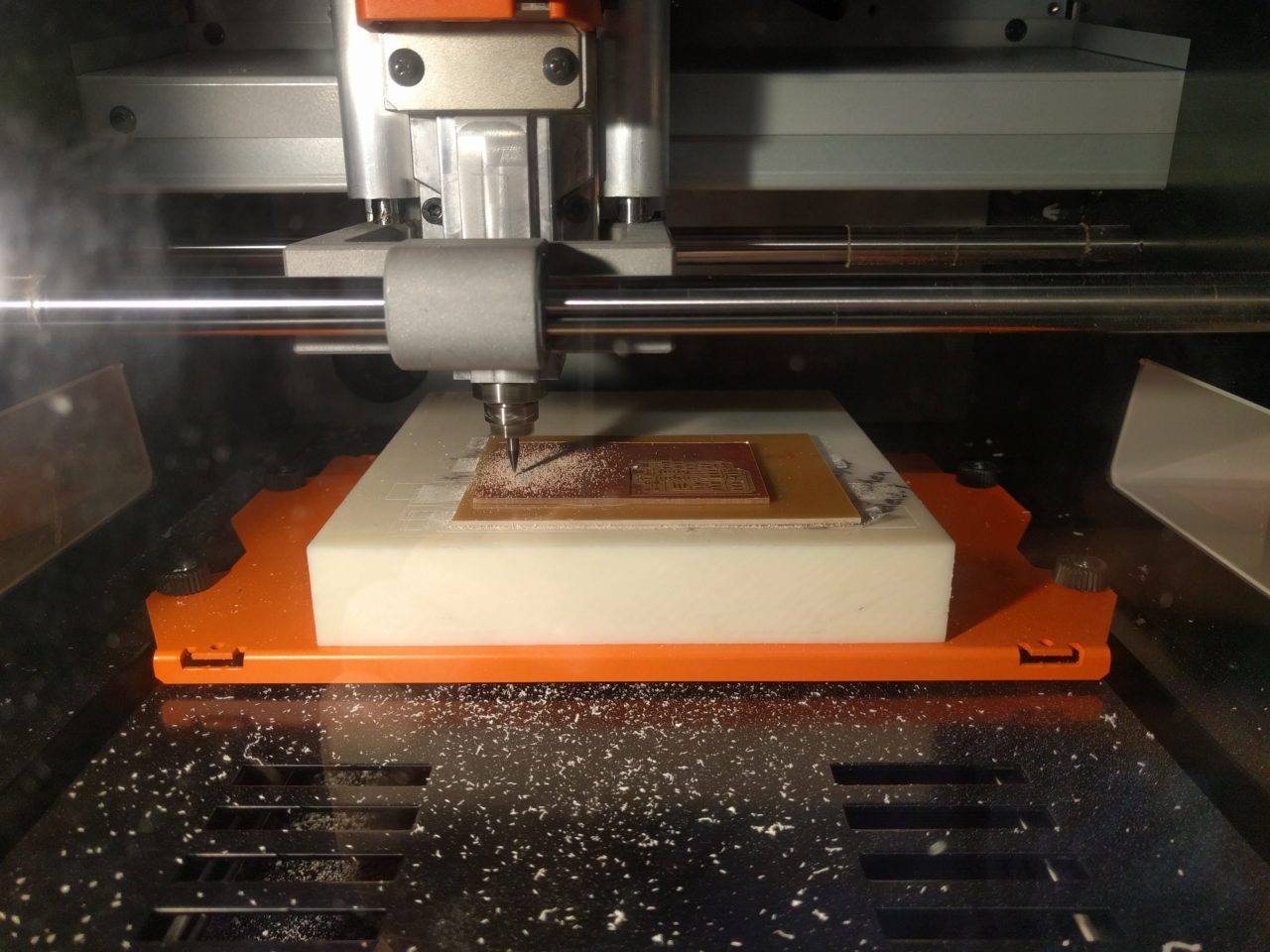
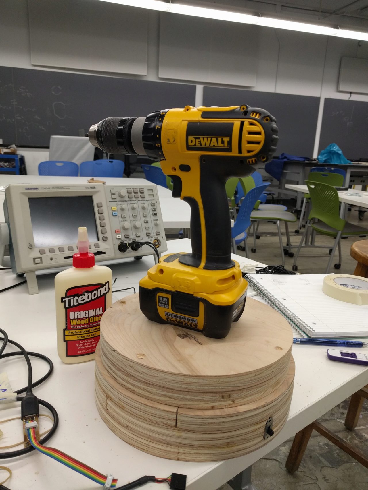
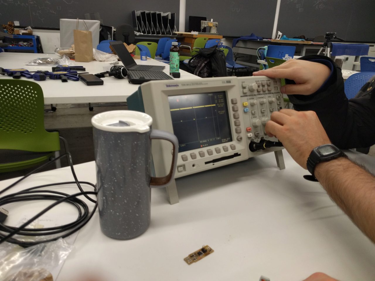
I re-produced Neil's example and then made my own sensor part for use directly in the channel. Early tests were promising and showed high sensitivity but also few false positives. Once I had working input and output devices, I tried to make them communicate with each other. Using Neil's hello.bus code as an example, I programmed the servo to turn to the desired positions on the associated keypress in term.py. This later because very useful as a debugging tool and when I was asking for help. Julian also showed me how to debug using an oscilloscope to actually see the signal. I was stuck for a long time trying to figure out how to get the boards to communicate over serial, but then it was suggested that I didn't really need the board to communicate using serial, and that I really only needed to send the state of the sensor (i.e. is ball present) to trigger the servo motor. Will was very helpful and explained and walked me through the details of what I wanted to to do.
A quick video when I got the sensor working
In quick summary:
- What does it do? In short, it is an adversarial tilt-ball maze that at the present moment simply prevents you from completing it as quickly as expected. A simple modification might prevent you from ever solving the maze (without breaking the rules).
- Who's done what beforehand? Many people have incorporated mazes into there final project, such as Katie Levine's joystick controlled Labryinth maze and Matt Pearson's Electromagnetic Maze, but none of them so far seem to be adversarial. On a more basic level, plenty of people have used the servo motors to position devices and the phototransistor for input.
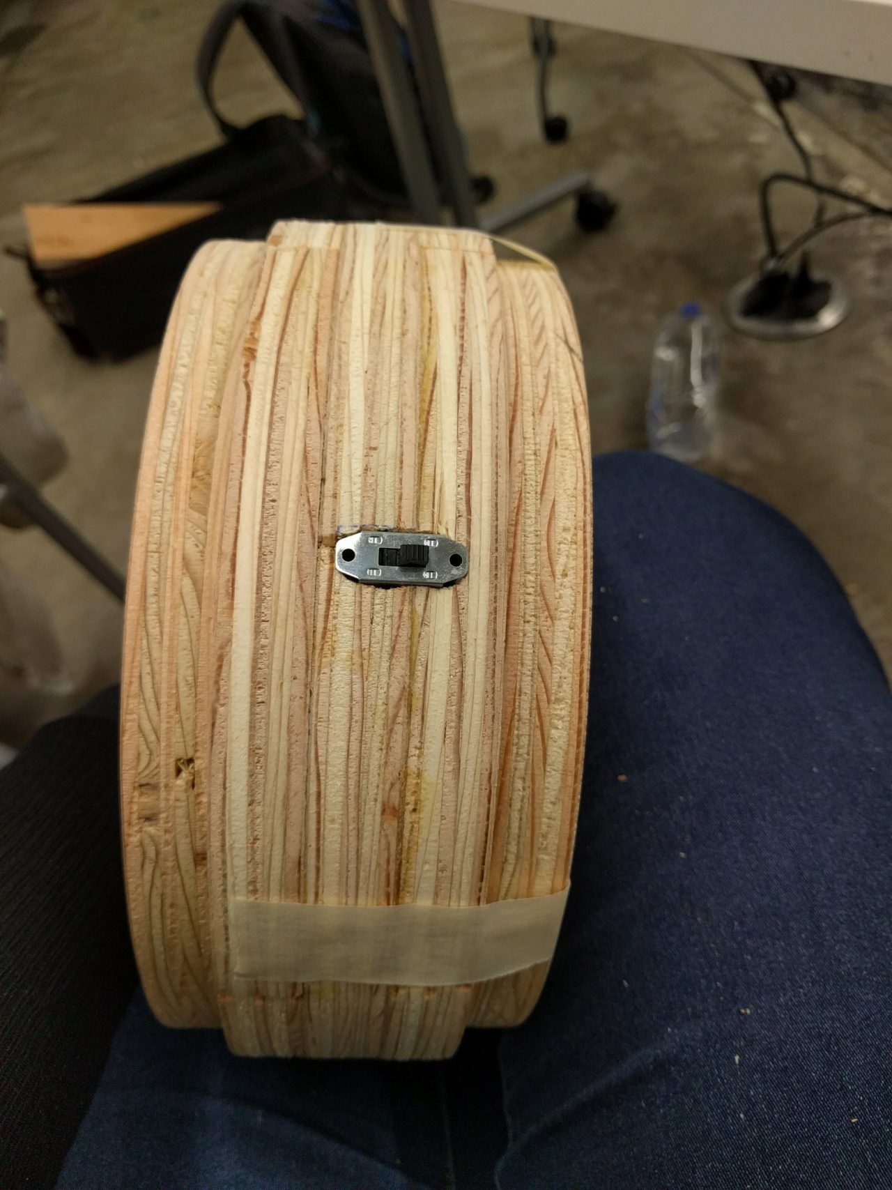
- what did you design? The actual path of the maze in Inkscape, and then the walls of the maze that would allow you to have that path. Also, how best to force the player to trigger the input sensor. The outer container.
- What materials and components were used? 2 sheets of .75in Furniture grade birch plywood, HS-322HD Servo motor, 1 R-LED, 1 visible light phototransistor, 1 ATtiny45, 1 ATtiny44, 1 20MHz resonator, 1 5V voltage regulator, 1 9V battery, various Resistors, Capacitors, header pins, and connecting wires.
- Where did they come from? Electronics from fablab inventory, servo motor Servo City (repurposed from a previous project, ~6yrs old!), birch plywood from Home Depot
- How much did they cost?
- Servo motor ~$11-$30
- Birch ply ~$20 for the amount I used (half a sheet)
- Resistors: ~$0.10 each
- Capacitors: ~$0.10 each
- ATtiny44: $1.18
- ATtiny45: $1.23
- Visible Light Phototransistor: $0.15
- Red LED: $0.13
- Single sided circuit stock: $1.40 sheet
- Resonator: $0.43
- Voltage regulator: $0.32
- 4 pin posiion header: $0.66 each
- 6 pin position header: $0.60 each
- 10 color ribbon cable: $38.07 for 50'
- What parts and systems were made? Entire wood housing, milled and glued together with wood glue. Electronic components for input and output (not the servo).
- What processes were used? computer-aided design (Inscape, Onshape, Vcarve), computer-controlled cutting (Milling PCM, Shopbot), electronics production, 3D scanning and printing (didn't make it into the final version, but used in prototyping), electronics design, computer-controlled machining (Shopbot 3D milling), embedded programming of output devices and input devices, networking and communications
- What questions were answered? Is it possible to have an adversarial maze that can detect when you pass a specific locatin? Yes, but it is impecfect.
- How was it evaluated? If the center turned to force the ball onto a different path, then that was considered a success. The sensor needed to be calibrated for a particular lighting condition, but all other cases after calibration were considered failure modes.
- What are the implications? At the very least, I am more confident in my ability to design and make things. The puzzl itself may not be very impressive, but I am impressed that coming into this class with no fabrication skills whatsoever that I was, with lots of help and guidance, make something that I designed. It's a very liberating feeling.
In conclusion, although it isn't perfect, and is still quite finnicky depending on the light levels, and I'm not sure that anyone would find this maze challenging or fun, I really enjoyed making it. In the future, I would maybe like to switch to an IR LED and sensor. The outer container could be a bit neater, and hopefully eventually I'll be able to send a continuous string of values and average them. But in keeping with the spiral design philosophy, it at least is a working prototype of what could be a very annoying adversarial maze.
Some relevant design files:
- Traces for phototransistor sensor
- Holes for phototransistor sensor
- Profile for phototransistor sensor
- Maze path designed in Inkscape
Here are additional pictures and videos:
Some demos:
Special thanks to Will O., Rob, Neil, Dixon, Julian, Nathan, Julia, Olga, Jordan, Lily, Richard and everyone else who offered their insight and commentary this semester! I seriously couldn't have done it without you all.