If the Shoe Fits
Then wear it. If not, then spend 20 minutes enlargening a slot in the wrong location.
I wasn't really sure what to make this week, because making something big seemed intimidating. In the end, I decided to try to make something that I would consider useful. Because our Shopbot has a maximum bed size of 4ft by 4ft, I designed my shoe rack such that all of the parts could be cut from one piece of 4ft by 4ft of OSB. Just in case I messed it up and needed to do another cut. This was the final design that I produced in OnShape. I made sure to add the T-bones so the pieces would fit together.
I also created some CAD designs to check what the optimal thickness was for my joints. I exported my CAD designs as a parametric DXF file and opened them up in Vcarve to make slight edits. With Rob's help I was able to turn my designs into valid shopbot files. Some important points that I noticed were that you needed to group vectors together because DXF files don't do that automatically. I could have done that in Inkscape, but the Vcarve ability is just as good. Also, when setting the depth, it was often a bit better to go slight over what was expected, just to make sure the cut goes all the way through. I created the different thicknesses by going from 90% to 105% of the reported thickness in 5% increments. In the end, I found that the 90% of the thickness actually worked the best. Here is the piece for cutting the thickness. This test cut also functioned to determine if I needed to adjust the depth of the cut in Vcarve.
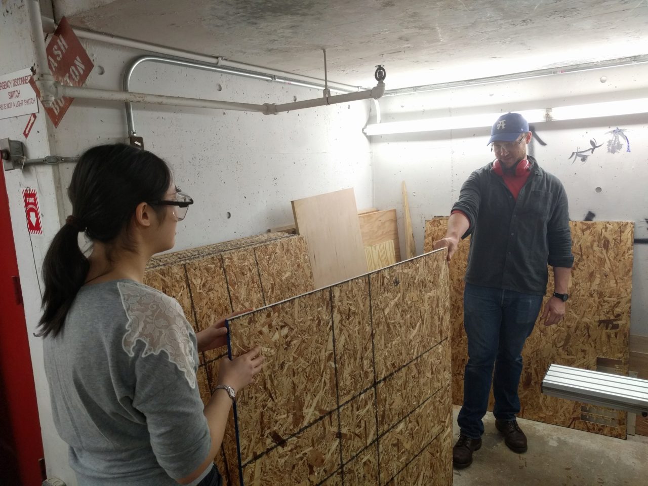
After making some adjustments to account for the best fit in the joint in OnShape that took way longer than it should have, I was ready to try to cut my design. After laying it out in Vcarve, Joe helped me to look over the layout becuase it was a bit tight and determine where would be safe locations for screws. He drew a diagram that we later transferred to the stock.
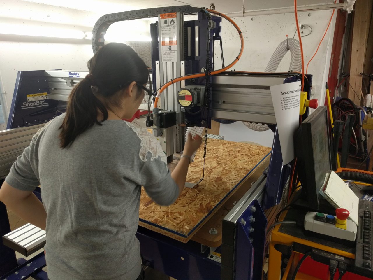
After checking the layout, we picked out our stock piece of OSB, making sure that it bowed up from the bed of the shopbot after we put it dowm. This was so that applying screws near the perimeter would help level out the stock. After aligning the corners, Joe helped me to transfer the diagram of safe locations for screws onto the board. I screwed down the board, making sure to stay within the boundary.
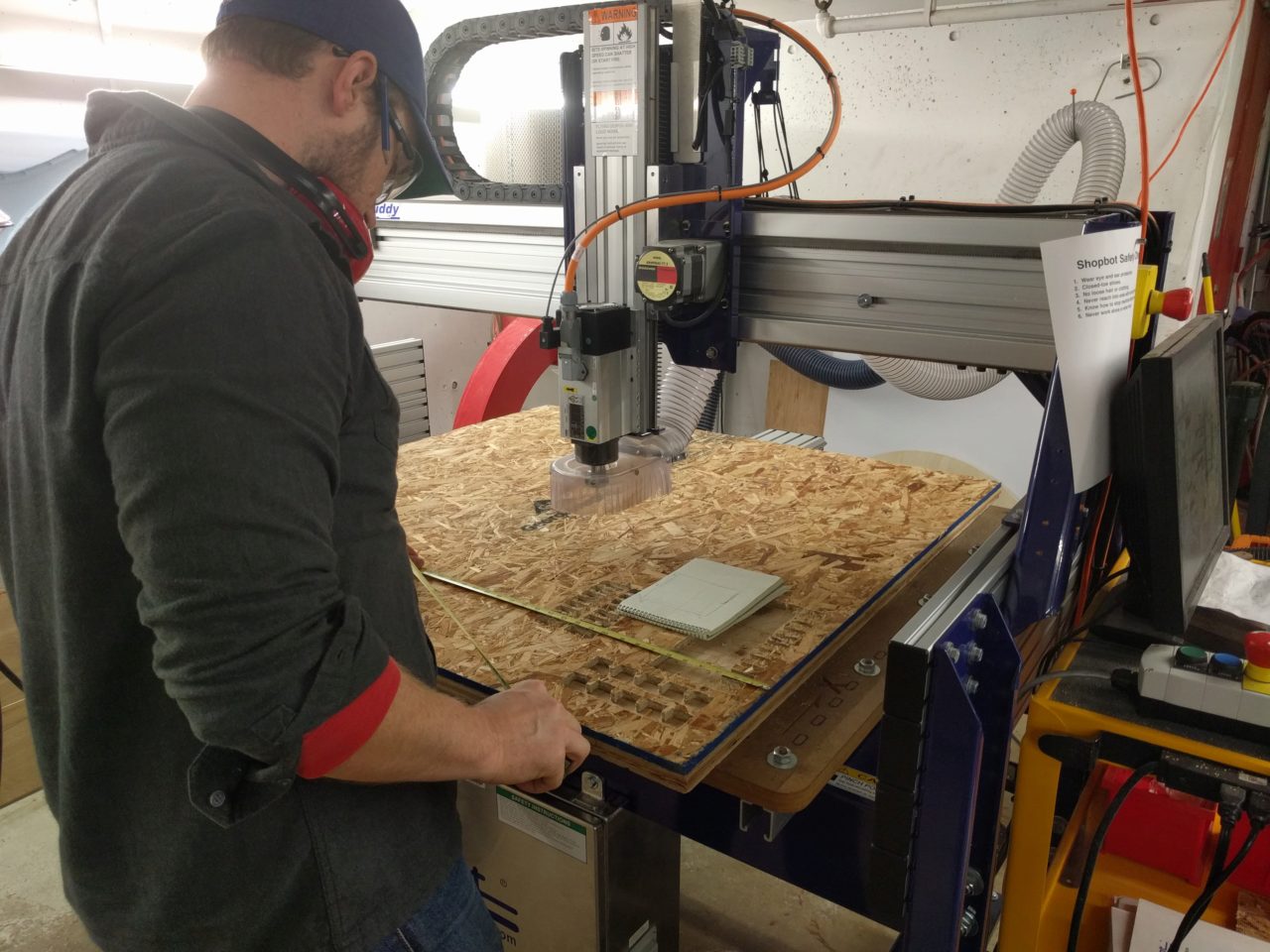
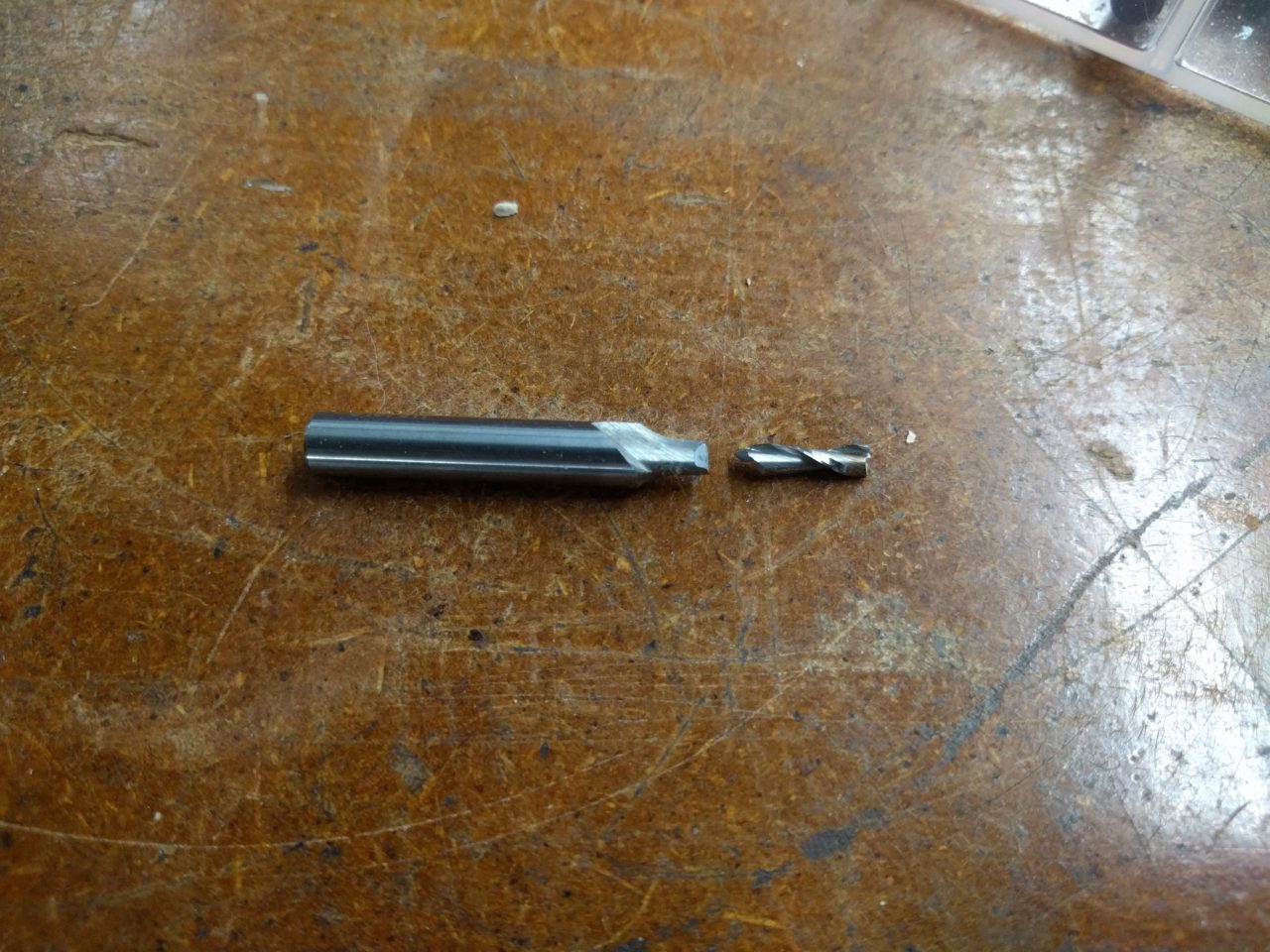
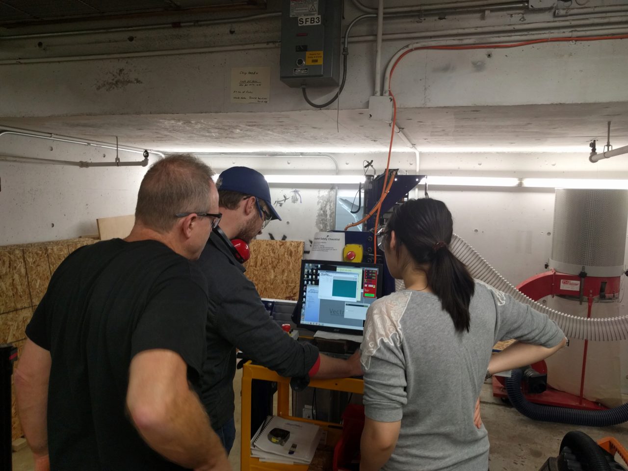
At this point, we needed to zero the machine to the proper origin. While we were zeroing the machine, the controls froze. Joe suggested that we restart the program on the computer, which did fix the problem, but appeared to confuse the machine, because when attempting to go to 0.5 in the z-axis, the bit actually plunged into the board and broke! We went through the appropriate replacement process that Rob taught us in the safety training and brought the machine back to proper functionality.
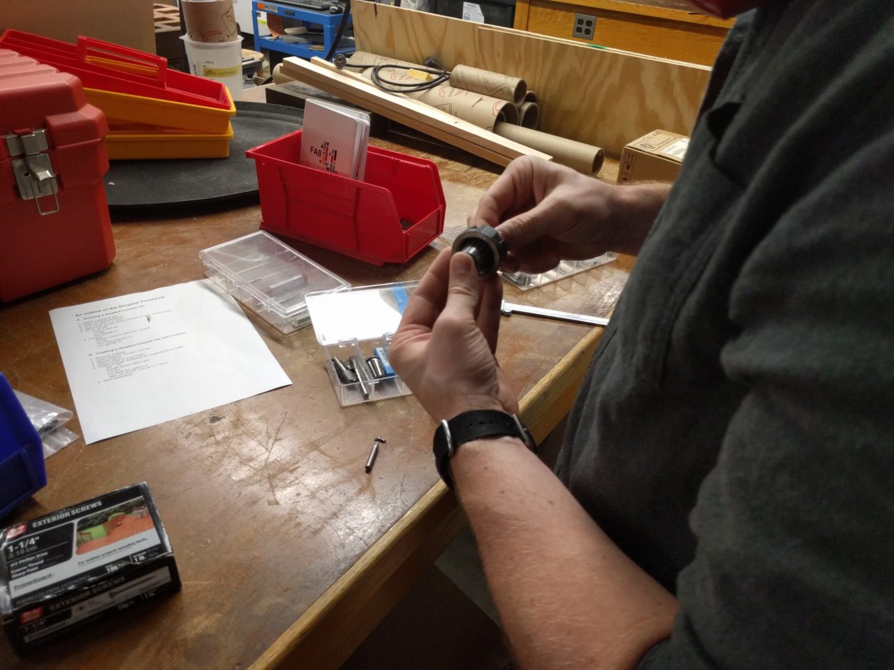
After replacing the bit, we re-zeroed the axis using the automatic Z zeroing with plate feature and adjusted values like jog speed and turn speed per Daniel's expertise. We then performed an air cut with the milling head 3in above the surface of the stock. We double checked to make sure that the milling head would not collide with any of the screws used to hold down the stock. Although we were pretty sure that the milling head would not have hit them, we took out two screws just to be safe.
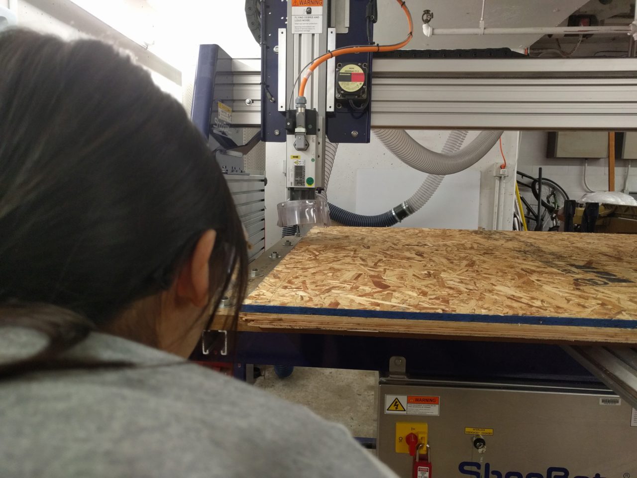
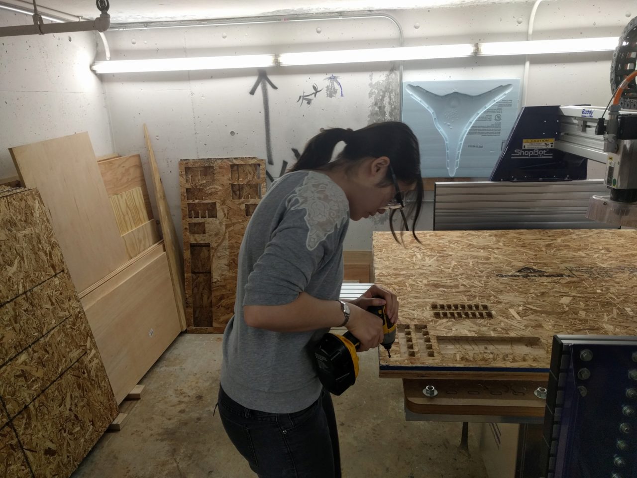
After that, we ran the same file again, this time cutting into the stock. An important thing to keep in mind here is to make sure that the spindle is rotating at full speed before attempting to cut, or else we risk breaking the bit. I stayed nearby, ready to hit the emergency stop if anything went wrong, but the machine basically just did its thing for the next ~20 minutes and produced the final cuts without problem. Here's a close up of the finished cuts.
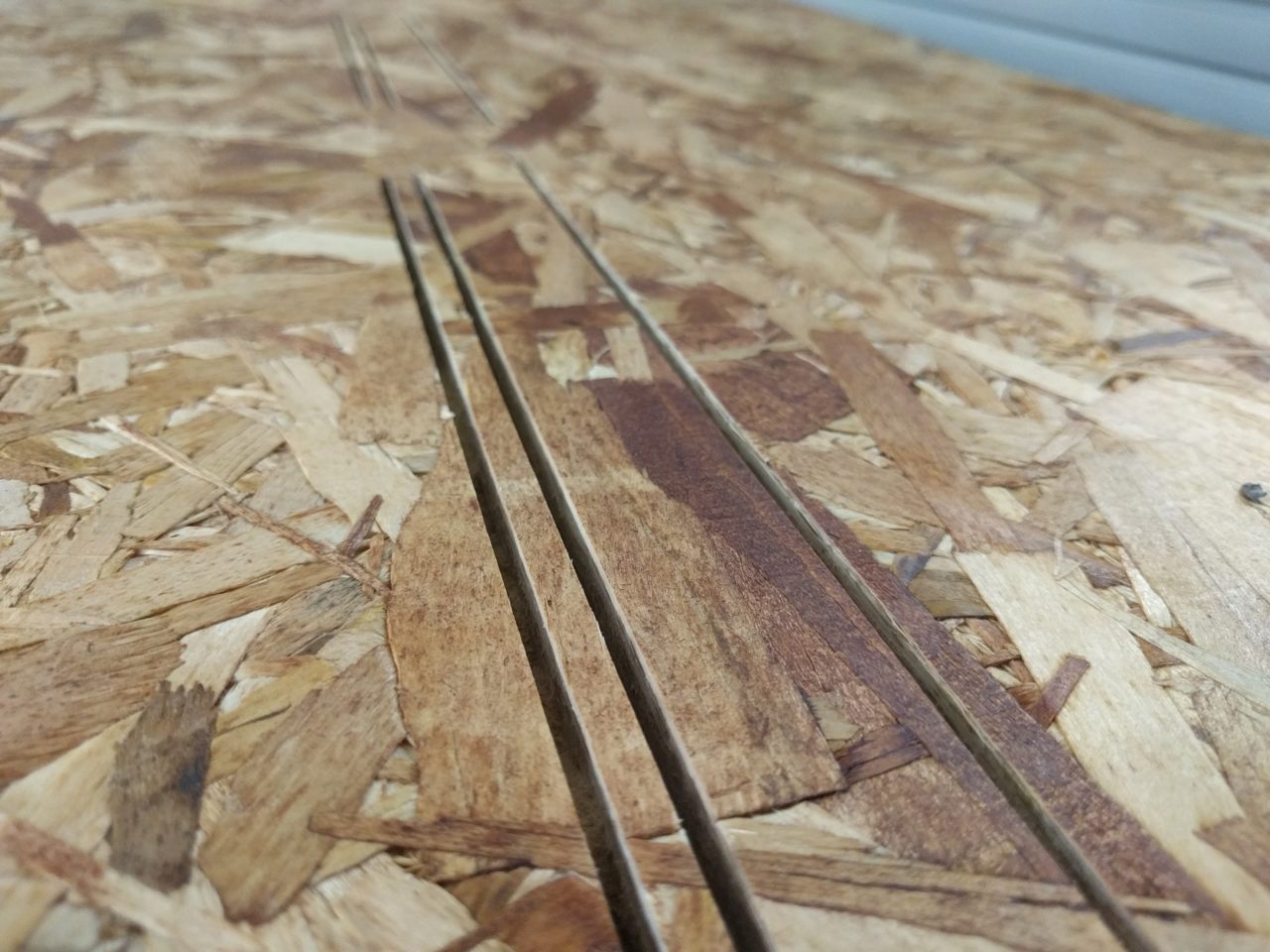
In hindsight, I actually wished I had used fewer tabs. The pieces were big enough that they would probably have stayed in place without them. Having the extra tabs meant a substantially longer clean up, and in the end, the uneven edges introduced some problems in my joints that had to be fixed with a file. Joe and Daniel also recommended to me that in future designs, I should use chamfers or things like that to help ensure a smooth join. I recognize that this would have been hard to do for this week's assignment, but I will keep it in mind for future designs.
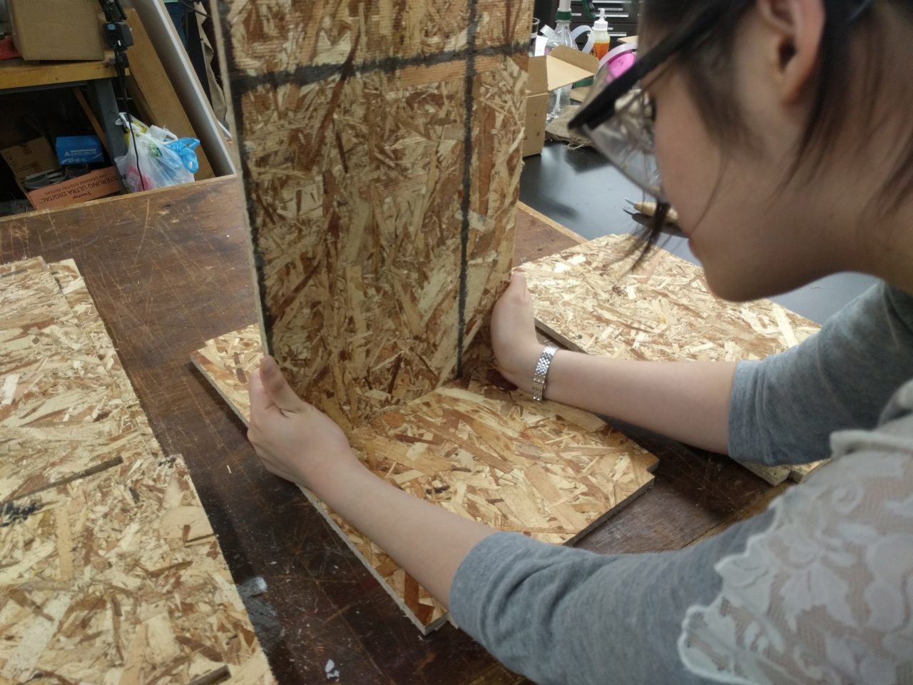
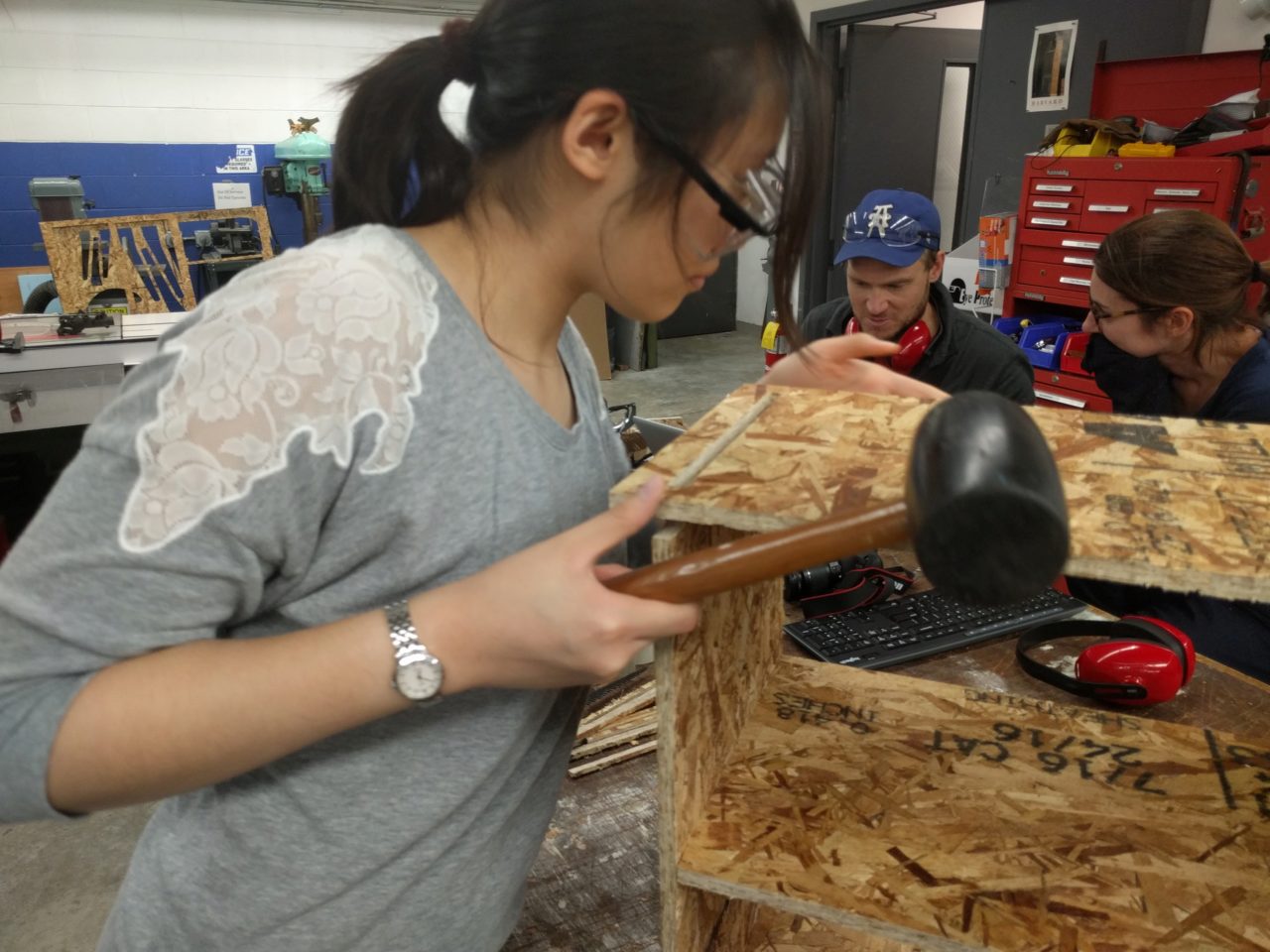
After cleaning up the tabs and removing most of the sawdust, Will O. helped me to assemble the shoe rack. Most of the joints went on pretty smoothly with just the extra pair of hands and a rubber mallet, but one joint, just would not fit properly.
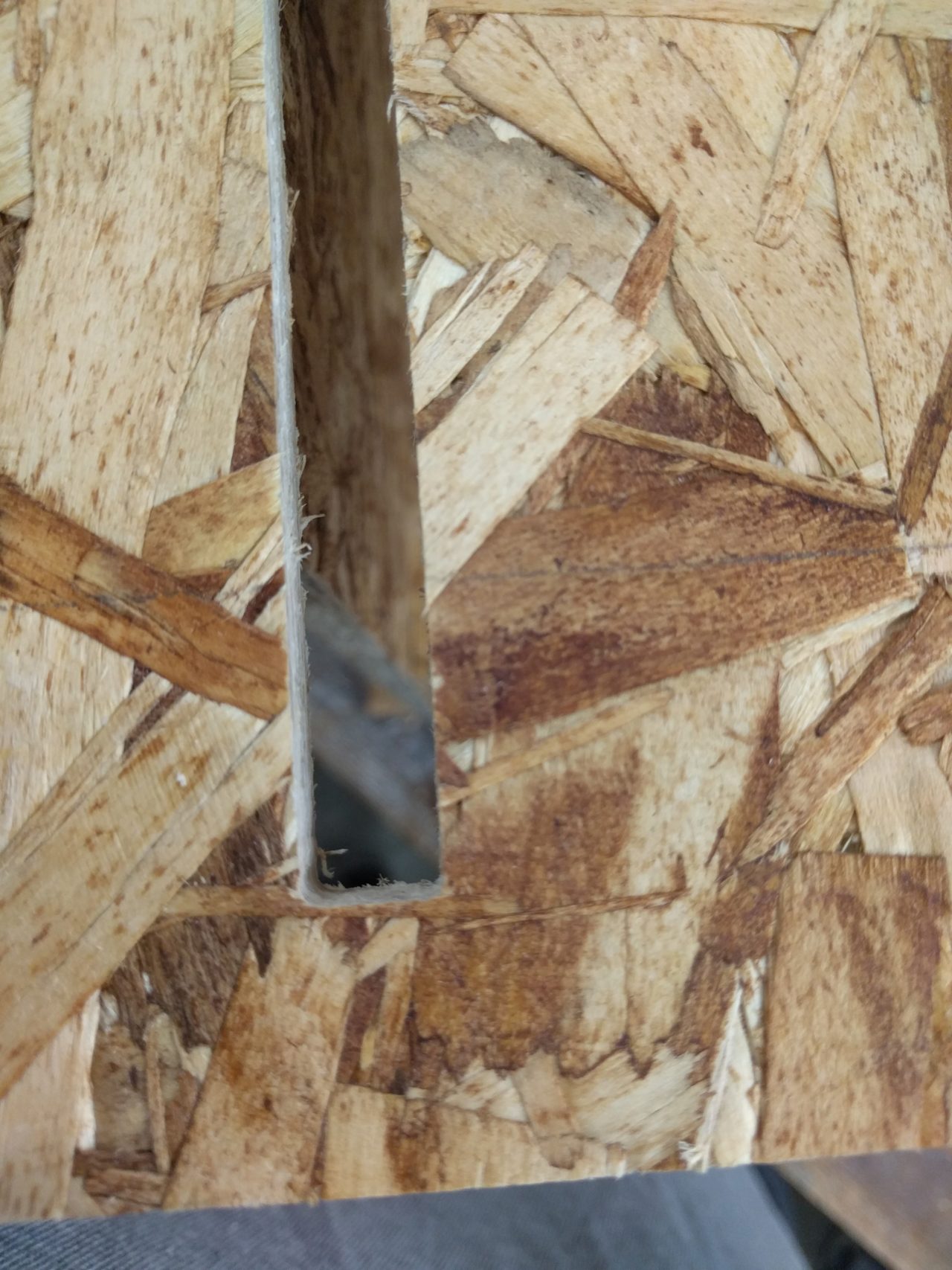
The joint in the following picture caused a lot of problems. First, the piece was bowed slightly out due to the natural bend of the OSB, but the piece I was trying to join it with had a significant bump in the center that would not allow the slot to slide over the tab. Because it was bowed out, I couldn't tell where the actual pain point was and enlargened the slot on one side before realizing the true problem. As a result, this particular joint has a small gap between the slot and the tab. However, the rest of the tabs were tight enough that the piece still held in place.
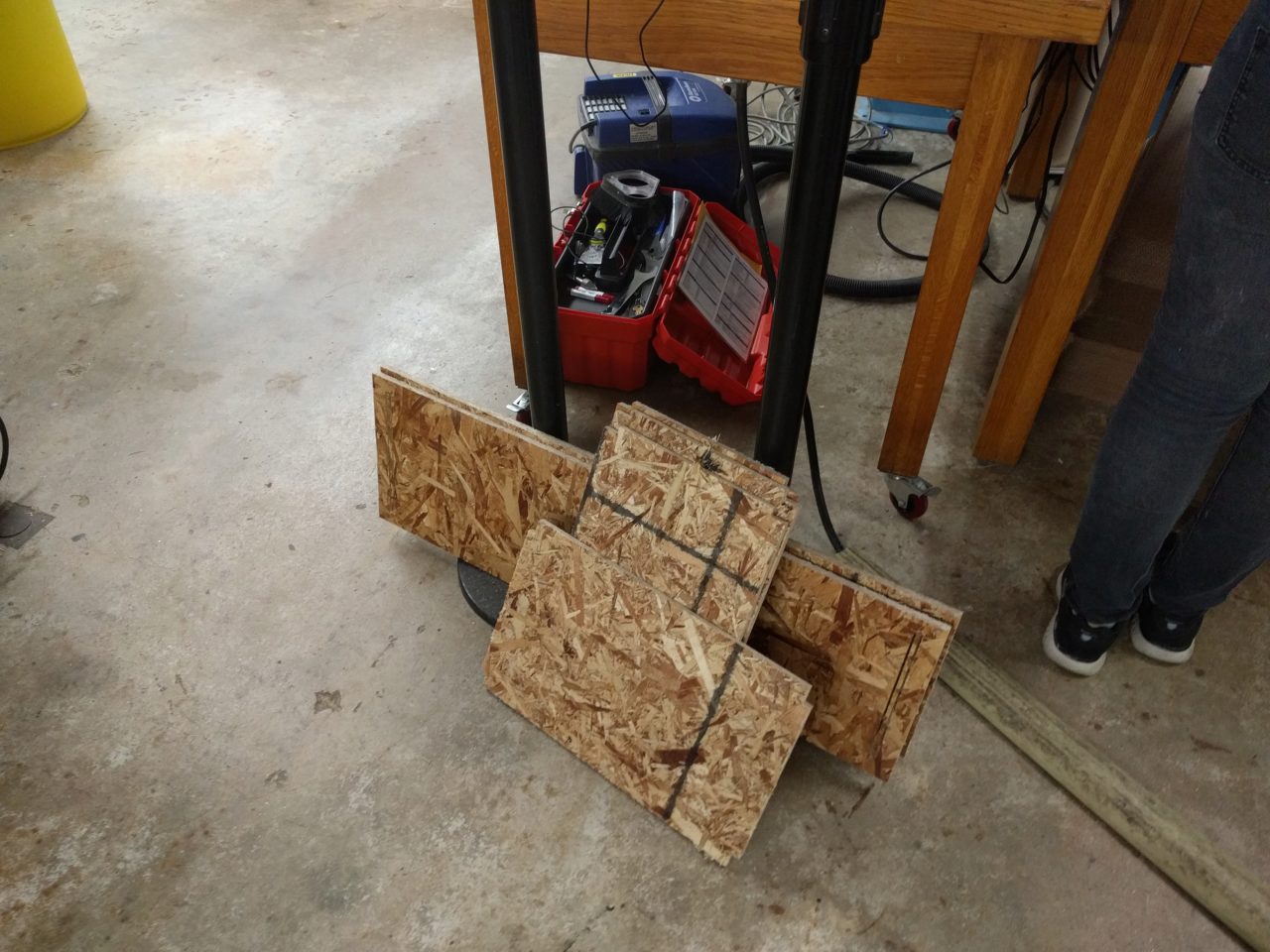
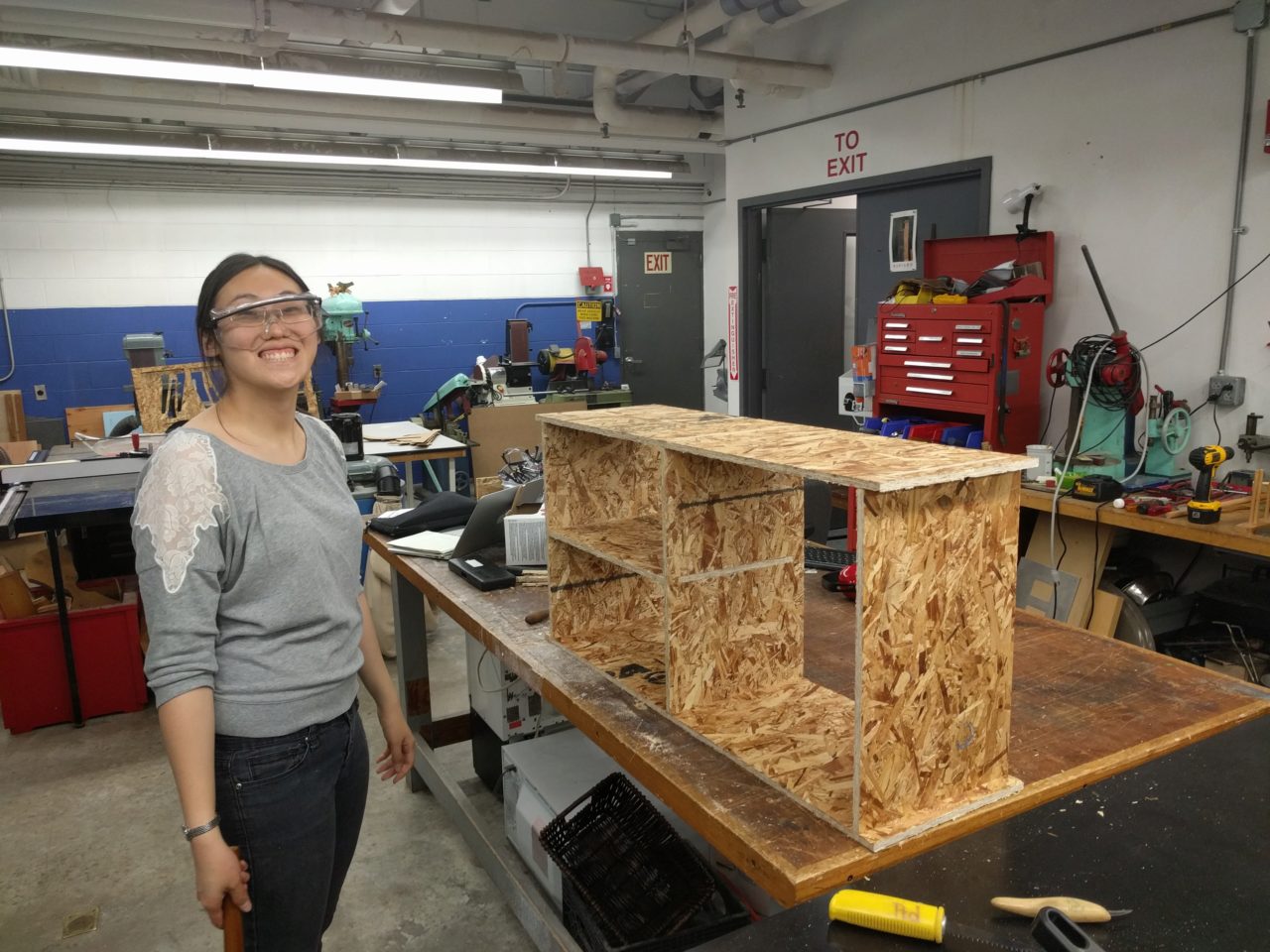
Here is the shoe rack, just after assembly.
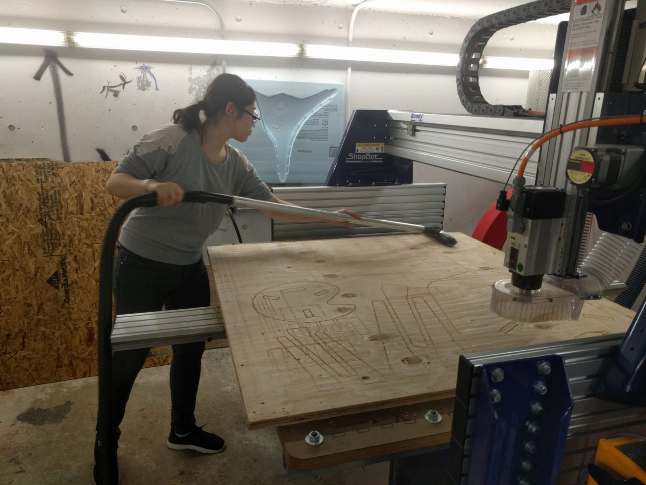
I then vacuumed up the sawdust on and around the machine as well as on the surface we were working on. Finally, it came time to transport it home, and thankfully, I was able to carry it on my own. For all of the cons of using OSB, at least it's pretty light...
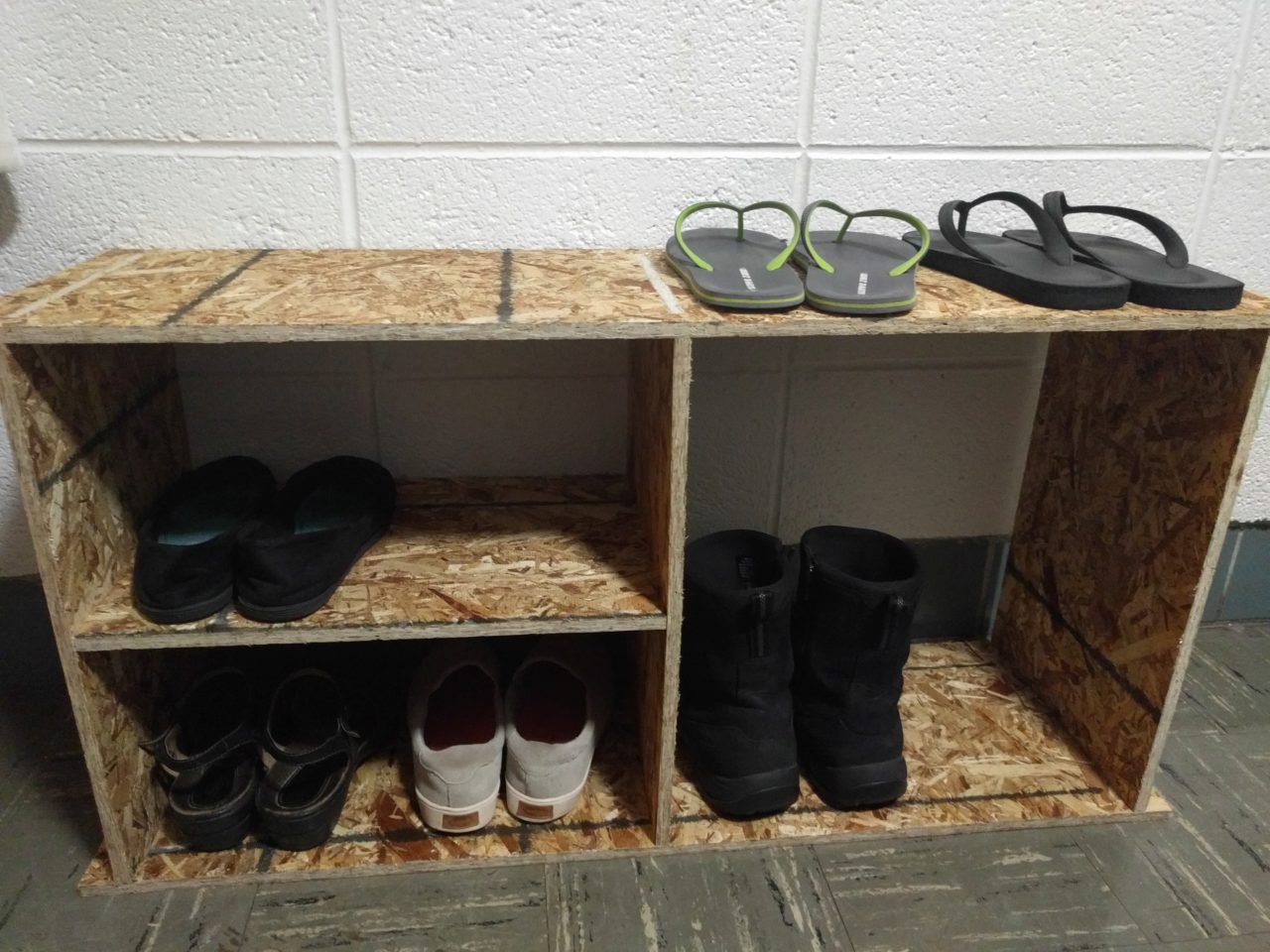
Here is the final product, serving its intended purpose.
Special thanks to Joe, Daniel, and Rob for their help and insight! Also thanks to Will O. for helping me document the process.