n e t w o r k i n g
This was an exciting week because it was the last component I felt like I needed in my final project board. So in addition to implementing processor to processor comumication, I started combining all the components (servo, step response button, and communication) into a board.
Because I am planning on making some wearable pieces of jewelry for my final, I also put some time in streamlining the servo and power connections. For the final board I plan on removing the ISP headers after programming and replacing two pads with a step response input.
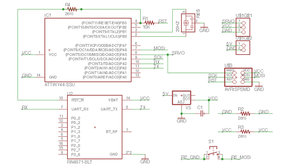
Here is the Eagle schematic. I'm using 0 resistors to bridge traces when there are tricky connections
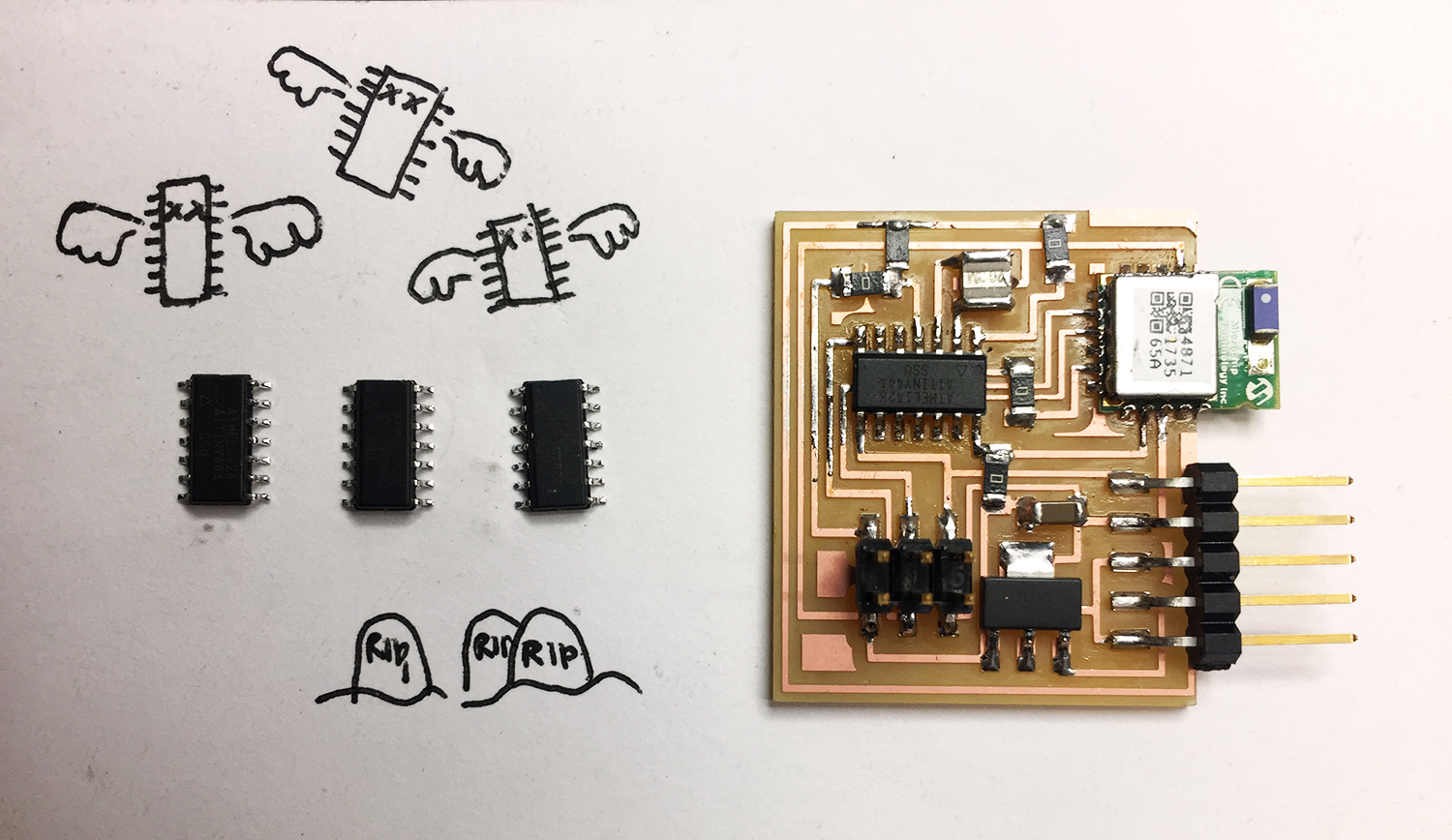
Milling went smoothly, but that was the last thing that did...I misconnected one trace, but luckily I was able to cut it with and blade and make the correct connection with another zero resistor. I was finally able to establish a connection and program the board. Here I ran into a problem I have never encountered before. I was able to program and set the fuses but when I tried again, it threw a connection error and the board was no longer recognizable. This make me think my program was breaking the ATTiny 44. So I replaced the 44 and uploaded the servo sample code to be safe. The same thing happened again!
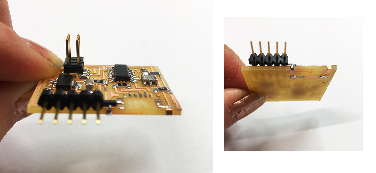
I removed the ATTiny 44 and the bluetooth module. Here I noticed leads on the underside of the bluetooth module. My traces had left a patch of copper that must have shorted the board and burned the 44 when I ran the program the first time.
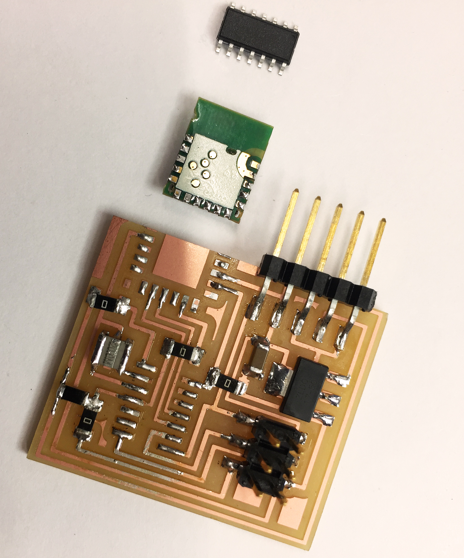
A close up of the ATTiny 44 killer.
I also noticed I had the wrong voltage going into the bluetooth module. So I added a 3.3V regulator to the power coming into the module. I used some scrap copper from the vynl cutter to wrap a connection around the back.
After all of this I finally got the servo up and running like I had hoped. Next I loaded a program to use the ISP header as an connection to some step resistance pads. My goal was to have two boards use capacitance to sense when they are with proximity to each other. At this point I started wondering if I could also use capacitance to "communicate". Then the bluetooth module would be unessicary and I could streamline the board even more. Here is my sketch of how I think this could work.
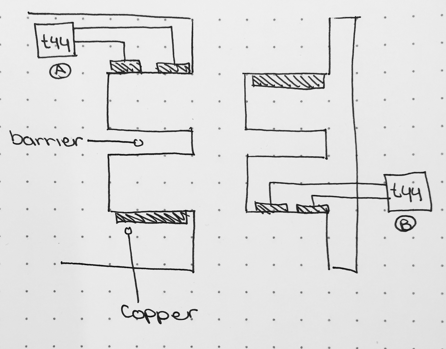
If two objects are shaped so that only they can align with each other, the form of the oject would act as the "ID", and the change in capacitence would act as the "signal". The test below is using a servo on one board to send it's "state" to another transmit-recieve step response board. The step response board is sending serial to the computer and a quick python script is displaying the state of the servo. The servo has a seperate power supply and is not connected to the board nor the computer.
This was proof of concept enough for me that this could work so I took off the bluetooth module since it was now redundent. The send board is on the left and the receive board is on the right.
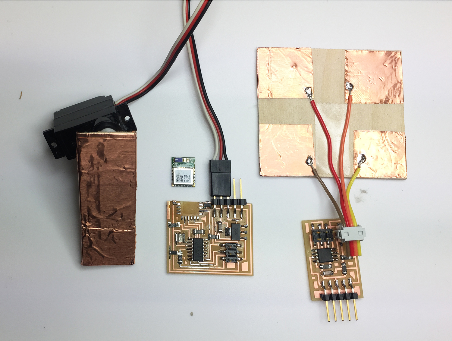
I think they need to be integrated into shapes that act as an analog ID so it only reads messages sent by the servo on another identical board.