Final project: 808s and Heartbreak
Hi! This is a set of stream-of-conciousness documentation I’ve done as I worked through (and continue after the class to work through) designing and building a prototyped drum machine project as culmination of the class. I’ve built a basic drum machine - it records beats and it plays back recorded beats - a simple automaton. It combines a slew of skills from the class: on the electronics side (hardware, software), ATtiny45s read and write signals along a serial bus to a raspberry pi, which on the one hand manages the machine’s logic (states, synchronization) and on the other hand does all the audio (codec, amplification through a breakout board). The best source to understand this is the source code. On the non-electronics side, I built sensors (molding and casting), housing for the sensors (3D printing), as well as a form factor for the whole thing (laser cutting). There is a ton that can be iterated on and improved, as well as things that could or should be done differently. Still, for a minimum viable product, I simply have to swap out the sensors to add responsiveness and robustness when I’m whacking at this with a drum stick. This was an awesome first deep dive in digital fab!
Bill of materials (BOM):
- We were asked to keep tabs on what we were using. I’d decided early on to employ a raspberry pi to deal with audio. Anything I used that wasn’t from the fab inventory was from this design decision. It was not a cheap choice…
- Raspberry Pi 3 - Model B - ARMv8 with 1G RAM - 35.00
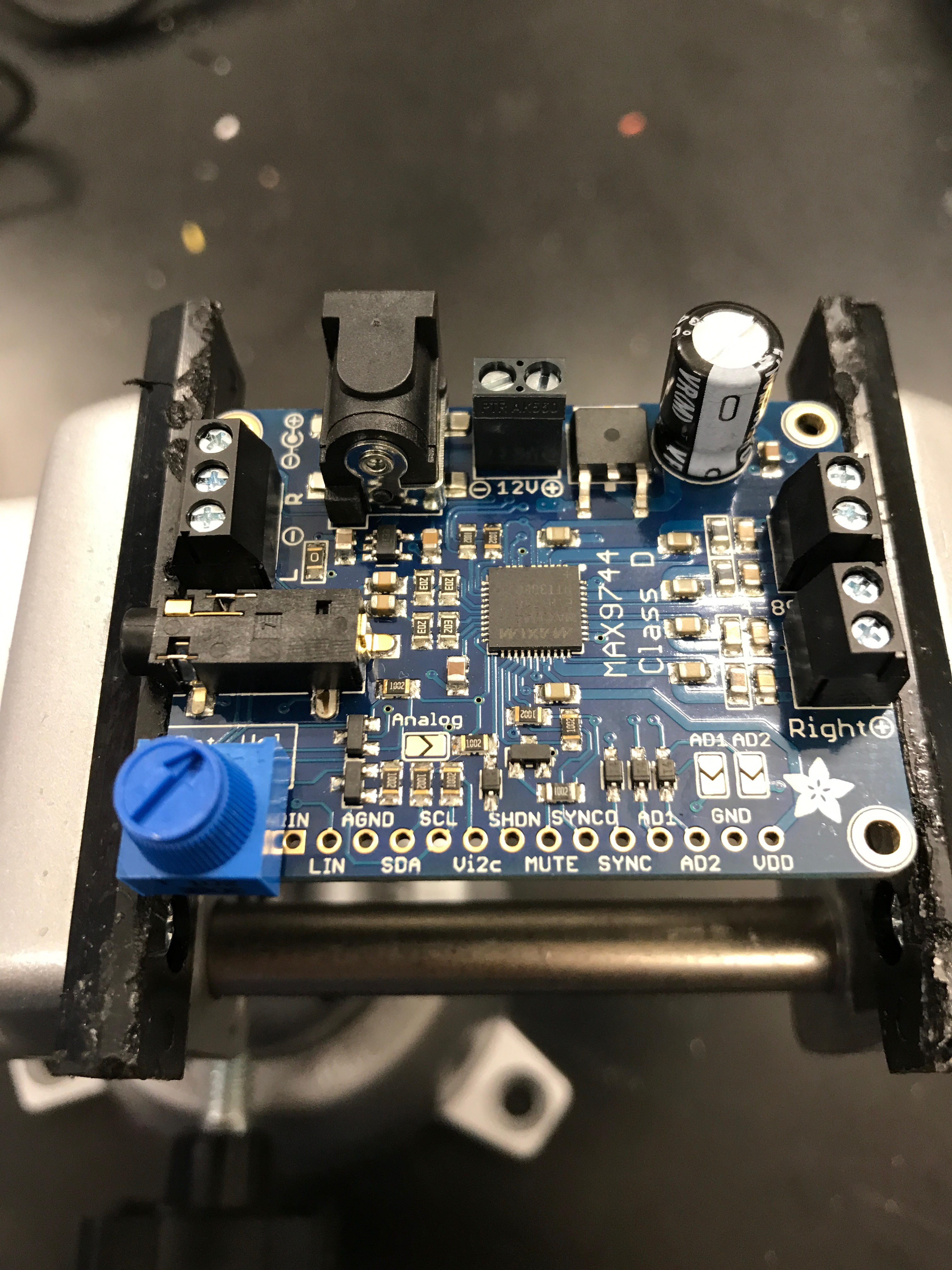
- Stereo 20W Class D Audio Amplifier - MAX9744 - 19.95
- 20W 4 Ohm Full Range Speaker - XS-GTF1027 - 14.95 x 2
Quick reference
- software and CAD/CAM repository
- boards: board = step response board + serial bus (asynch serial bus) board
- datasheets / documentation: ATTiny25/45/85, Raspberry Pi
Concept:
I’m interested in combining digital fab and drumming. When I started out, I spent some time researching lasers and laser sensing. I was thinking of trying to project a drum pad onto a surface that could be customized to have a few different kits, i.e.
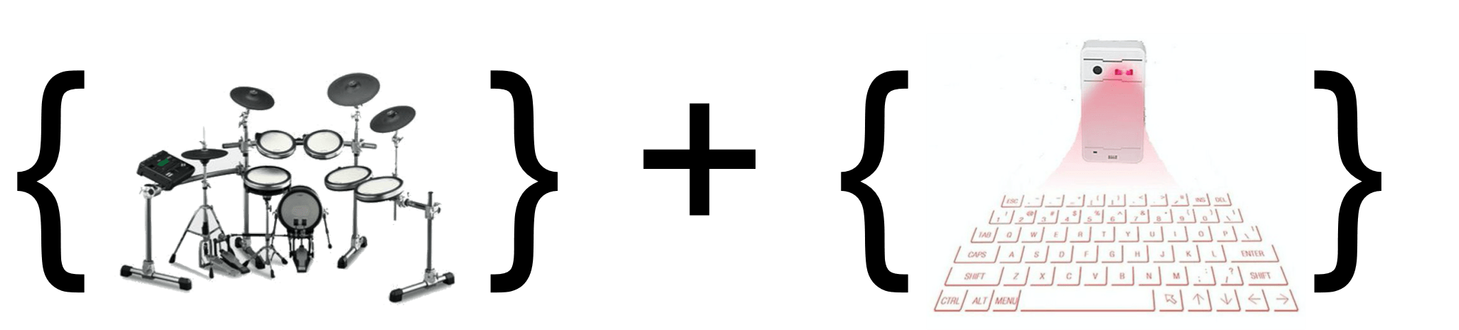
A few of the teaching fellows (and Neil) suggested I start with simpler input devices, and so I’ve switched focus slightly and have some sense of the form factor I want to continue with. I started out thinking towards bucket drumming, an urban art form requiring only a few five-gallon buckets :) I wanted to build a drum kit i.e. an electronic drum kit from a few 5 gallon buckets and have them each hold recorded drum sounds. Some time after, I switched again into replicating something like a roland 808, building that something would record beats and play back recorded beats to the user.
Roadmap:
After a sit-down with Brian, I’ve worked out a simple strategy for design.
- buckets have an input board, which takes input from a sensor / force sensor and sends output of 1. which bucket 2. how hard bucket was struck
- the signals are all sent to the main / master board or to an intermediary input board that routes the signal on if I’m worried about port / pin capacity
- this board is responsible for sending a signal to output. So a few things have to happen here. I have to read from an SD card, the signal has to be transformed by a MP3 coder/decoder, amplified, and sent to speaker
Electronics:
- Inputs
- On the input side of things, I’ll test out piezo sensing (this relies on charge that accumulates in solids like crystals and ceramics as a result of applied stress) - seems like this is the approach in electronic drums especially - and step response sensing (see Neil’s).
- What else? “nice to have” but not “need to have”… add a button or buttons to shuffle the MP3s being triggered by each bucket
- Outputs:
- On the output side of things, I’ll try to start simply and improve iteratively:
- without MP3 aka beep-boop board: adapt hello, world speaker to output a sound of a specified frequency
- with MP3:
- On the output side of things, I’ll try to start simply and improve iteratively:
Form factor
- pad / drum pad to sit on top of or set on top of bucket (from Molding and Casting week)
- housing for boards (from 3D printing week)
- housing in bucket
–
Documentation
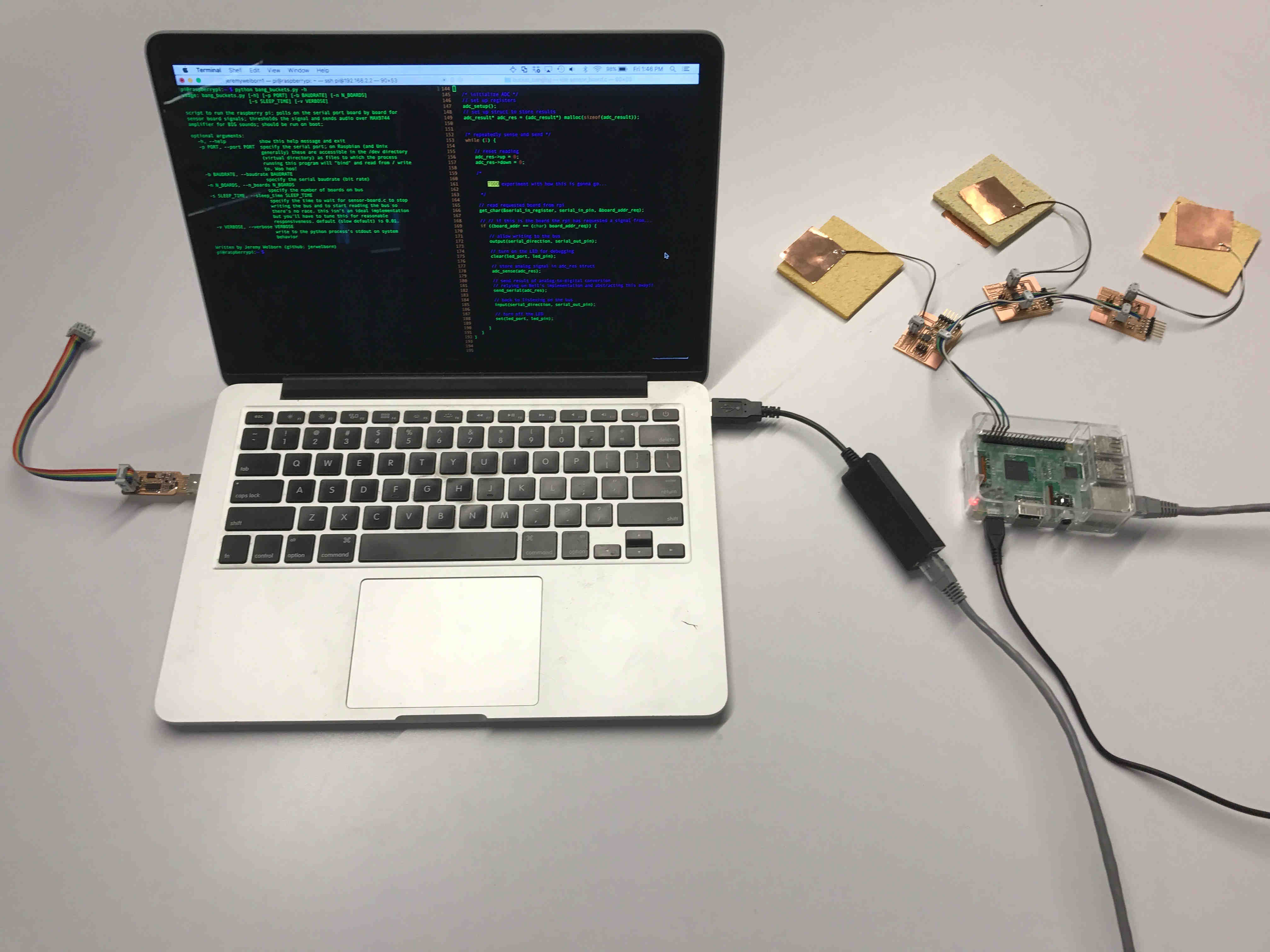
- I’ve started with electronics. To stay simple, I want to have sensor boards along a bus. A raspberry pi is the signal recipient. In simplest case for code, sensor boards take turns one and only one at a time on the bus and send readings to the raspberry pi, which does a threshold test and spits out a drum sound.
- inputs
- talked to Jim about async RS-like bus vs. sync I2C bus or SPI bus, asynch seems like what I want to do but I haven’t written the code to see whether this works
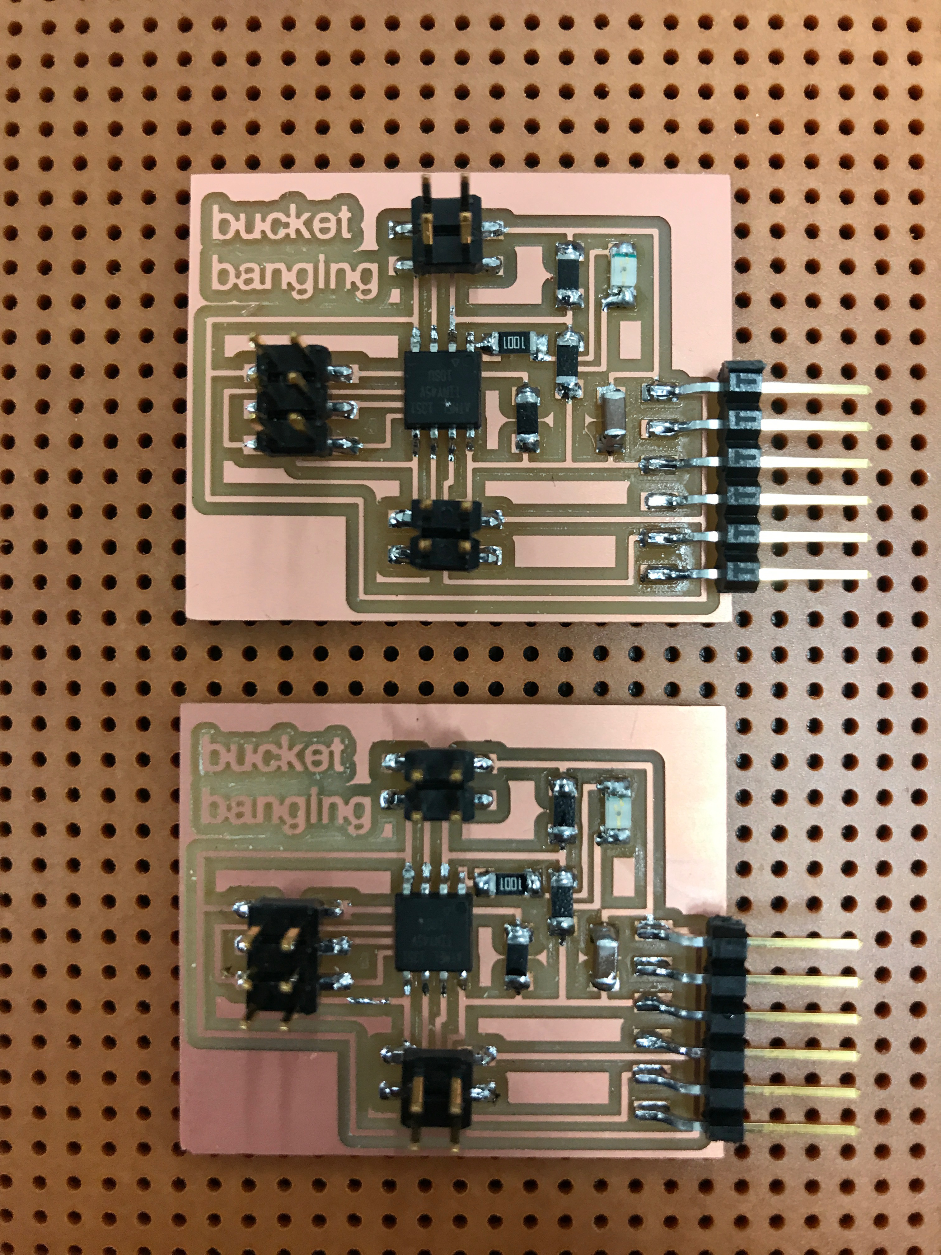
- building sensor boards to work with step-response sensing + piezo sensing
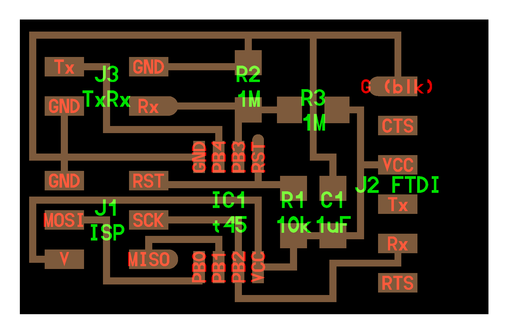
- basically what I want is serial bus board + step response sensor board with some adjustments
- what’s happening here?
- attention to power (power supply) by situation
- connecting several boards to the raspberry pi (i.e. when it’s working) - thought rpi had a 3.3V restriction but that’s not what it looks like on the pinout in particular
- connecting single board to my mac (i.e. when it’s not working) - doing this through ftdi so I can see the sensor in something like
term.py
- 2x2 header for bus
- reusing
PB0for tx,PB1for rx
- reusing
- 2x2 header for sensor - should work with step response, should also work with piezo
- using
PB3, PB4for tx, rx
- using
- oh should’ve use 2x3 as 2x2 bus
- attention to power (power supply) by situation
- outputs
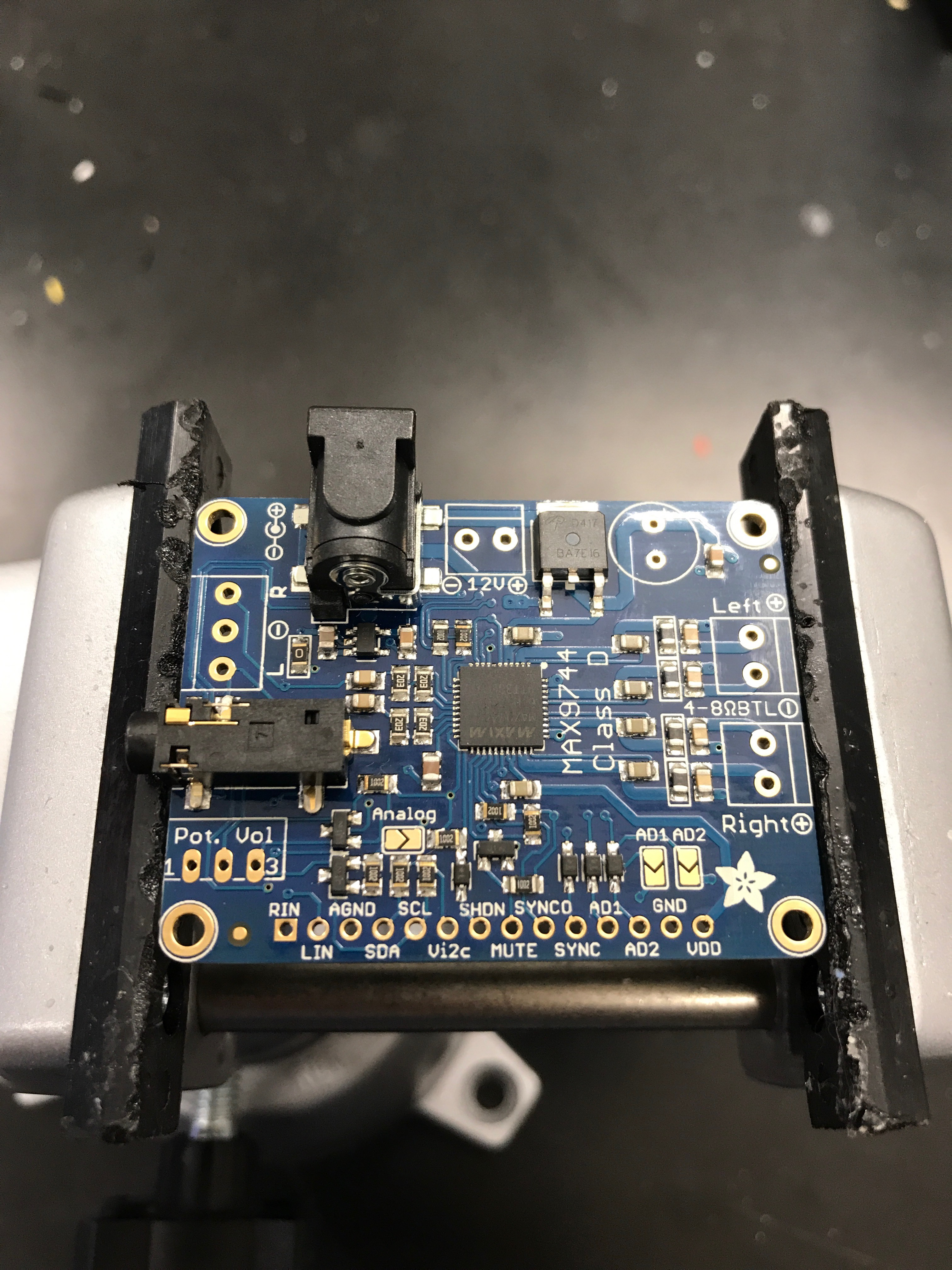
- didn’t want to deal with codec for MP3 (or coding / decoding whatever file format), also didn’t want to deal with building an audio amplifier… so went with Raspberry Pi + MAX9744 breakout board
- Raspberry Pi comments
- 1st time working with Pis so I’ve taken a ton of notes but will spare the reader rn
- MAX9744 comments
- board available at https://www.adafruit.com/product/1752
- board docs available at https://learn.adafruit.com/adafruit-20w-stereo-audio-amplifier-class-d-max9744/downloads
- RPi-MAX9744 IC2 available at https://github.com/adafruit/Adafruit_Python_MAX9744
- assembled MAX9744 amplifier (5-14V, trying to get biggest gain), tested with a few scrap speakers (P=V^2/R !!)
- splurged on https://www.adafruit.com/product/1732… see them soon!
- drove speakers from my mac’s sound card (through 3.5 mm jack) and from RPi’s sound card, RPi was super soft so dug deeper into RPi’s sound card
- … rabbit hole of linux audio hardware / hardware drivers
- http://www.instructables.com/id/Test-Sound-Card-and-Speakers-in-Raspberry-Pi/
- ALSA or Advanced Linux Sound Architecture is kernel API for sound card device driver
- ALSA utilities (
alsa-utils) e.g.alsamixerto interface with the sound card driver directly,alsamixeris is volume down / volume up from the terminal
- want RPi to be able to specify the volume given a signal?
- over I2C… should be simple
- or in software
- talking to the RPi over an asyn serial
- config with raspi-config
- bus w/ VCC on 4, GND on 6, Tx on 8, Rx on 10
- /dev/ttyS0 vs. /dev/AMA0` docs > config docs > UART or Universal Asynchronous Reciever-Transmitter (the chip for any async serial communication)
- not sure on 3.3V vs. 5V
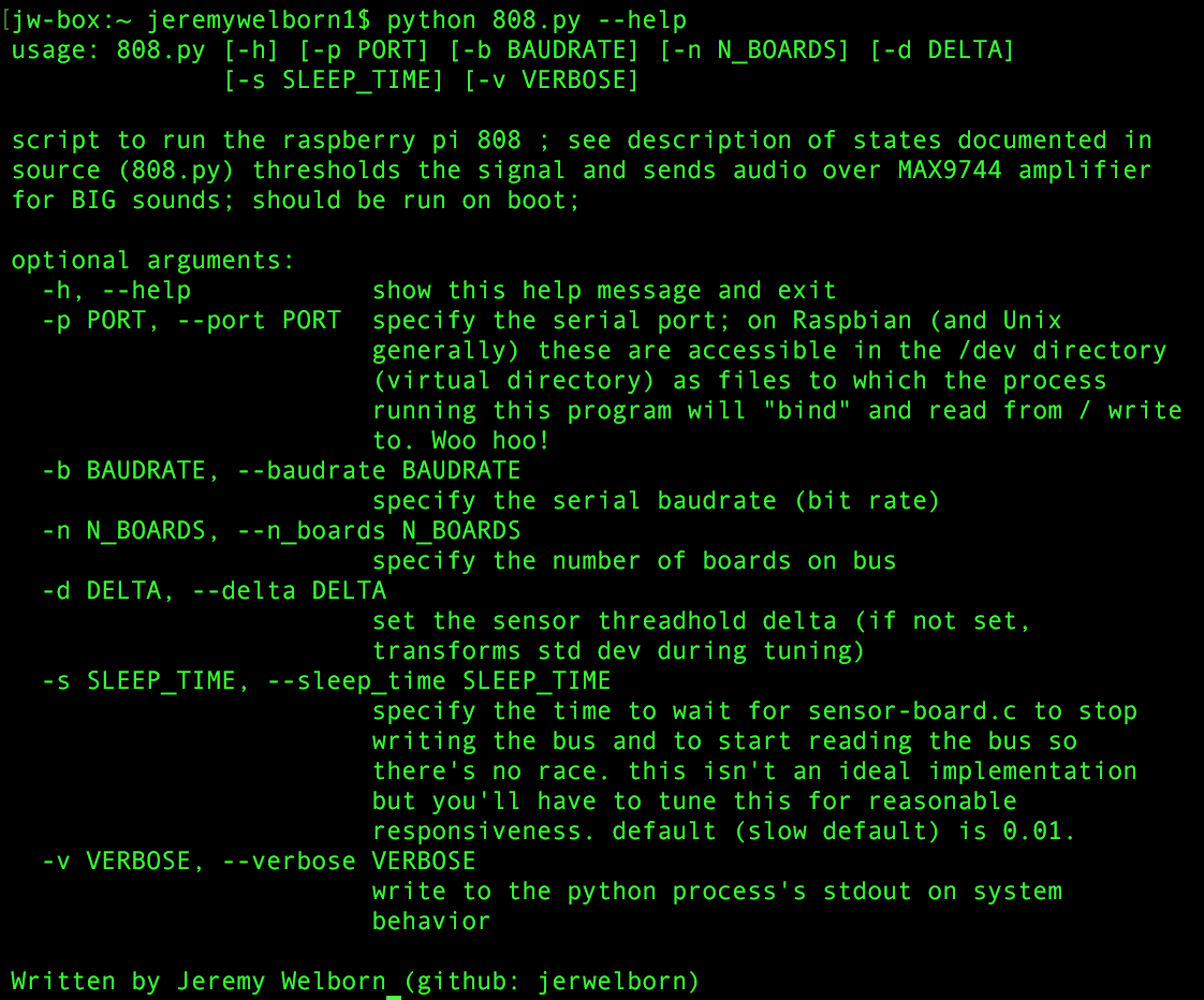
- see source code for docs!
Form factor
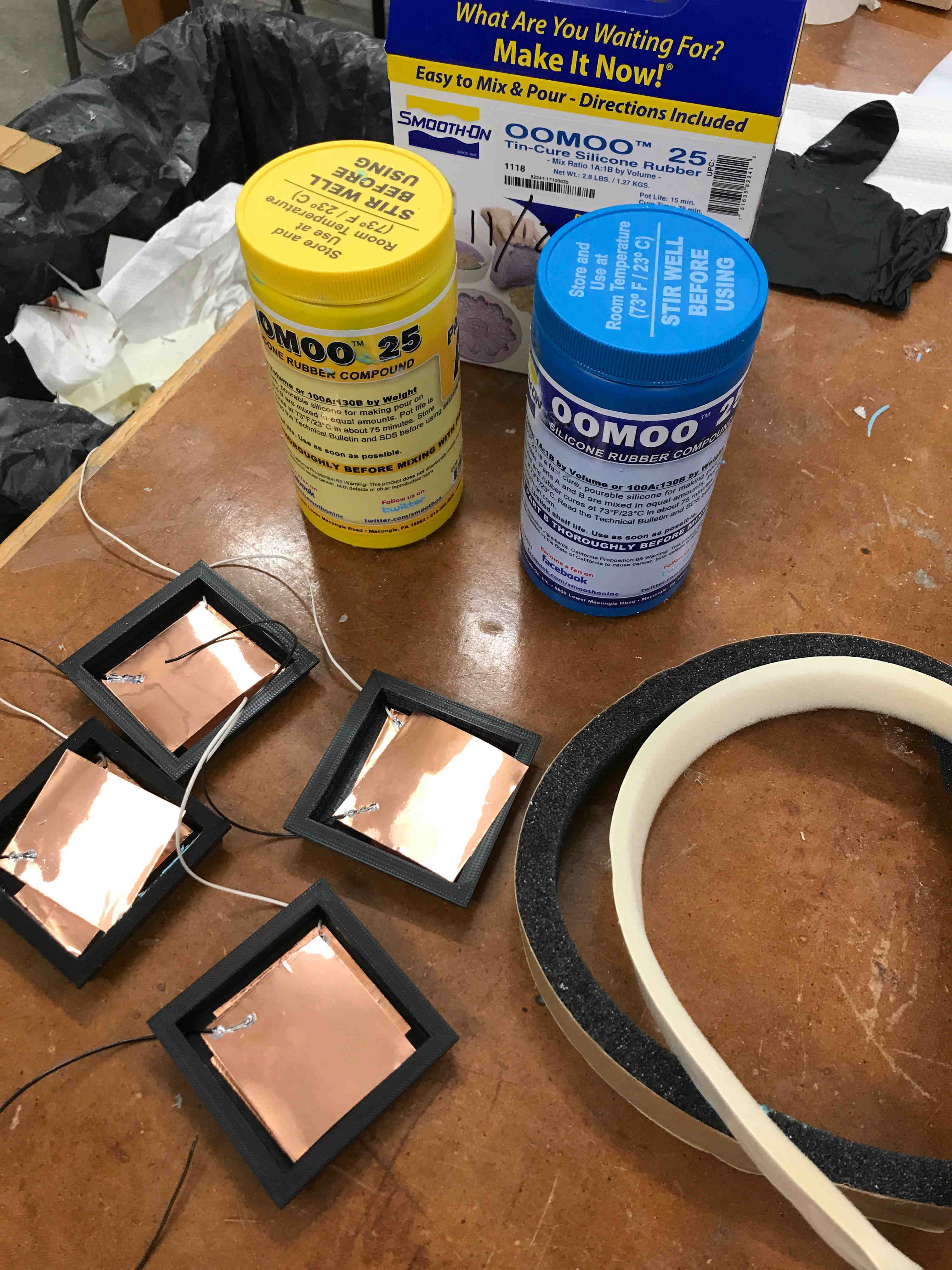
- sensors, housing for the sensors
- this was the trickiest area - building a reasonably responsive sensor
- I started with and stuck with the step-response sensor from class. The challenge I confronted was that, as is clear in the source code, the sensors are tuned to a “baseline” at the start, but after any disturbance or depression to the
txcopper pad andrxcopper pad, they would not return to their starting state. I tried a few fixes, among them embedding foam between the tx and the rx for its elasticity - This is an easily evident area to return to
- housing
- Check out Makercase. I built out a box-y build at SEAS’s Active Learning Labs.
In its final form:
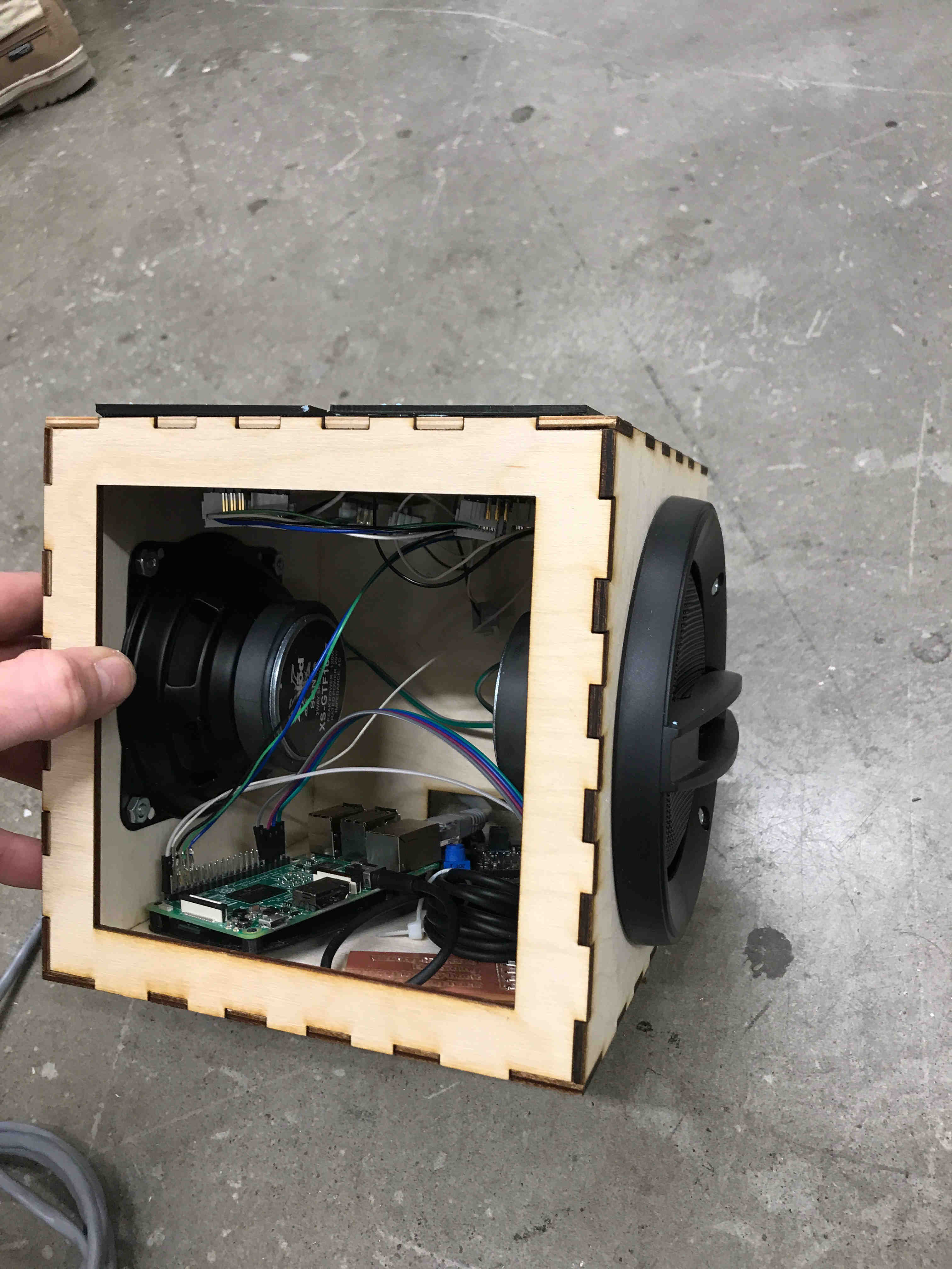
When I return to campus, I want to swap out the current sensors with something robuster.
A big thanks to Rob and Brian for help along the way.