Week 7: Embedded programming
This week we were exposed to embedding programming - writing the code that the AVR controllers run. Assuming some basic background in computing (if you have a simple mental model of how a processor, a processor’s registers, and I/O devices interact), the best way to get going is the ATtiny datasheet.
High-level on AVR programming
As a simple first step, especially for the hello, world style boards where the ATtiny44 is activating an LED via an output pin when a signal from a switch arrives via an input pin, I found that a working knowledge of the pins, ports, and registers got me going:
- the ATtiny44 controls other components on the board (roughly speaking, does I/O) by sending and receiving serial (0 / 0 V or 1 / 5 V) signals. These signals are received and sent by reading and writing to “pins,” which are arranged in “ports,” which have a small set of registers
- the registers for a port define how the pins for that port behave:
-
set pins as input pins or output pins via the
DDRxor Data Direction Register for port x, e.g.:/* * 1st 4 pins on port A are outputs (can write to them) * 2nd 4 pins on port A are inputs (can read from them) */ DDRA = 0x0F; -
write to output pins via the
PORTxor Data Register for port x, e.g.:/* write 1's to the output pins of port A) */ PORTA = OxFF; -
read from input pins via the
PINxor Port Input Pins for port
-
- A few other features we brought up are straightforward also. The ATtiny is single-threaded, and interrupts allow asynchronous hardware or software event handling (check out this site).
High-level on tooling for AVR programming
Per usual, Neil showed us a slew of different environments for embedded programming. I wanted to work in C without any Arduino abstractions to stay as low level as I could. CrossPack wraps up GNU GCC, C libraries for AVR (allowing us to access to ports and pins), and avrdude, a utility that writes compiled code to the AVR’s text segment. For host ftdi communication, I’ve started working in CoolTerm.
Getting going
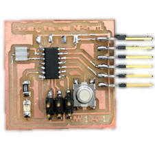
After digging through documentation, I wanted to see the hello, world board in action. When I put power through the programmer and the programmee (the board) though, my mac complained a USB device was drawing an unsafe amount of power. This suggested a short, and sure enough, some careless soldering had hooked up a high voltage and a ground trace:
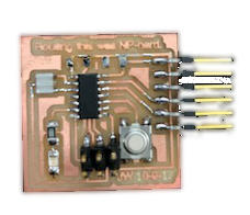
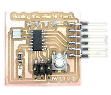
After resoldering, I had no trouble at all. Any of the code sourced from Rob’s tutorial was sufficient (with input pins, output pins adjusted appropriately. With the hardward hooked up correctly, I could readily compile and transfer the byte code through the programmer to the programee (using the avrdude utility).
It was instructive to see a few implementations, one implementation that reads and write registers and, another that abstracts away the bit banging but still requires thinking through registers, and another that abstracts away that too:
/*

    Code for ATtiny44 controlled circuit with button-controlled LED
    3 implementations, with marginally different uses of macros

    Button on PA5 (pin 8), LED on PB2 (pin 5)

 */


/**
 *
 * Version 1
 *
 */

#include <avr/io.h> // http://www.nongnu.org/avr-libc/user-manual/dir_74edb07caae428933d09e0931d8b44f5.html

int main(void) {
  // initialize
  PORTA = 0b00100000;                 // write 1 (high) to PA5, i.e. initialize pullup resistor on input pin s.t. when button is depressed, will read 0 (low)
  DDRB = 0b00000100;                  // set PB2 as output

  while (1) {
    if ((PINA & 0b00100000) == 0 )   // if PA5 is 0 (low) i.e. button is depressed
      PORTB = 0b00000100;            // write 1 (high) to PB2 i.e. turn on LED

    else
      PORTB = 0b00000000;
  }
 }

/**
 *
 * Version 2 - Charles Holbrow
 *
 *
 * Adds macros for modularity and maintability
 */

#include <avr/io.h>

#define bit_get(p,m) ((p) & (m))      // read bit m (check if bit m is 1) from register p (where p must be input register PINx)
#define bit_set(p,m) ((p) |= (m))     // write 1 to bit m in register p (where p must be output register PORTx)
#define bit_clear(p,m) ((p) &= ~(m))  // set bits to 0 in register p
#define BIT(x) (0x01 << (x))          // get 8-bit representation for register with 1 at bit x

int main() {

  bit_set(PORTA,BIT(5));
  bit_set(DDRB,BIT(2));

  while (1) {
    if (bit_get(PINA,BIT(5)))
      bit_clear(PORTB,BIT(2));
    else
      bit_set(PORTB,BIT(2));
  }
}


/**
 *
 * Version 3 - Neil Gershenfeld / Rob Hart
 *
 * Same as above, these are the macros Neil tends to use though
 *
 */

#include <avr/io.h>

// function macros
#define output(directions,pin) (directions |= pin) // set port direction for output
#define input(directions,pin) (directions &= (~pin)) // set port direction for input
#define set(port,pin) (port |= pin) // set port pin
#define clear(port,pin) (port &= (~pin)) // clear port pin
#define pin_test(pins,pin) (pins & pin) // test for port pin
#define bit_test(byte,bit) (byte & (1 << bit)) // test for bit set

// constants macros
#define input_port PORTA
#define input_direction DDRA
#define input_pin (1 << PA5)
#define input_pins PINA
#define output_port PORTB
#define output_direction DDRB
#define output_pin (1 << PB2)

int main(void) {

   output(output_direction, output_pin);
   set(input_port, input_pin); // turn on pull-up
   input(input_direction, input_pin);

   while (1) {

      if (pin_test(input_pins,input_pin))
         clear(output_port,output_pin);
     else
       set(output_port,output_pin);
   }
}
Beyond hello, world, I’ve started working on communicating with my mac, similar to the echo example we saw. Using the same board, I’m simply signaling Morse code with the LED based on character strings receieved serially.