Week 6 - Embedded programming
This week we are trying to program the new board that we made 2 weeks ago.
To start, I initally tried using my mac to try to program the board. This was so that I can work from home since my main project would involve board programming. However, I spent many hours just trying to get my macbook to reconize the device without success. Likely the issue that people were stating regarding USB 3.0.
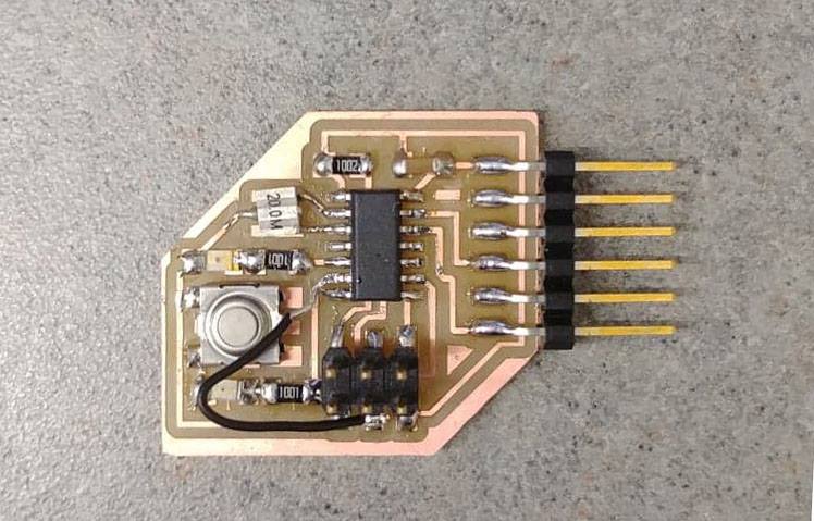
After giving up on my own, I went to office hours held by the TA Jackie and came to realize that my board from week 3 was not working correctly. Jackie told me that the programmer LED should become very bright when plugged into the FTDI cord. This was not the case, and instead, was very weakly lit
Thus, I used a multimeter to check for any links between connection that should not exist. Next, I verified that all the solder joints connected to the board. This involved placing one probe on the chip joint and the other on the board. By doing this, I was able to identify one joint not connect. At a quick glance, Jackie let me know that my soldering on my board is not ideal. She said it looks like the solder is raised above the board, but, instead, should be clearly adhering to the board. To solve this problem, the soldering iron should be touching both the joint and the board for equal heating distribution. Thus, allowing for the solder to want to adhear to both the joint and the board. Following these instruction, I went through all the joints and reheated them by making sure to touch both the joint and the board with the soldering iron and leaving it there until it was clearly connected to both.
After resoldering all the joint, I then re-tested out the board. There was still an issue with communication with the board. So, I again went through the circuits of the board to find any additional issues. To my surprise, I realized that one of MOSI communivcation line did not have a link to the attiny45. Thus, I had to conduct surgery on my board to fix this issue. Basically involved adding a wire to connect the two joints.

Following all of these fixes, I reconnected the board I was able to communicate with my board. Also, while conducting these fixes, Jackie was helping me make my computer communicate with my board since she also had a newer Macbook with High Sierra that was able to communicate with the board. She had a macbook adapter by Mokin and a FTDI wire purchased online. I deviced to purchases the same items to since hers seemed to work.
When Jackie was helping me setup my computer, we had to install a couple things within terminal. Such as: Homebrew, AVR-GCC, and AVRDUDE. Then, I followed Neil's intructions which involved the commands summarized below.
make -f [makefile_name].make // compile the .c code and make hex file make -f [makefile_name].make program-usbtiny // sending program make -f [makefile_name].make program-usbtiny-fuses // sending program and set the external clock (only need to use once)
All of these commands were successful as indicated on Neil's tutorial. However, I was not able to run the python code. Once I got to this step, I no longer had time to work on this project, so I decided to purchase the mac adapter and USB FTDI cable to futher figure out the problem at my own house. Currently waiting for these devices to arrive. TO BE CONTINUED.