All of it coming together...
Early Thoughts
I originally thought about building a drone that would stop over a delivery zone and fall to earth gracefully. However, I realized that every time my drone fell, it was likely to break and I would have to mill another set of circuit boards. While I got better as this class progressed, it was not my strength.
Link to my Final Project Ideation page
Convertible furniture
I have moved about 7 times since college. Each space I have lived in has been unique with its own set of furniture needs. And moving to Cambridge, space is at a premium. So I decided to create "smart", convertible furnuture. The piece is a side serving table that if required, could convert into a dining room extension. The shelves will extend and become the seat benches for the table extension. It could also convert to a desk by just extending one desk. While I originally thought about using a stepper motor to move the benches, my lesson from Machine Week is that programming those motors is not trivial and also moving aover 5lbs of wood, would take a lot of power. So in the end, I decided to control a solenoid that locked and unlocked the bench.
Current commercial inspiration - ORI
Click below for video.

Compared to my architecture bretheren in my section, my drafting skills are laughable. Here is my slightly embarrasing early sketch:

Weekly Projects Used
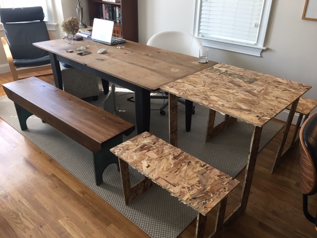
I used the make something big week to do a very rough desigin of my table with the OSB board. It was not structurally sound.
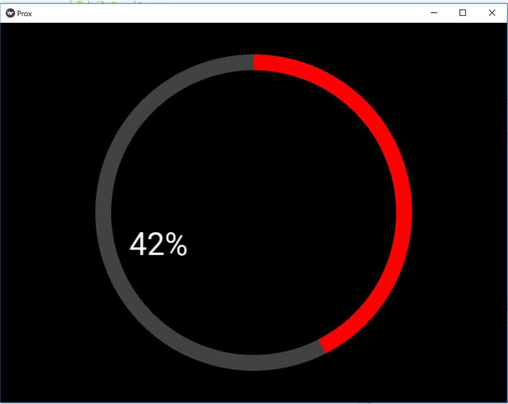
I also used my input and interface week to start work on my proximity sensor.
Getting my Sensor board to talk
So I took my sensor board from Week 12 and added a 2x2 header so it could talk to the eventual board that would control my solenoid. I used a modified python code to listen to the board sending out framing signals and a proximity reading. For simplicity, I changed the code to send out an 'h' for high or an 'l' for low depending on the proximity reading at a software defined threshold. In the bottom right photo, you can see the '108' for 'h' and '104' for 'l.'


Click the below picture for the complete KiCad file including PNGs to cut the sensor board along with the small seperate board that just has the LED and photo transistor.

Creating my solenoid board
I had to learn a little more electrical engineering. I had a 12V, 0.8A solenoid lock (Cost: $12) that I needed to control with a 5V signal from my ATTINY84. There was a great blog post with video of how to do that on the website NerdKits. I also looked at these two blog posts to make sure I was applying the correct logic to a solenoid: 1. StackExchange post , 2. BC Robotics.
In the end the jist is that you power the board with the necessary 9V-12V. Use a voltage regulator to then power the microcontroller. The micrcontroller then uses its 5V signal to control a gate on a mosfet that basically connects the solenoid to ground to give it the voltage to activate.
Click the below picture for the KiCad file for the sensor board.

Networking two boards to talk via RS-232
I also created a button board with networking capabilities. The idea was to also be able to control the solenoid with a button if necesarry. I set the up the button board and the proxmity in serial. I did get both to talk to the computer in turn. I used the term.py program to send signals to the computer via FTDI when I ever pinged them by a Node ID. You can see the framing signals and the 'U' or 'D' from the button board, interspesed with the 'H' or 'L' from the proximity sensor in the picture in the below left. I then tried to connect both to my main solenoid board and had the solenoid board ping them in order. However, I just couldn't get the solenoid board to listen at the right time to each of them. I spent a whole afternoon messing with the code, loading and reloading all of the boards. I got some good practice with C, loading and reloading three different boards. I felt I was close, but had to call it quits to stay on track to finish my project. I did revist this periodicially over the week, but never quite suceeded. The picture to the bottom right are all three boards. You can download the the failed code for all three boards as well as the associated KiCad file for the button board.


Finishing the electronics
Even with my setback with networking, I really got more confident with my microcontroller coding abilities. While I I am still limited in what I can accomplish with C, I feel as if it is less of a mystery. In the end, my light sensor board still talked to my solenoid board via Serial. However, it just kept on sending and the solenoid would just listen during the while loop at certain times. I connected a button directly to the solenoid board. The solenoid would unlock whenever the proximity sensor sensed a change in being close to something or no longer being close to something. Bringing it back to my table - if my serving table was brought next to my dining room table, it would unlock the benches to be pulled out. If it was moved away from the table, it would also unlock to allow the benches to be pushed in. There was a five second window to move the bench to the next position before locking again. The button could also be activated the unlocking mechanism if you wanted to push in and out on demand or needed more time.
Final C Code and Make Files:
Final boards all together including a power board to connect the two solenoid boards:

Designing the table
I created the table in Rhino. I did it just in the nick of time, since my 90 day trial expired the day before the project was due! I did my first rough draft of it. You can see a picture of that below. However Paloma, our TA, really helped me finish up the file and get it started in Mastercam. I worked through Mastercam, doing my best. I originally made scallops in my design, but was told by Chris and Jen that I just need to put in points in my rhino file at corners and drill there. I got a preliminary set of tool paths that worked. However, when I got to the Architecture Wood Shop in N51, the shop monitor on the weekend really helped me out with fine tuning my file including putting the correct speeds. You can download the full file below and see the different settings he used.

Milling on the Onsrud
I bought this 4'x8' Russian Birch Plywood from the Architecture Shop. It was a little pricy (Cost $125), but I thought it worth it. The Wood Shop Chief Chris said the North American Birch plywood would not hold up struturally as well, especially if I was going to use it for benches and it was to hold a human's weight. I filled up some of the spots with spare pieces of wood. They came in handy during construction, but one piece was a little small and we had to stop the machine when it popped out. Thank goodness it was towards the end of the cut, since we had to quickly rerun the G code on the leftover pieces to restart the Onsrud.
3D printing the sensor housing
I printed a little housing for my light sensor. Being finals week, the three Shindoh's in the architecture shop were all in some state of disrepair. Looked like a lot of jobs were going bad due to jammed nozzles. My neighbor actually built his own 3D printer with a kit. He even added his own heater bed, thus creating a machine for about $300 total that rivaled the thousand dollar+ machines. It is also easily scalable if he wanted to make the bed space bigger for large pieces. Here is the simple STL file I made in Fusion.

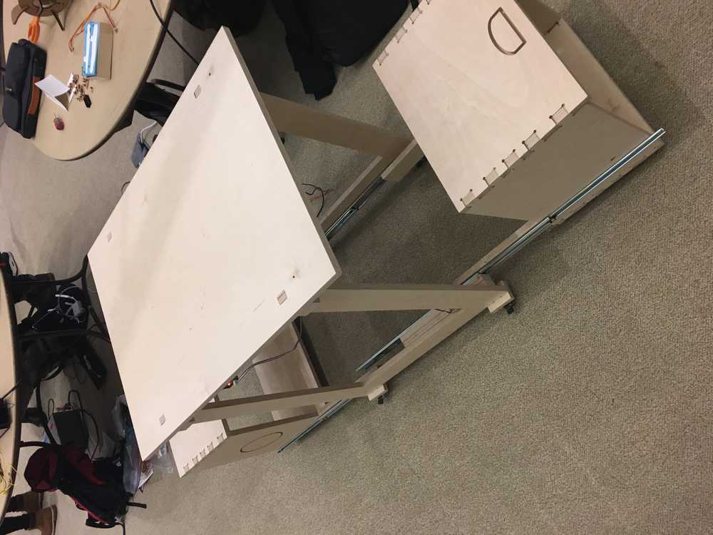
Putting it all together
Professor Neil Gershenfeld warned everyone not to put integration to the last minute. I really planned on finishing earlier, but I took a couple days longer finishing my electronics than originally planned. So I had to enlist the help of my amazing girlfriend to come to the shop and help with some of the final contruction and troubleshooting some final design elements. We connected the seats to the table with simple drawer tracks (Cost $20/pair). I also added wheels to the bottom of the table (Cost $2.50/each).


Video of my final presentation (click to open up the video and hear the audio):
Next Steps
I tested my circuits with 9V going in with the hopes of using a 9V battery. However, when I hooked it up to a battery, the circuits started doing funny things. I did not have enough time to troubleshoot and learn the nuances of using batteries as a power source, but will need to if I plan on using this practically. I would probably have to add an on/off switch to the circuits to save power. Obviously, I also would like to have done a much better job with the packaging of the wires. Additionally, I kept the table solely put together with press fits since I was moving this to and from the Architecture Spaces, Wood Shop in N51, and the Media Lab; and I was taking it apart and putting it together each time. However, to make it more stable I would like to add some cam locks and nuts at the joints. Finally, I plan to sand and finish the table with the goal to actually use this in my house.
Some final thoughts:
My application to MIT's Leaders for Global Operations Program stated I wanted to further the adoption of additive manufacturing in conusmer end-products. I will actually be heading to General Motors next semester for a 6 month internship with their new Additive Manufacturing Team. I took this class to better understand the workflow of digital fabrication. I learned that the current state of making almost anything has very few standardized workflows. The information revolution required interoperability and standards to be successful. A potential digital fabrication revolution would need similar dynamics. Hopefully we can find a way to get there!