This week, we learned 2 types of cutters —— vinyl cutters & laser cutters. I had previous experience with the laser cutters from my former architectural studios, but I need to practice more for the CAD part, as well as operating the machine. My previous problems with laser cutters are: in the Rhino CAD, some geometry are not valid (not intersecting properly, or overlapping lines); sometimes the focus of the machine was not right; setting the power and frequency not efficient enough.
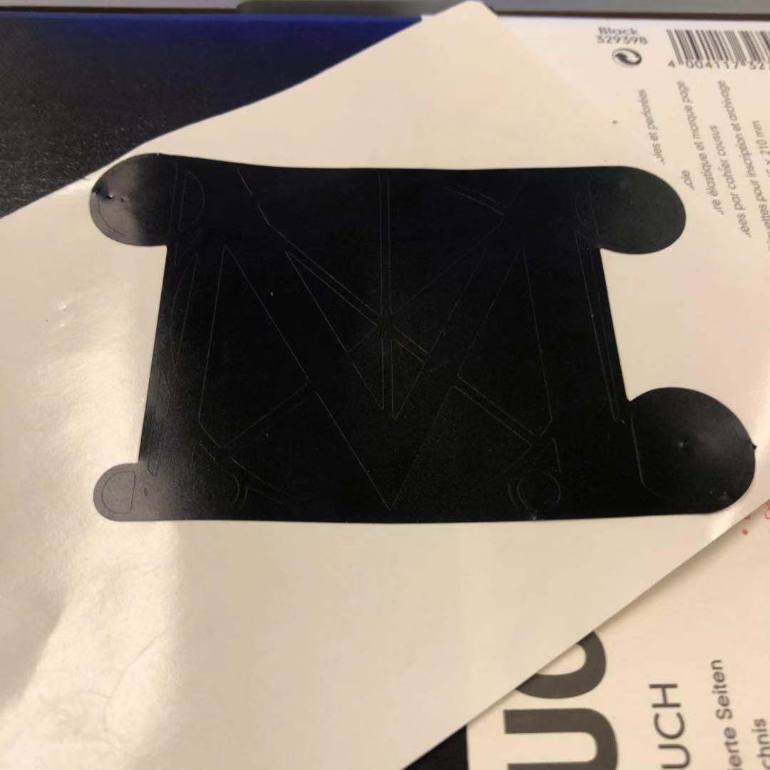
During this week, what I did include: making a press-fit construction kit, cutting a computer sticker, testing out bending kerf, and characterizing the laser cutters.
The first step is to measure the kerf. The laser cutter I was using for this project was the Epilog 120W. To measure, I cut a square and measure the difference between the outer border of the cutout part and the inner rim of the hole using the caliper, and then divide it by 2. For the result, the kerf is 0.0118 in.
I then used the caliper to measure the thickness of the corrugated cardboards, which were bought from Blick. Their thickness is 0.148 in
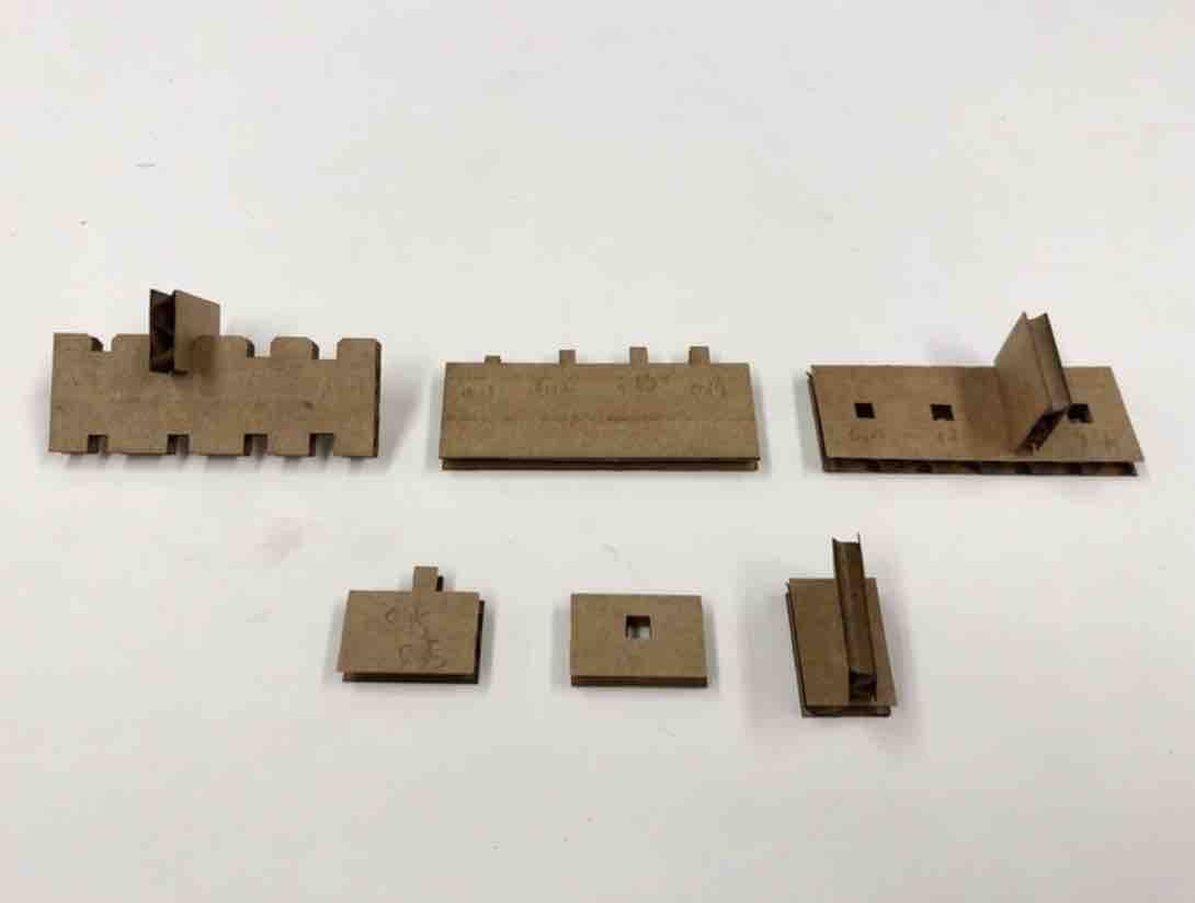
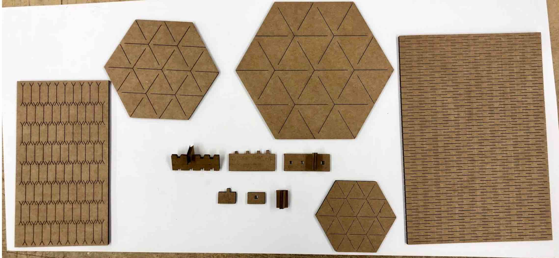
The next step is to test out the dimension of the notch for the kit. I laser-cutted notches and joints in various sizes. The notches have the width of 0.11 in, 0.12 in, 0.13 in, 0.14 in. I also cut half of them with the 45-degree chamfer. For the joints, I also have the same dimensions. What ended up happening is that the joins, which are shown as the right most device in the image, is not strong enough to hold up, because the connecting part is too small. Thus, I decided to use the notch connection for my project, as shown on the left of the image.
The result is that, the width of the notch needs to be 0.12 in.
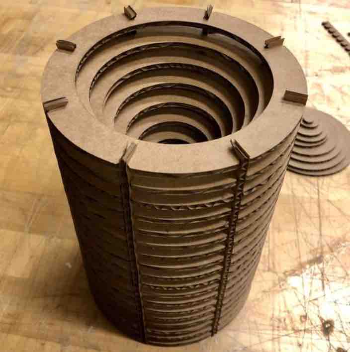
I am really interested in the offset function in Rhino, and are intrigued by the visual effect of layering offsetting 2D shapes together. Thus, I decided to create a cylinder, whose volume is created by the circular planes, with offsetting circular apertures.
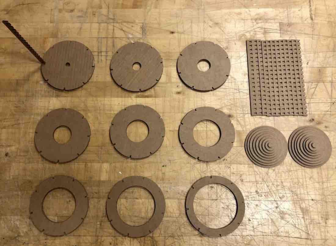
Here are all of the components of my kit. I have 2 of each of the 9 circular rings, with different sizes of cutout circles. Each ring has 8 notches, and I cut 8 of the long strips to assemble the cylinder
The long strips have 8 notches on them, and the width of 0.5 in, and the each notch is 0.25 in away from each other.
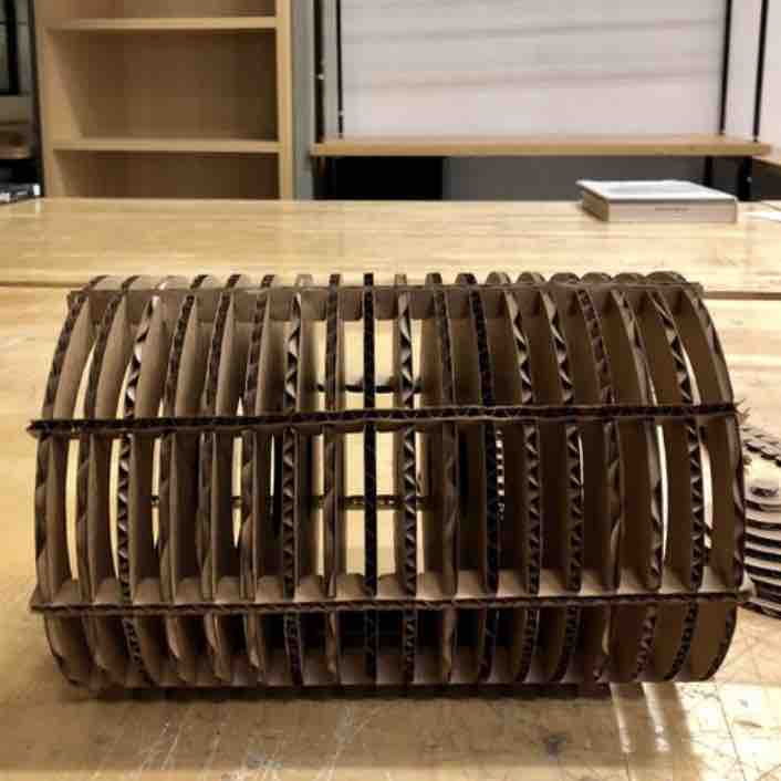
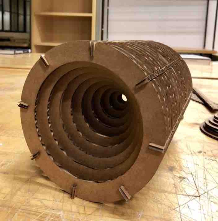
This is the final object. To me, what was really cool is that the strips that helps to build up the volume fit in perfectly, so that the side surface of the cylinder is still flat and uniform. The cylinder can even roll smoothly. Moreover, I like the visual effect of its twirling center as we rotate the object. I also like the contrast between the concrete volume, when it is standing, and the seeing through layers when it is laying on the table.
What I could also consider and improve in the later projects include: the assembling process was still kind of hard, as some parts are harder to press in, and I was afraid to press them hard because they are so thin. Also, as we can see, at both the top and bottom, the strips still stick out because of the very nature of the notch I chose to uses, but I wonder if there is a way to make them disappear.
To explore more about corrugated cardboards and their use to transform from 2D to 3D, I tried to cut little samples of patterns that can be bent to create a curved surface from a sheet of flat materials. However, I did not chose to incorporate the bending sheets into my project, as I was not satisfied with the potential way to connect them together, as it will obstruct the uniform pattern on the sheet.
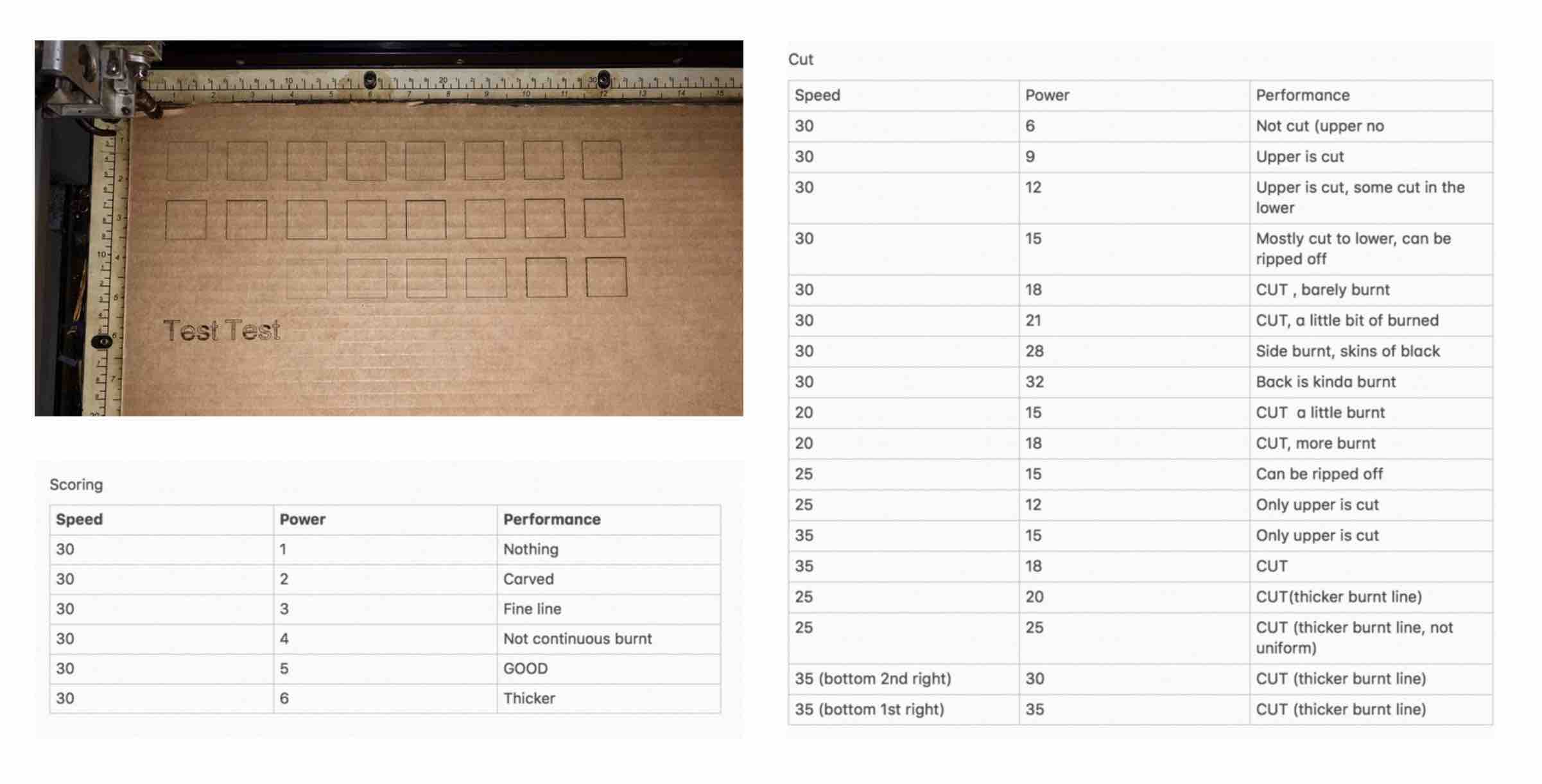
I performed the testing on the Epilog 75W laser cutter in arch shop. I tested cutting, scoring, as well as raster as the outline of the squares. Here is the `testing observation, reading from left to right downward.