This week, I learned how to use the ATTiny to drive the servo motor; I am hoping that I can use either servo motor or DC motor in my final project of Opt art sculpture.
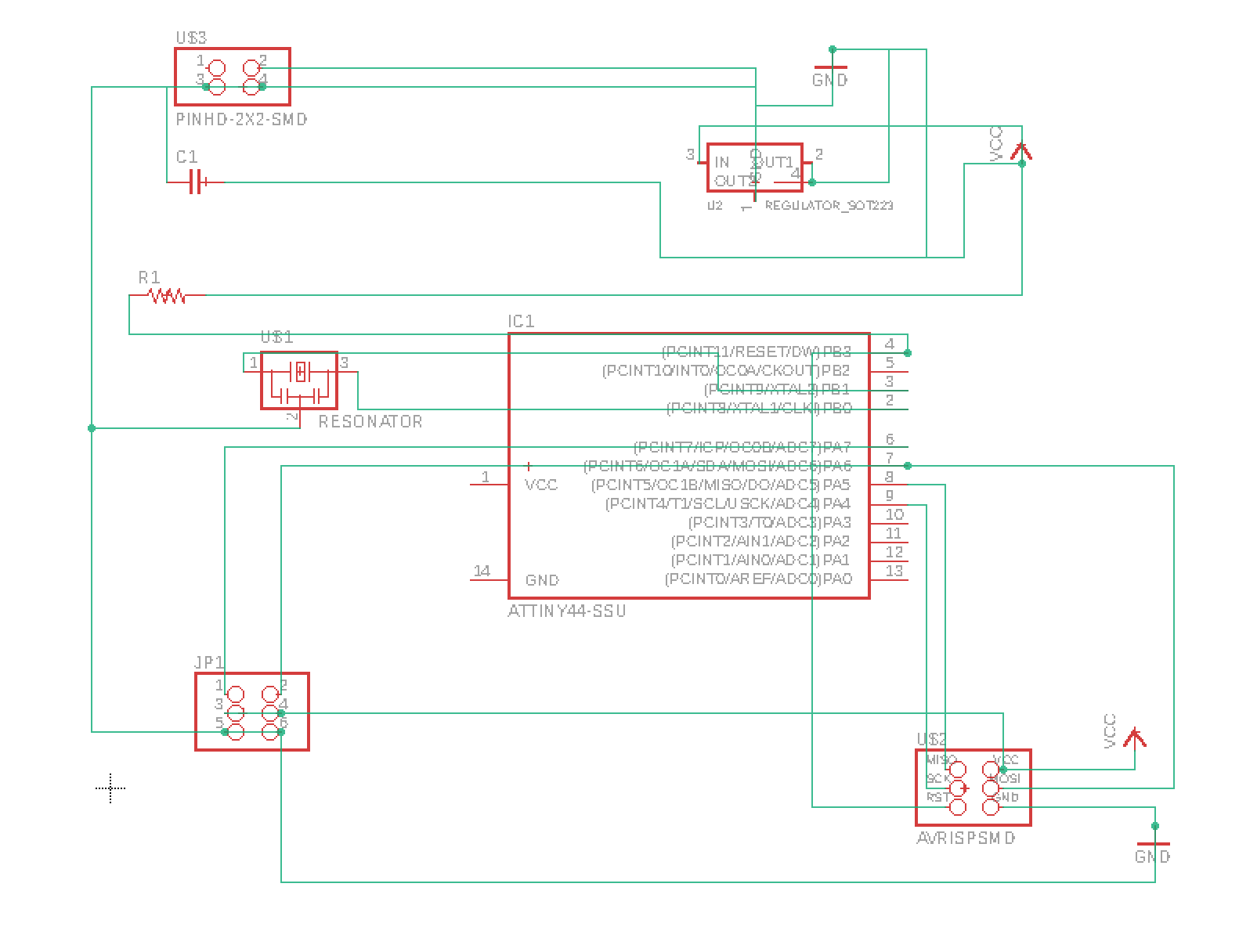
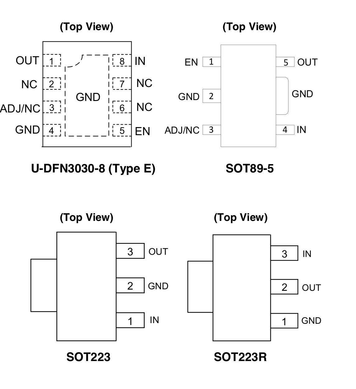
When designing the board, I was not sure how to connect the nets and the routes to the regulators, as the symbol in EAGLE is a little bit confusing. So I went online to search for the data sheet of the component and then fixed the connection. Also, what I designed in the first time did not work, as the resistor is not connected to the VCC… So I went back and made changes to the design and remade the board.
When creating the PNG for milling, I tried again the python script but it was still not working…
I paid much more attention in the making process.
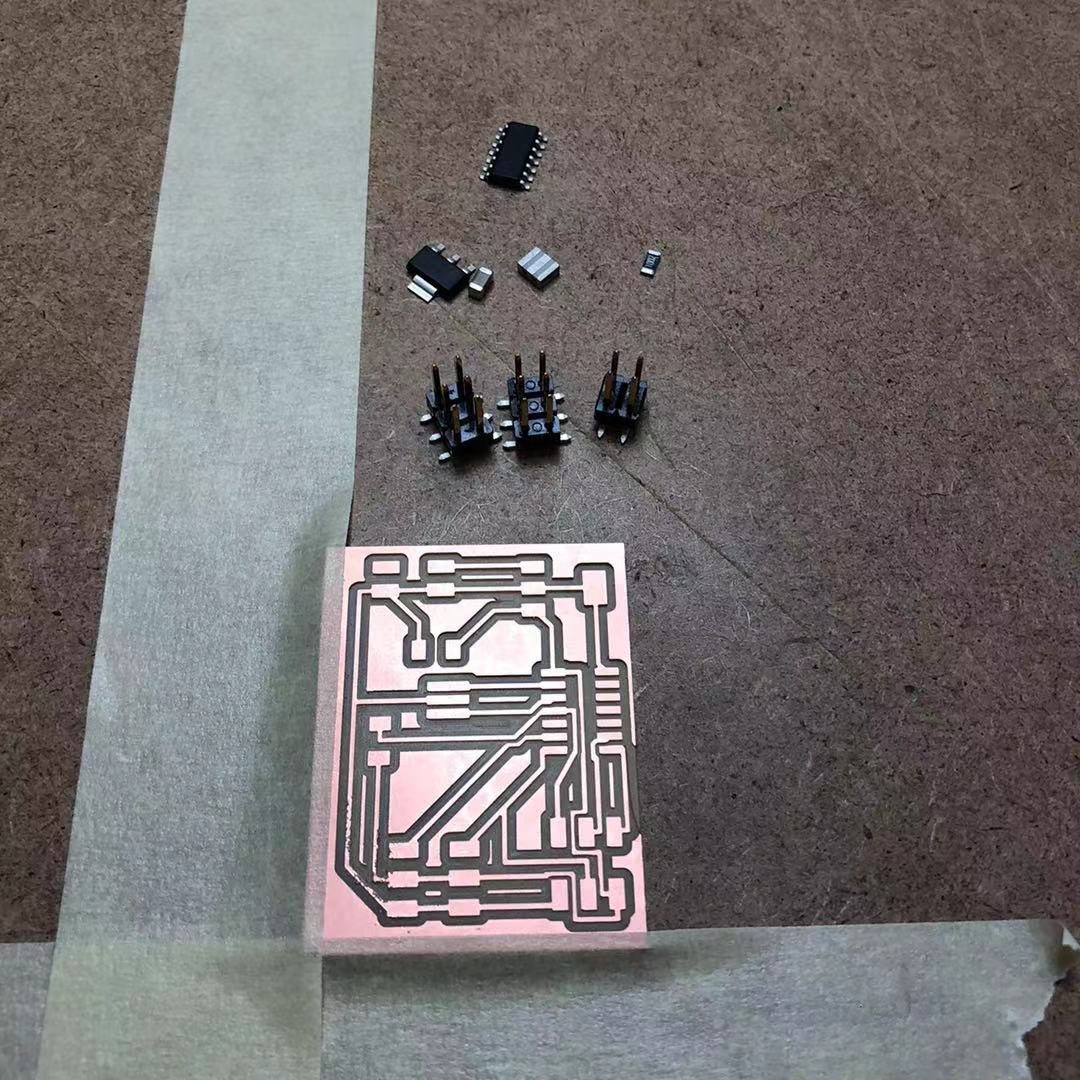
The milling process was still the same, and again, I felt that the preparation process became faster than before.
After milling each board, I again compared the boards carefully with the original images and see if the traces match up.
Then it came to the soldering part. Starting from the smallest parts on the board, I practiced more on the technique of reflow when I need to solder the resonator onto the board.
The rest of the solder went well.
I read online on the tutorials of driving the servo motor in Arduino. I looked into 2 libraries: Servo and Software Servo, and realized that there is not that much difference. So I sticked with the default Servo library that is already installed. And here is the screenshot of the program I wrote on setting the pin, and then increment the angular location of the motor.
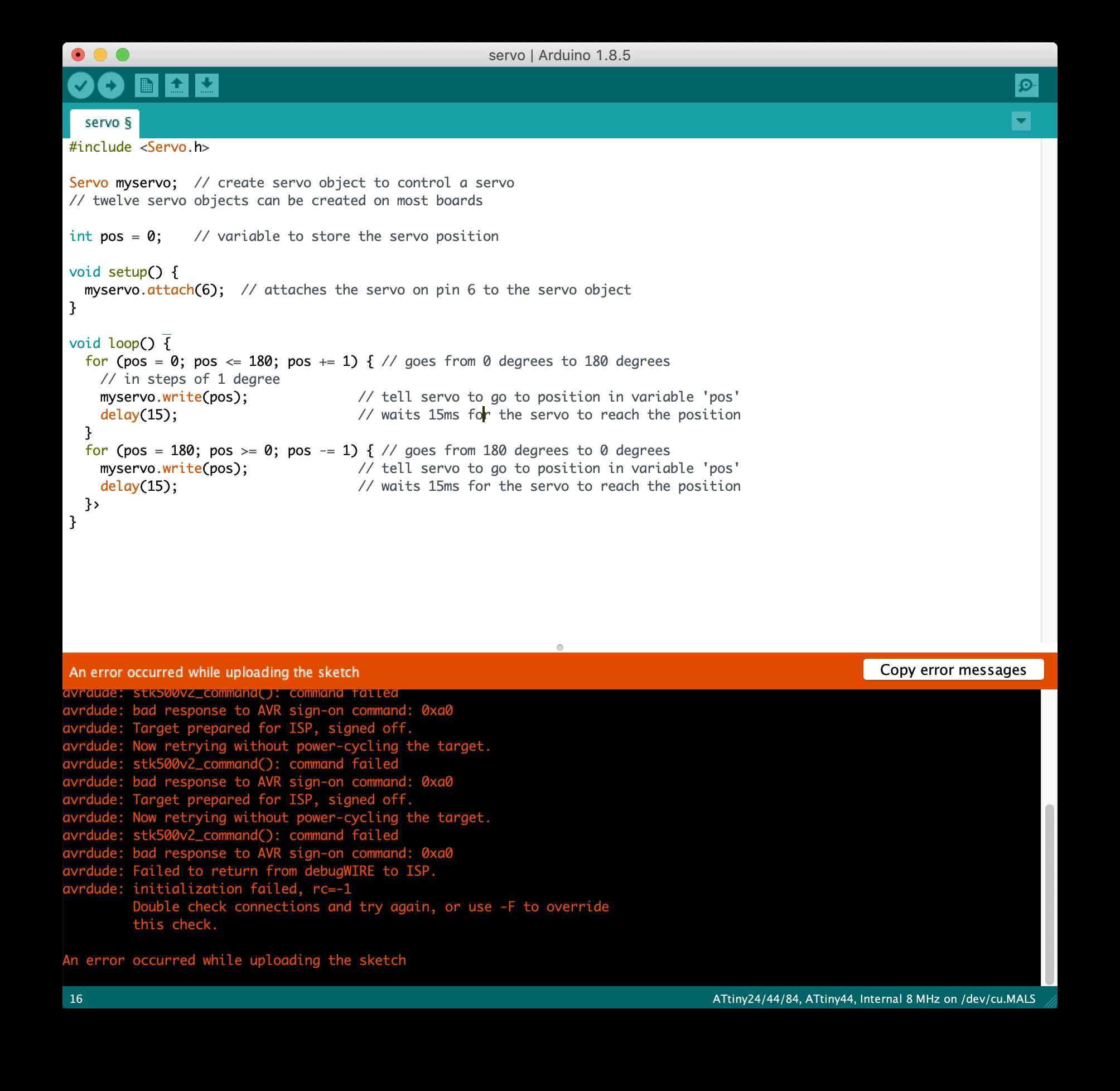
What happened at the beginning was that for some reason, I had to reinstall the AtmelICE.kext on my Mac, because the permission was denied again. Thus, I turned off my firewall and then re-installed it. Then, when I tested my first board, it gave me the RC=-1 message, and then I remade the board…
When it was done uploading, the motor started to rotate!