The assigment for the machine design week is to actuate and automate a machine as a group based on Jake Read's machine write-up. As a group, we decided to build a machine that can
3D print chocolate sculptures.
DIVIDE AND CONQUER
We divided into 5 groups, (1) machine design (2) hardware (3) electronics and software (4) extruder (5) camera, and we worked on this in parallel until Tuesday when we started putting everything together.
Implication: We want our x-axis to be shorter to make it sturdier
Protecting our motors from chocolate
We do not want our motors to come close to the chocolate that has been extruded, as that would damage the motors (and make our chocolate less delicious)
Our machine will not have automatic collision detection (we are not that advanced) so we must design the machine so that the motors are safely positioned away from potential chocolate
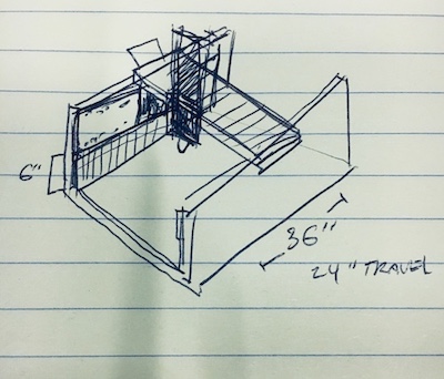
We started by using the provided RCT gantry as the X, Y, and Z axes, and worked on how to compose the axes.
Original plan:
Use 2 lengthened Y-axes and position them vertically
Put a shortened X-axes on top of the Y-axes, so that the extruder can travel between these gantries
We thought this would establish the best stability for chocolate extrusion.
ISSUES WITH ORIGINAL PLAN
We encountered parametric issues when attempting to shorten the x-axis from the original design -- we were unable to simply shorten the part, or lessen the number of tabs.
The issues with the parametric settings caused us to reconsider our design.
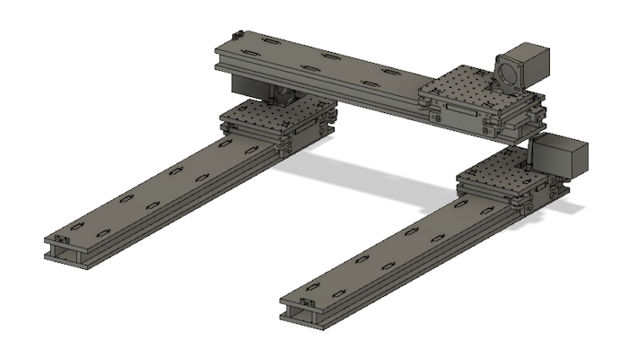
NEW PLAN
to work with the parametric issues & constraints imposed by the original design:
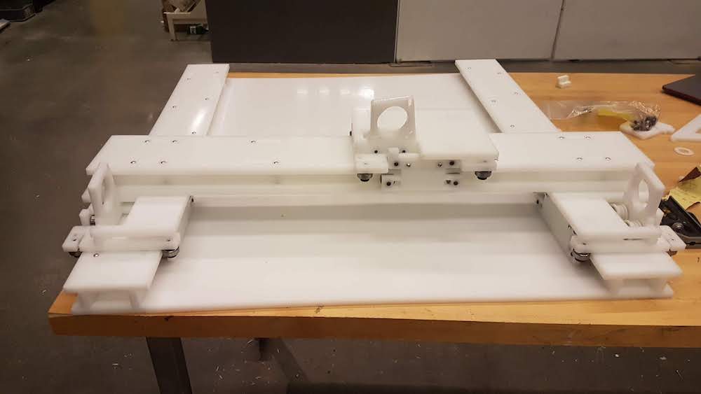
2 mirrored Y-axes positioned horizontally (laying on their sides)
Each y-axis has a motor
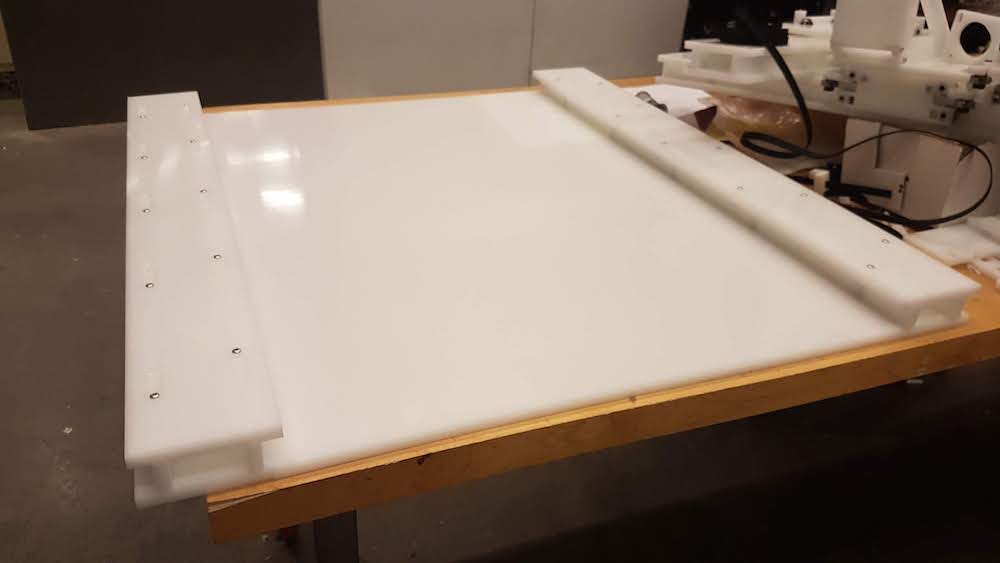
Brackets extend above the y-axes to elevate the x-axis that sits between them
1 extended (wider) bottom plate between the Y-axes to accommodate the horizontal positioning of the Y-axes
Z-axis fits on top of X-axis
TASKS
shorten the z-axis without working with parametric settings (note broken parametric settings)
This is necessary so that the z-axis can bear the weight of the chocolate in the extruder.
We chose to do this by using boolean logic to slice the starting axis design.
Design the base plate that sits between the y-axes
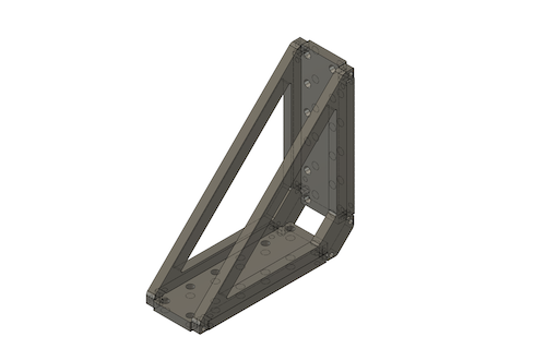
Design brackets that elevate x-axis above y-axes
Compose the parts
STEPS
We mirrored our y-axis component to create its mate
Challenge:
Connect y-axes with a base plate. The problem was that two separate components cannot be connected by one body (a base plate).
Solution:
We deleted the base plates of the y-axis components and put them into a new “base plate” component, which we then joined into one base plate. We reconnected this base plate to our y-axes.
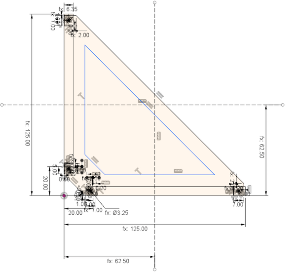
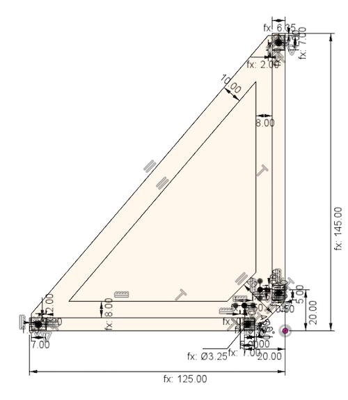
We went into the part’s creation history timeline in fusion to modify it in the following ways:
Transform its triangular shape to a rectangle. We modified the underlying sketch for the component
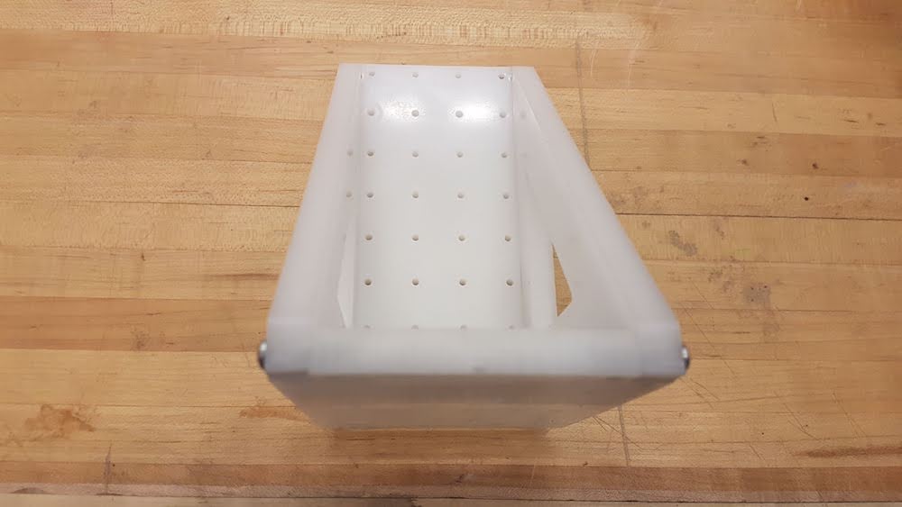
Make it solid without cutouts. The bracket was originally designed for aluminum, which is a more rigid material than our HDPE material. We removed the cutouts to provide more support for our HDPE brackets.
To save ourselves time, made the decision to not include all of the fillet’s from Jake’s original design. We did this knowing we ran the risk of imprecision at the time of cutting the parts.
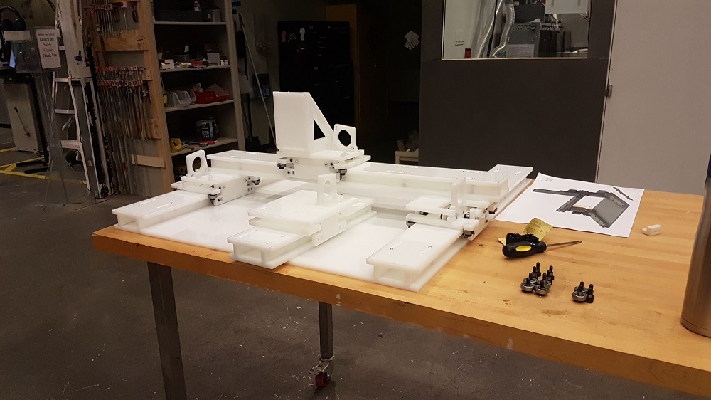
Throughout this process, much of time went to measuring parts and determining how large parts should be, how many holes they should have, etc.
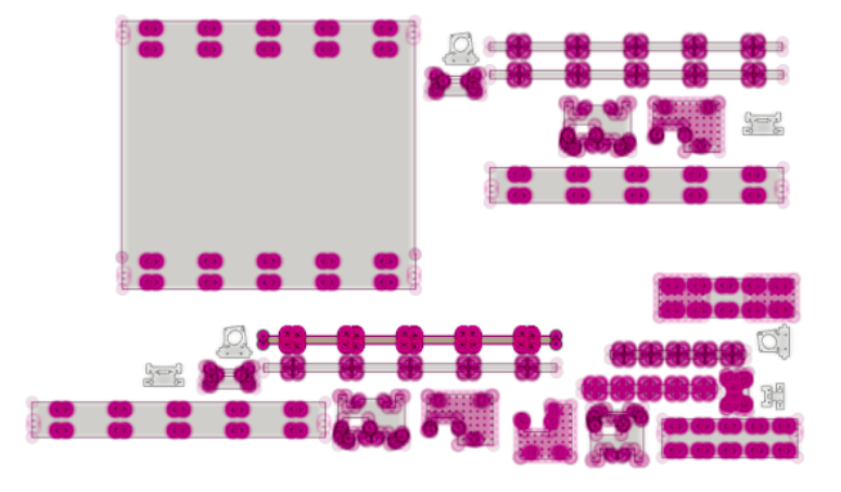
This is the final design:
Liz took the final model and attempted to flat pack the design using the script and did the following:
The Script did not run unfortunately
All of the pieces were flat packed individually and saved individually and it took a couple of hours
Sketches had to be created for each piece and saved as .DXF for V-Carve
Files were handed as a package to the Fabrication Team in folders for: X-Axis, Y-Axis, Z-Axis and Brackets
Readied the remaining files for 3D printing by saving them as .STL files
FABRICATION
The fabrication team took turns to design tool paths, watch over the shop bot and troubleshoot errors throughout the assembly process. We encountered the following issues and solutions while cutting:
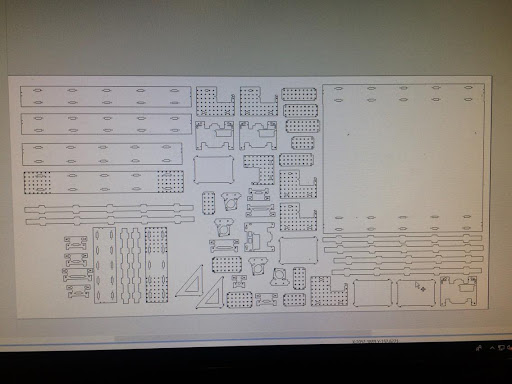
Tool Path Design and File Prep
Initially, the design team was having issues with the flat pack plug in, since they were mostly working on OS platform. They were able to flat pack some of it, but for the most part each piece was manually imported into the V-carve file.
That took some time to figure out and laying it out in the most efficient way possible.
Following the online tutorial we were able to get most of the settings right but we did encounter some issues. We believe the strange translation between programs and operating systems was causing some issues with joining vectors even
after we did the Join/Close vector command. We went back and forth between the tool path calculations to make sure all the vectors were closed, so we had to do that manually as well.
Selecting each individual circle for pecking tool path was a pain in the butt, but we found the most efficient way is to drag the mouse in the circle pattern and collect all around it while holding shift button. Someone please invent a
plug in or function to detect circle vectors in V-Carve.
Something that helped optimize the cutting was to separate inner cuts from outside cuts, so we had 3 tool paths total (in order) Pecking, Inner path, Outer path.
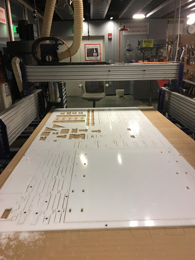
Cutting
We hadn’t done pecking on the shop bot before so we weren’t aware that the pecking depth didn’t need to be more than 1 or 2 per hole. Our initial setting for the peck depth was .75 mm which for a 12 mm cut depth was around 16 pecks per
hole. That took about 4-5 hours of cutting. For the later cutting we set it to be 6 mm per peck and that helped significantly.
We had several pieces that did not survive the first run, due to faulty tab settings and some dog bone errors. They weren’t appearing on the tool path at all since the material is 9mm thick, while our cut depth is 12. We had initially
set them to 1 mm, which did not appear to make a difference at all. Then 3 mm, which only appeared on a few of the pieces. 4 mm seemed to be the ideal since it left Just enough material for the pieces to not move, but also snap out very
easily without the need of external tools. Basically for tabs it would be:
Cut depth (12mm) - Materal thickness (9mm) + 1 or 2 mm.
Several pieces of web started to wobble due to tension form the machine and the very narrow amount of material between them did not provide enough support. This is the resulting cut in the web:
This also created some warping in the sheet which caused some of the outside and inside cuts in the smaller pieces to not be deep enough. We fixed this by doubling the spacing between the webs in V-Carve which provided enough support and
adding the tabs correctly
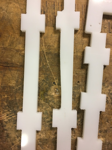
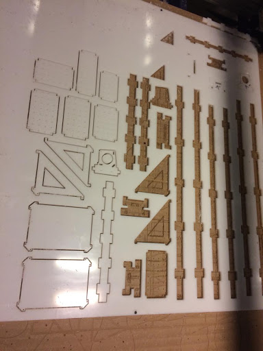
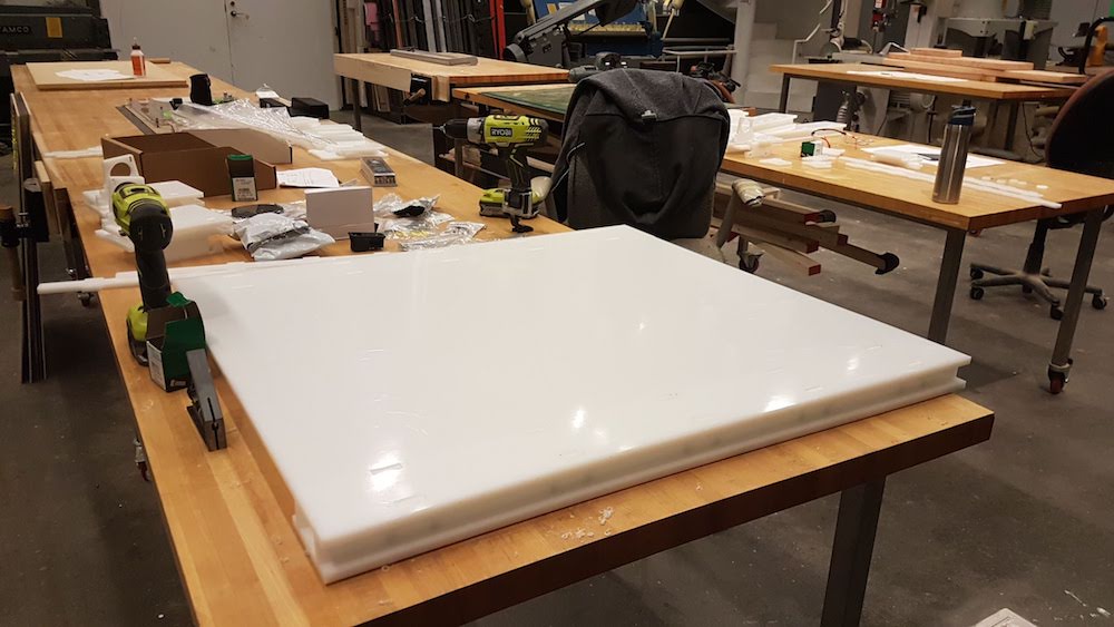
The cutouts pre-assembly:
Re-cutting
A useful way to keep track of Re-cutting on the same sheet is to save several versions of the VCarve file. Each new version contains all the previously cut vectors, for reference, but you delete the existing tool paths every new version.
Just remember to delete them under the toolpath settings and start fresh so there won’t be any confusion or doubling of tool paths during the cutting process. Ideally this is all done in the same session so that you don’t lose your
Z-axis if the shop bot is turned off.
3D PRINTS
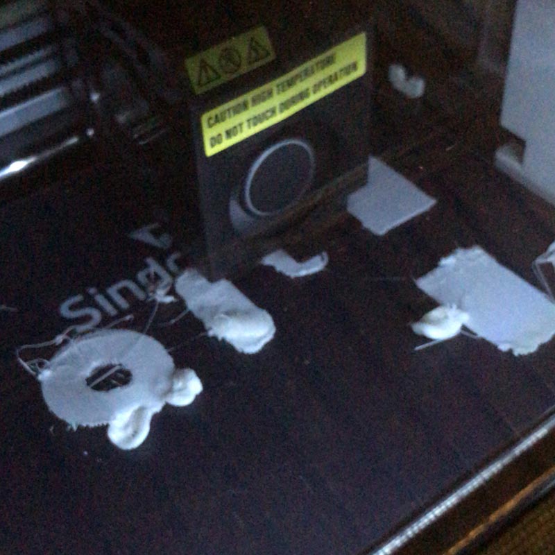
In addition to milling the board, some of the parts needed to be 3D printed.
We initially tried to print them all together on the same 3DWOX, but having a lot of small parts printing at the same time caused the nozzle to push everything around on the bed. We successfully printed two parts per machine.
ELECTRONICS
Our goal is to connect 4 stepper motors to 4 drivers connected to both a power source and a router, which is connected to a computer.
Take a look at our step-by-step process
Load code to the driver and confirm that the led lights up.
Solder the stepper motor wires onto the driver. The pairs should look like Red-B1, Blue-B2, Black-A1, Green-A2. If you've crossed your pairs the motor won't spin.
Solder the RCJack-45 onto the driver.
Screw the driver onto the stepper motor.
Solder the RCJack-45s onto the router.
Cut red and black wires to 40, 50, and 60 inches in length. Strip the ends. Solder eye loops onto the ends of the red and black wires. Remember black is ground and red is power.
Connect AC plug to power supply. Be careful here! Black goes to L (live), white goes to N (neutral), and green goes to earth (ground). Then, attach one black wire to negative DC output and one red wire to positive DC output. These black
and red wires should plug into a resistor board, which have many black and red wires emanating out of it.
Cut the flat wires and add ethernet cable heads to them. Make these the same length as the red and black wires. These are used to connect the driver to the router. There's a very handy tool that lets you cut, strip, and fit the head onto
these flat wires.
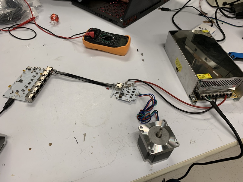
Here's what the initial set-up looks like (without the safety resistor). And, here the first recorded instance of the stepper motor spinning. Now that it's spinning, it's time to rinse and repeat on the other motors and start programming the
software.
Software
Installation
First, download the drivers at Silicon Labs. Then, clone the repo and install the node dependencies. This assumes you already have node
installed.
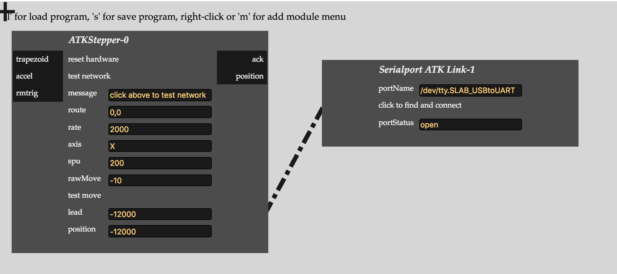
This code should load a browser that looks like screen.
Now, the fun part!
Writing the code
ASSEMBLY
Throughout the assembly process we had to disassemble several times after realizing certain pieces had to be taken apart in order to fit other pieces in. This could have been avoided if we had a step by step guide. Therefore, we decided to put
together a step by step documentation of how the parts go together for future reference.
Design
Check design documentation. We have two Y-axis, one X-axis, and one Z-axis and the end effectors attachment on the Z-axis. We need a total of 4 motors.
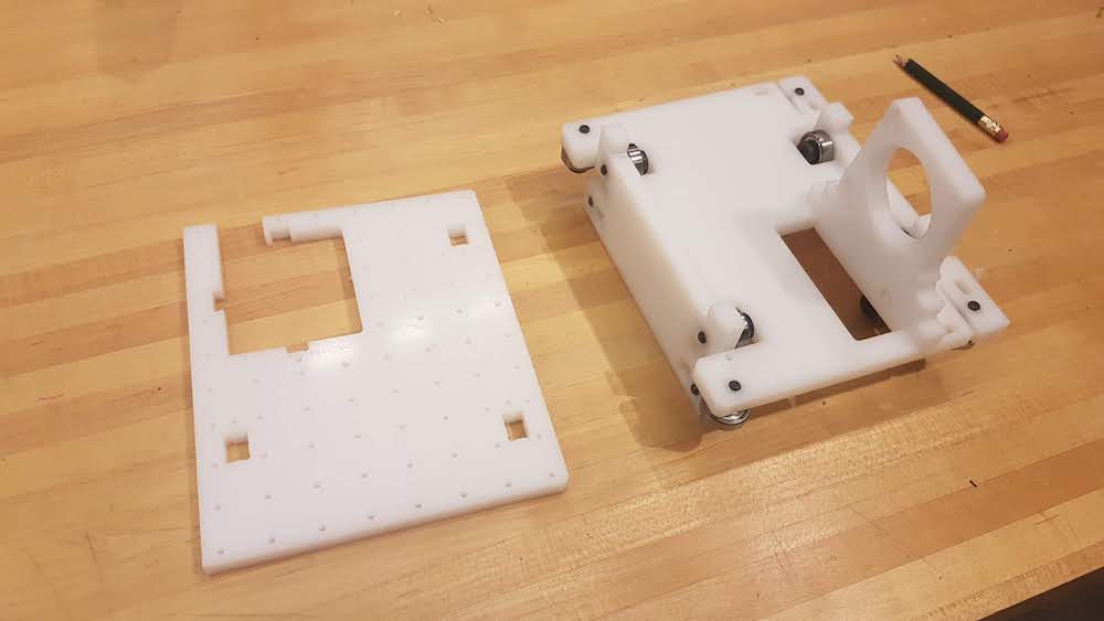
Step-by-Step Axis Assembly
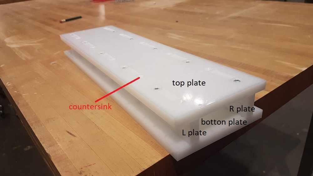
The axis assembly consists of 4 parts. The bottom plate, the top plate, and the two side plates(webbings). They should easily fit together and then be secured with screws.
Step 1: Find the 4 plates for your axis and fit them together.
1x top plate
1x bottom plate
1x R plate
1x L plate
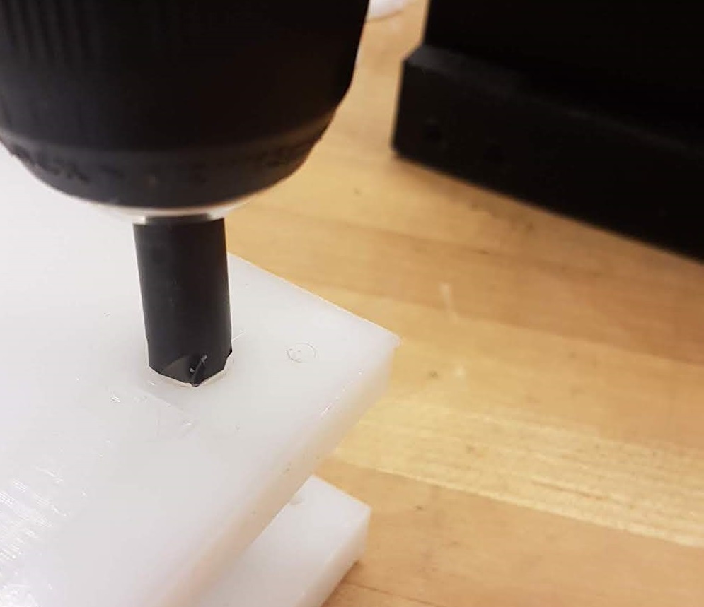
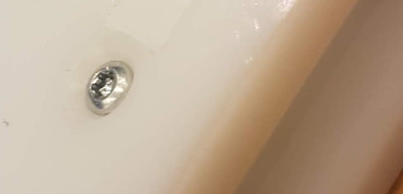
Step 2: Use a countersink drill bit to create counter for the screw to sit on. They are not needed for most of the parts, but we wanted to make them flush on the surface.
Step 3: Secure the parts with screws.
Y-axis base Assembly
The Y-axis is a little bit different. It has two guide rail systems (top and side (webbings) plates) attached to the bottom plate of the gantry machine. Press fit the pieces and screw them together. Countersink if needed.
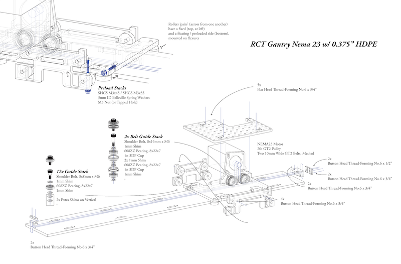
Step-by-Step RCT Gantry Guide System Assembly
Each axis comes with its own rail-slider guide system. Since we did not have a step-by-step assembly guide, we found ourselves putting them together and realizing that there were missing components that needed to be assembled first, so we
wasted a lot of time taking them apart over and over again.
Step 4: Gather the material for one rail-slider guide system.
1x Bottom plate
1x Top plate
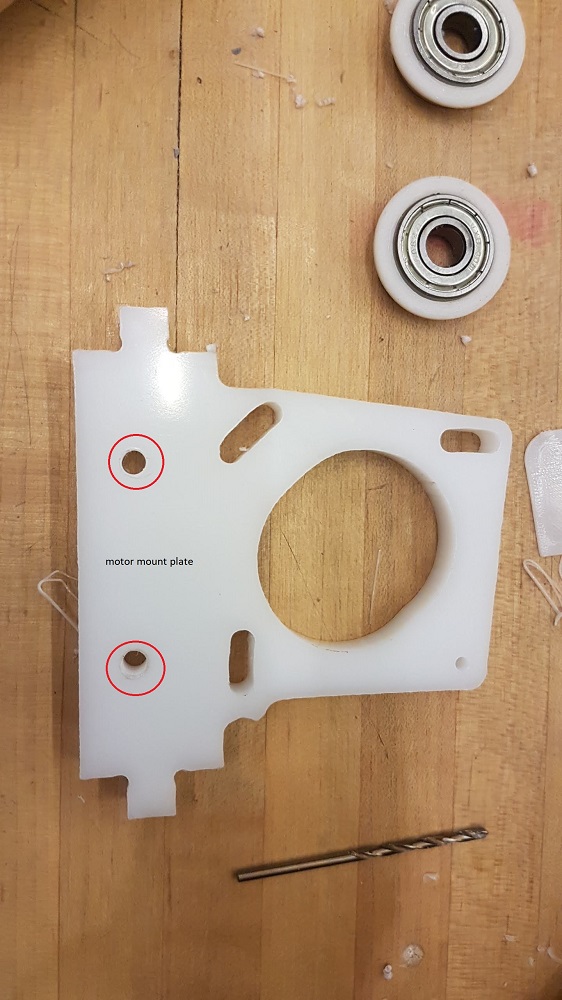
1x Motor-mount plate
1x Long side plate
1x short side plate
x12 ball bearings
x 12 8x8mm x M6 shoulder bolts
x 24 1mm shims
Resulting parts of the RCT Gantry Guide System should look like this:
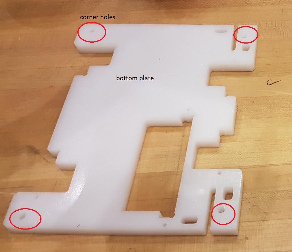
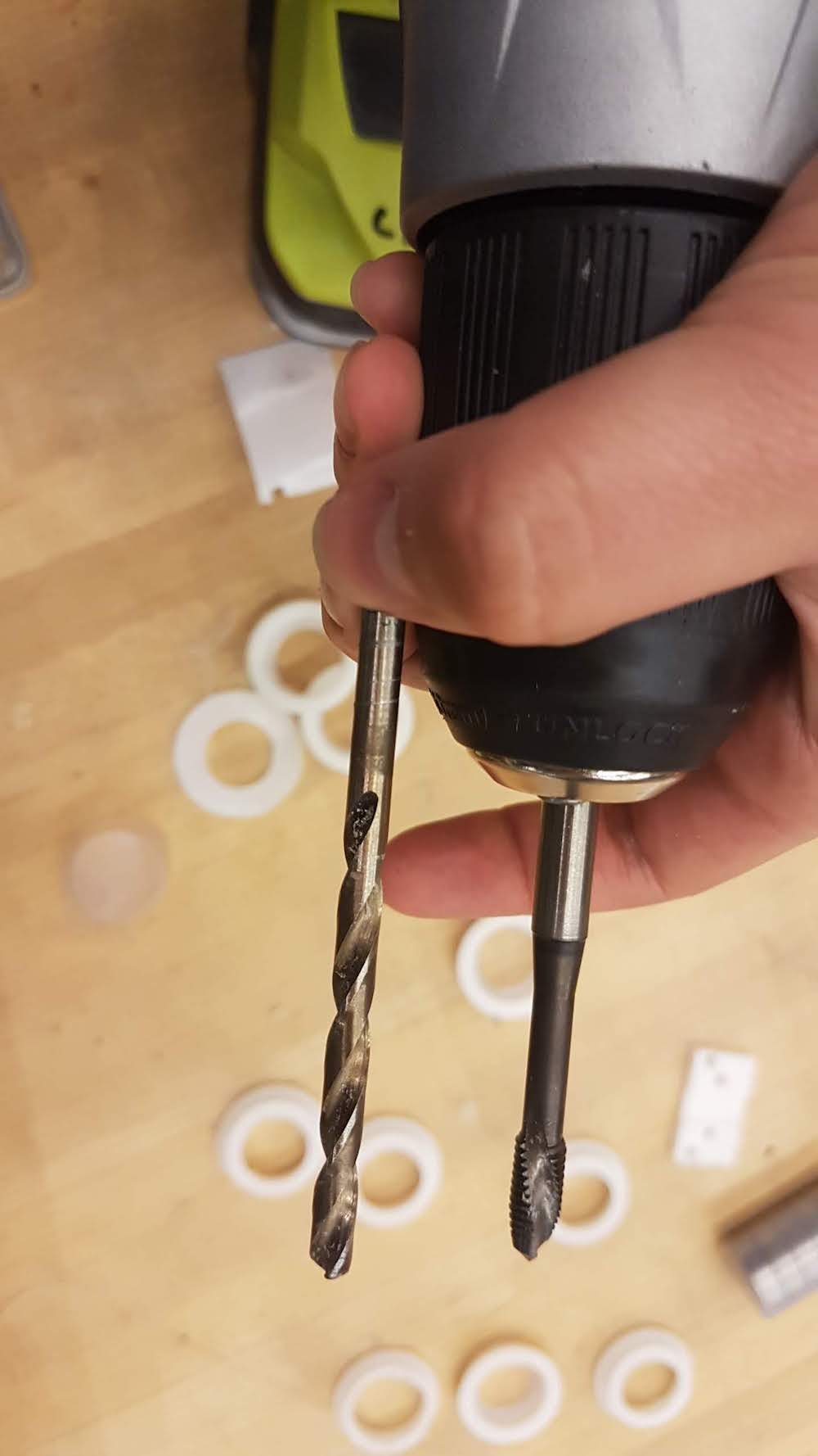
Step 5: Take the bottom plate and find the four corner holes. Those holes are not threaded, so you will have to drill and tap them to the diameter of the shoulder bolt.
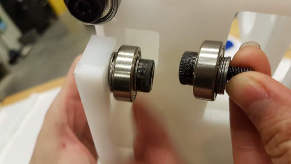
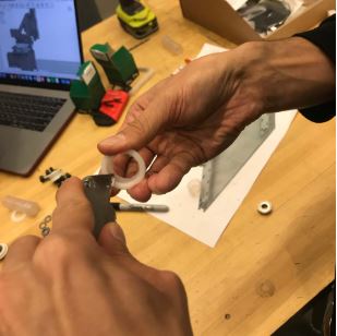
Step 6: Find x4 8x8mm x M6 bolts, x4 1mm shims, and a ball bearings. Place one shim in the bolt, then the ball bearing, then 3 more shims for spacing. Screw them on the bottom plate.
Step 7: Take the long and short side plates, x8 8x8mm shoulder bolts, x8 ball bearings and x8 1mm shims.
Put a ball bearing in the shoulder bolt and then a shim. Then screw them in the side plates.
(note: the 8 bearing for the side plates only require one shim on the side touching the HDPE)
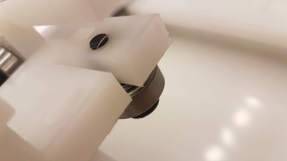
Step 8: Press fit the long and short side plates with the bottom plate and screw them together. You might want to drill a pilot hole through the material first.
Step 9: find the motor mount plate, drill and tap the two holes for threaded shoulder bolt.
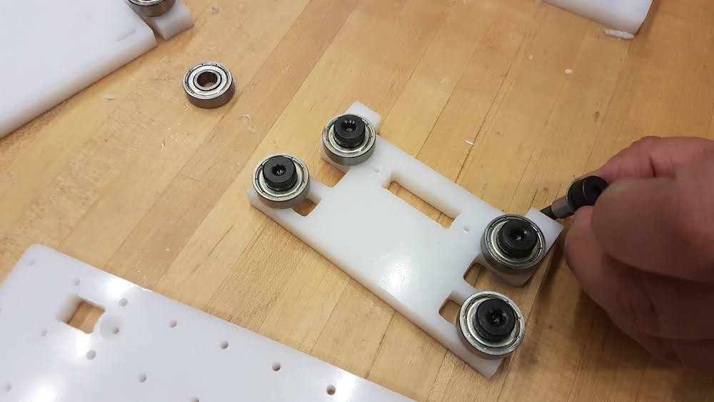
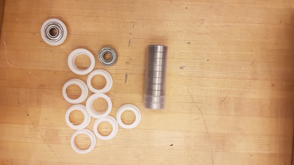
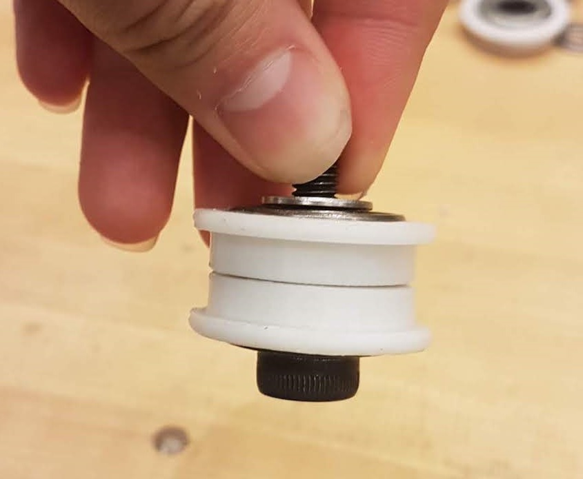
Step 10: Find the 3D printed bearing cup parts that you 3D printed. Snap the ball bearing inside the 3D printed bearing cup.
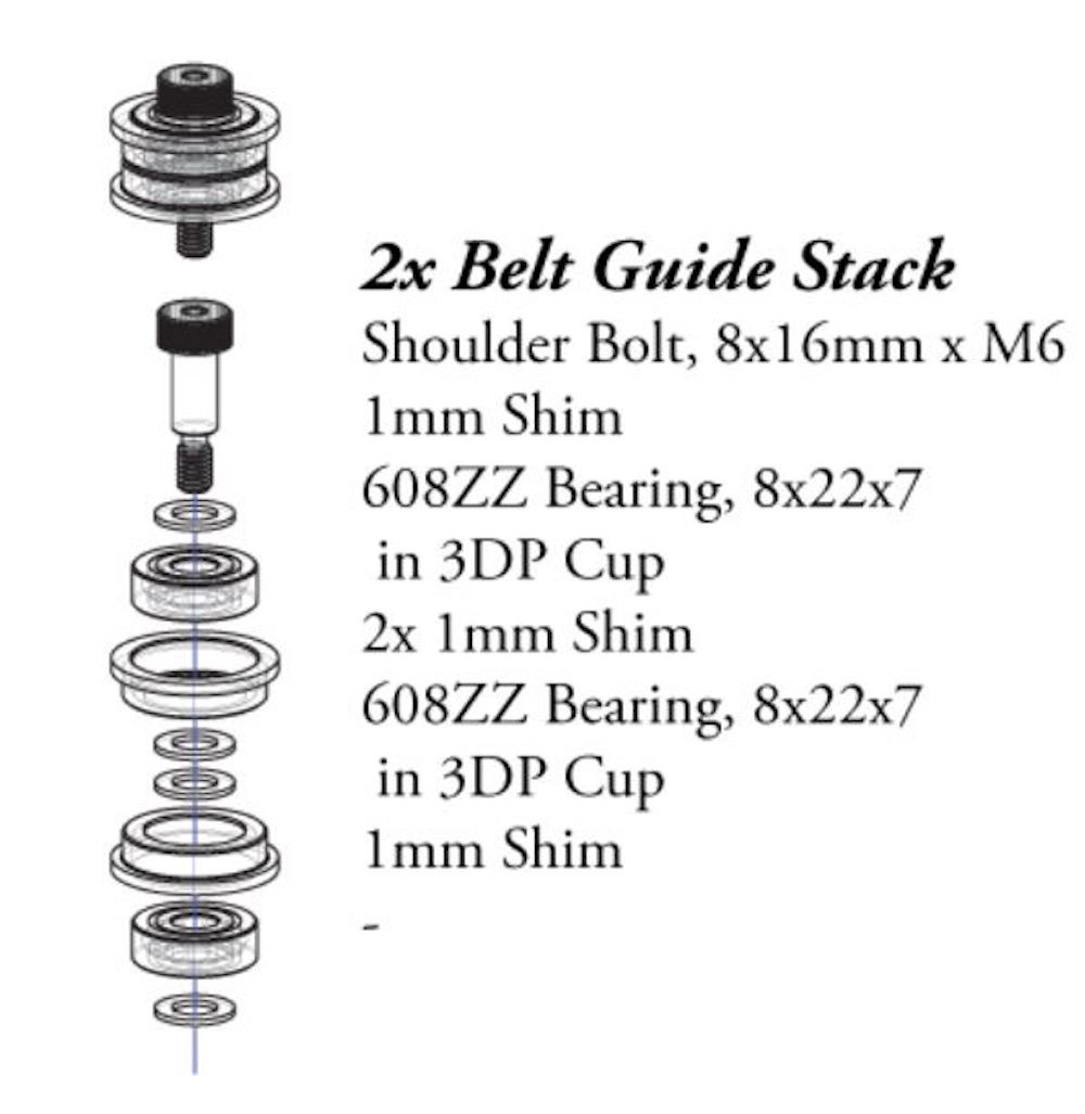
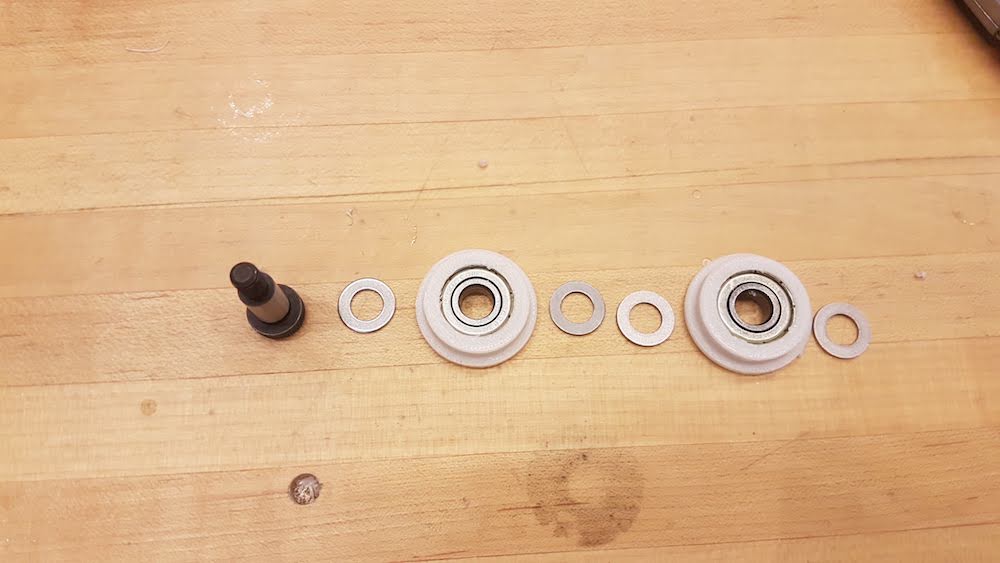
Step 11: Find 1x 8x16mm x M6 shoulder bolt, x4 1mm shims, x2 3D printed bearing cups, 2x ball bearings. Put them together as indicated below.
* The 3D-printed bearing cups were slightly too small out of the printer, so they needed to be carved out with a knife.
Step 12: Screw the belt guide stack into the motor mount plate as follow:
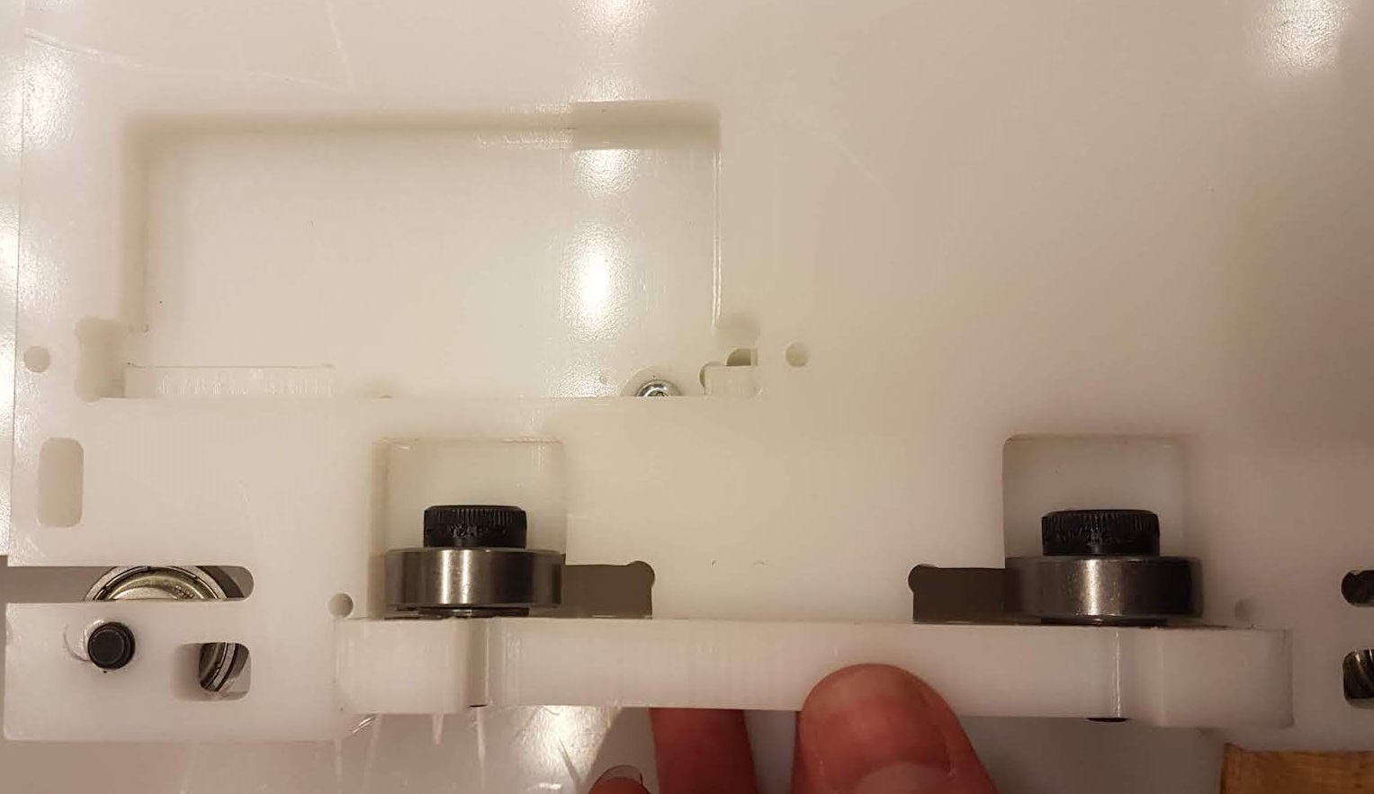
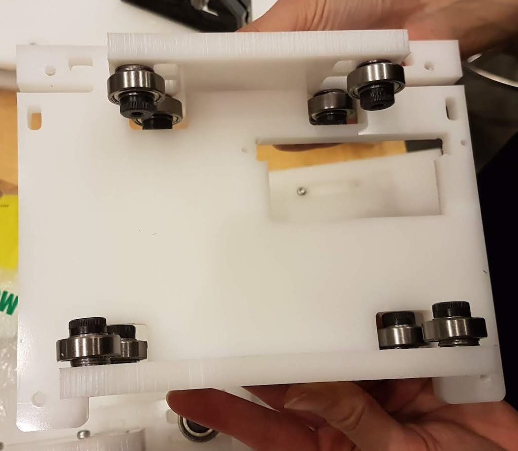
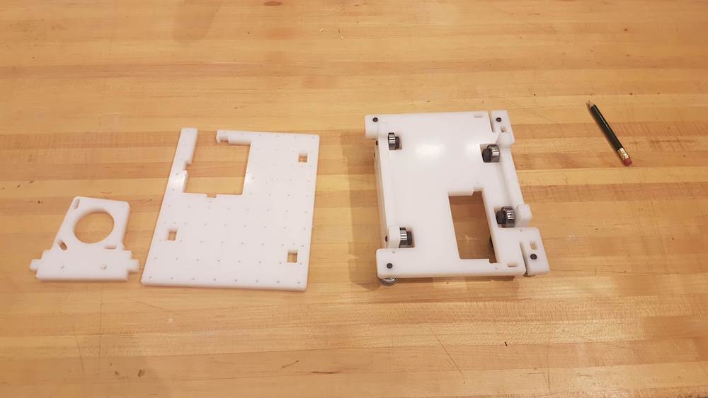
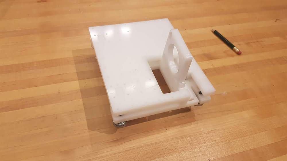
Step 13: Summary of how to press fit the complete gantry guide system together and secure them with screws.
Step 14: press fit the motor mount plate with the already screwed in ball bearing to the gantry system. Now you should have a sliding guide.
By the time you get here, you should have the following:
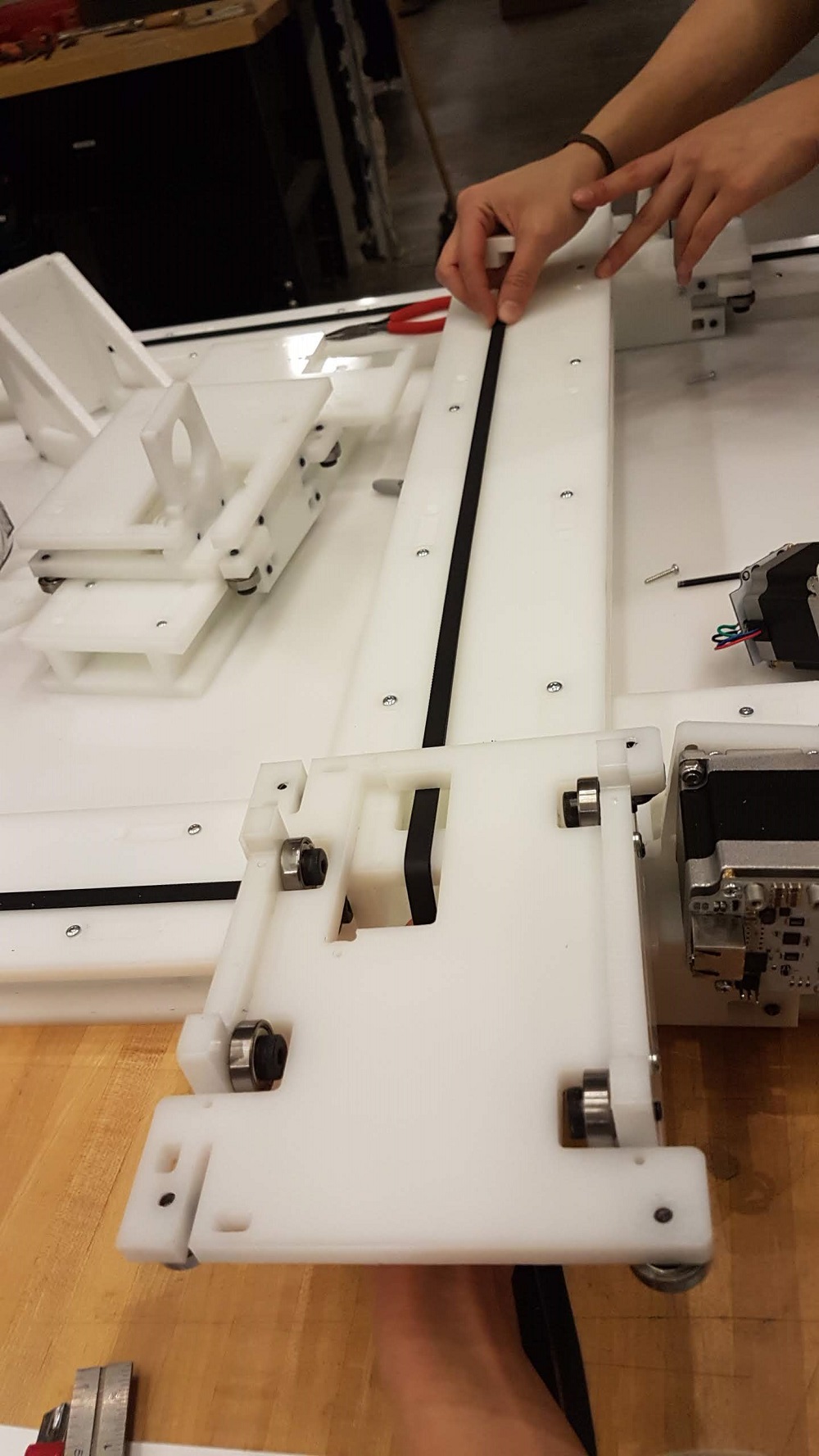
Belt Installation for Guide (Rail) System
Installing the belt is a very tedious process. You need to make sure you do them one step after the other, otherwise you will find yourself taking things apart once again like we did endlessly.
Step 15: for your belt length: measure the length of your axis and add an extra foot length for the pulley on the motor. You will need two belts per axis (one of them will just be the length of the axis plus a few inches more for extra
adjustment.
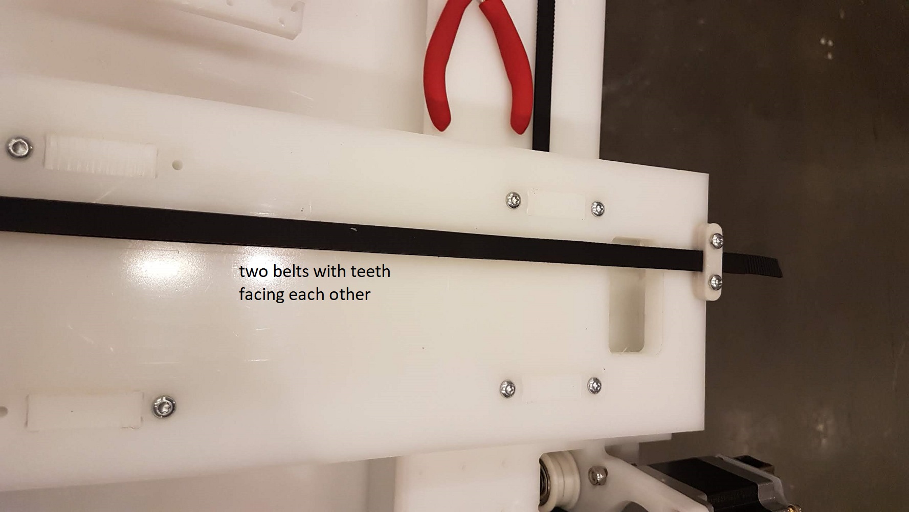
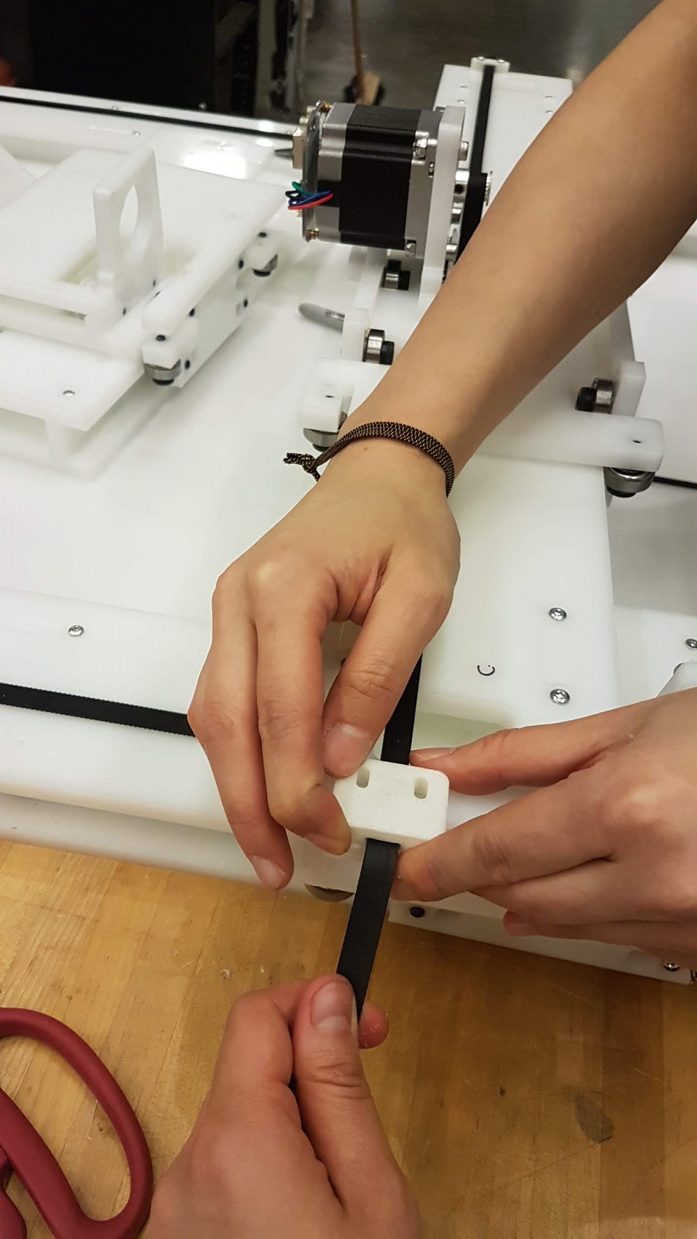
Step 16: The two belts teeth are facing inward against each other. Attach one side first using the 3D printed part as seen in the picture below.
Step 17: Hold the belt tight to make sure the teeth are aligned. Slide the guide system into the rail. See picture below.
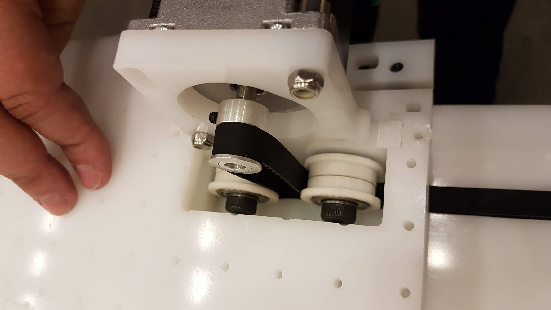
Step 18: Put in the pulley component on the shaft of the motor. Place the motor on the motor mount plate and place attach the belt into the pulley as the picture below.
Step 19: Pass the belts through the other 3D printed part as seen in the picture below. Screw and tighten it.
Step 20: After it is tighten, place the 3D printed to create a 90 degree angle, this will secure the belt in place. See picture below.
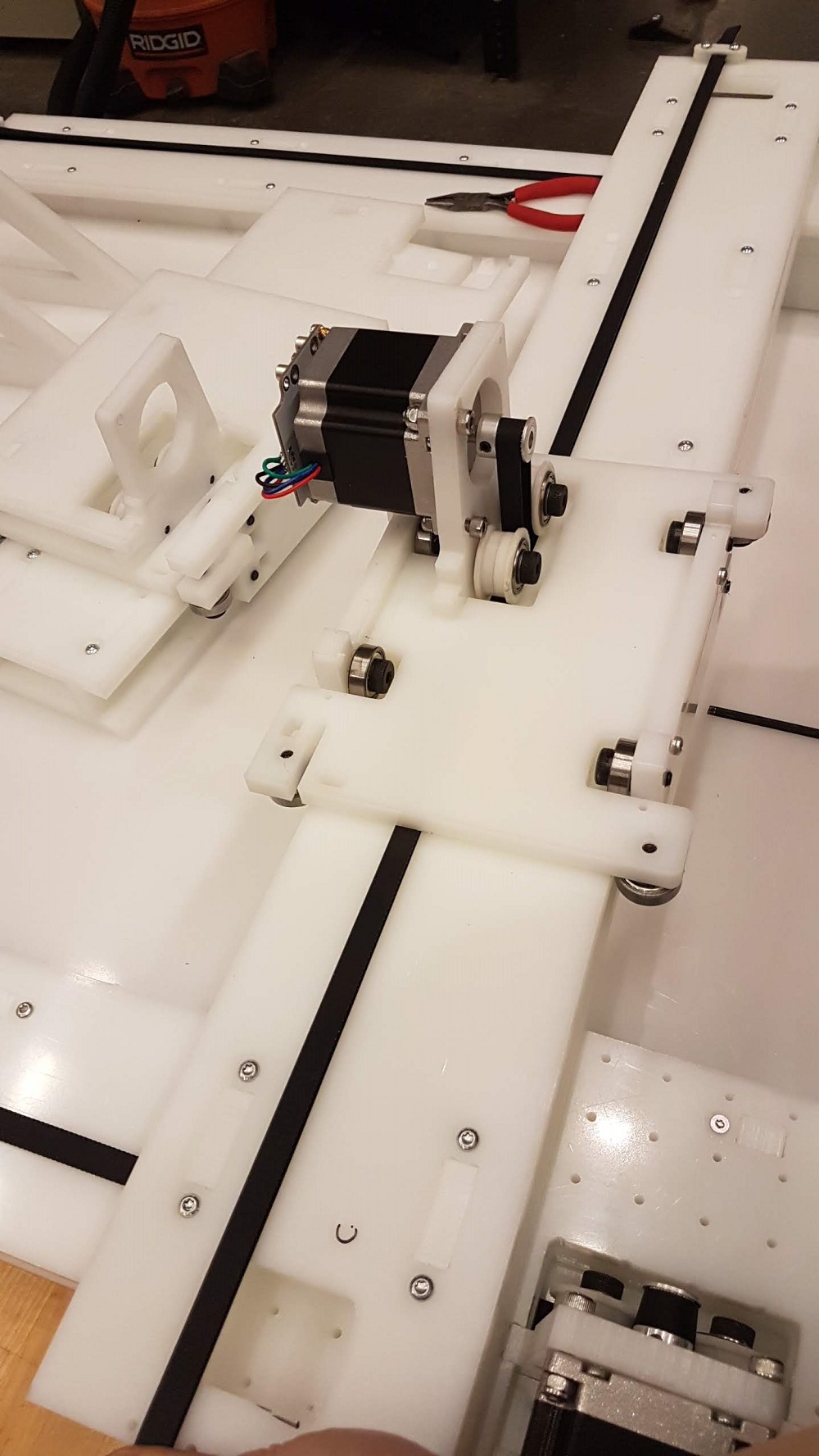
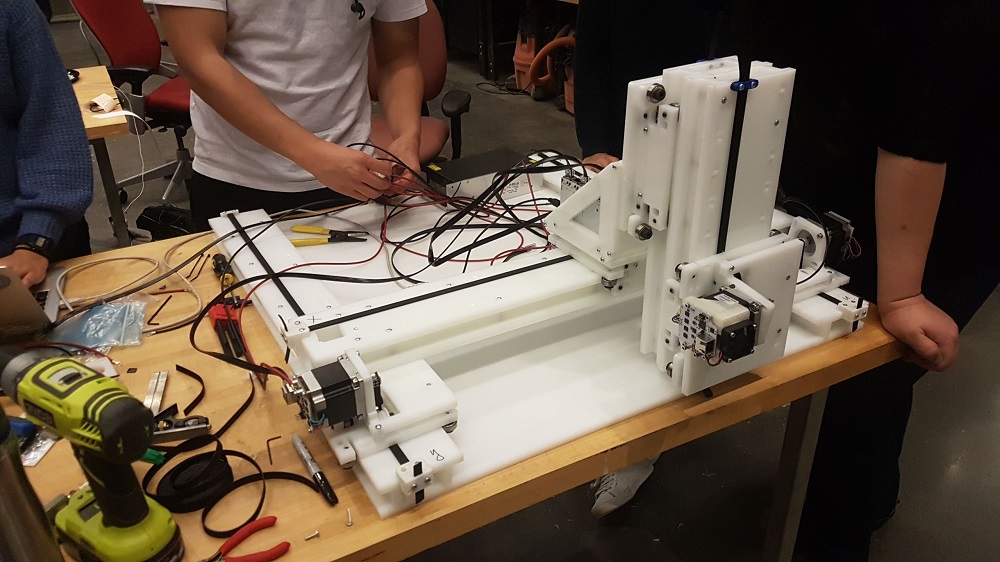
Once you are done installing the belt on each axis, you will have something like this:
Z-axis and End-effector Attachment
The Z-axis assembly is the same as the other axes. We have to make an extra component to attach the Z on top of the X-axis.
Step 21: Put together the attachment as seen below. (You should pretty much figure out how to based on the plates).
Step 22: Screw the above component on the X-axis guide (Rail) system. See picture below:
Step 23: Screw the Z-axis guide (rail) system on the component above. See picture below.
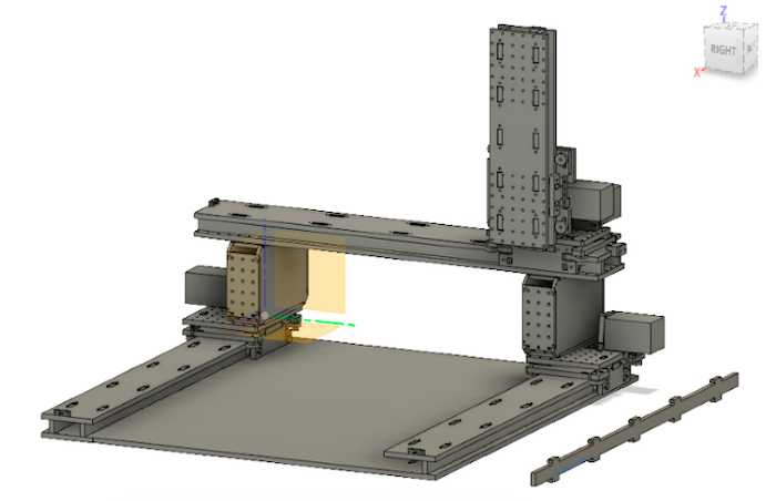
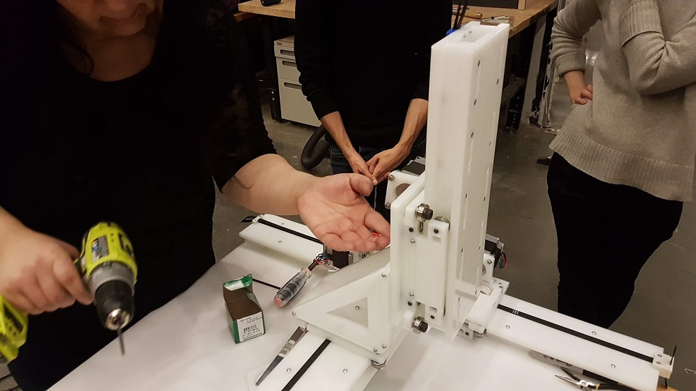
Wala, now you can attach your own end-effectors. Here is a picture of our machine while assembling the electronic on it. Notice that our end-effector is actually another Z-axis look-alike. We might not be able to use it because of the weight.
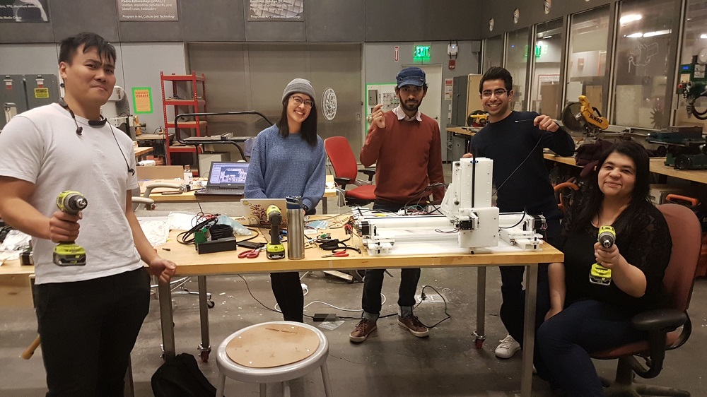
It was past midnight. T-13hr before class demo day. Everybody still smiling!
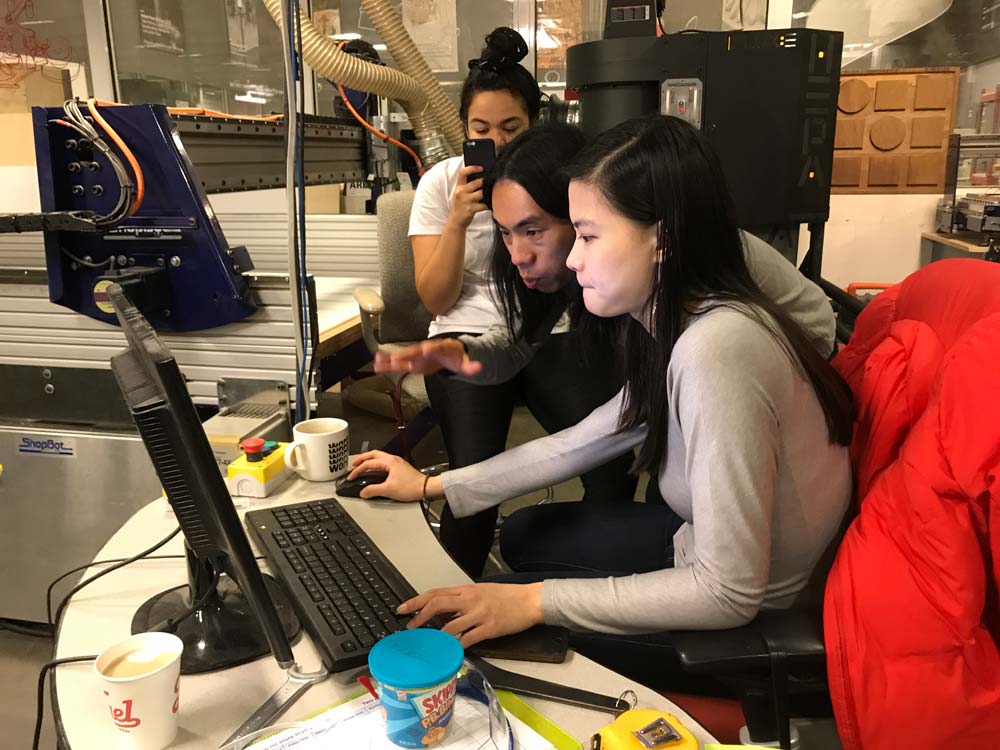
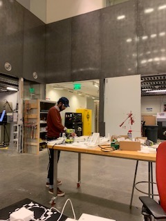
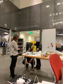
People at work...
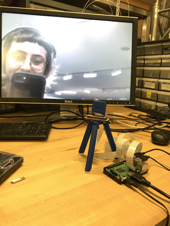
CAMERA
The idea was to have a mini-tripod/photobooth to capture faces and spaces before they were happily extruded into chocolate replicas. This was accomplished with the help of Nancy on the design/encasing side and Océane on the
programming/installment side. The photobooth will snap a photo and upload it to a Dropbox folder, where we can convert it into .svg -> gcode formats.
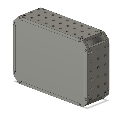
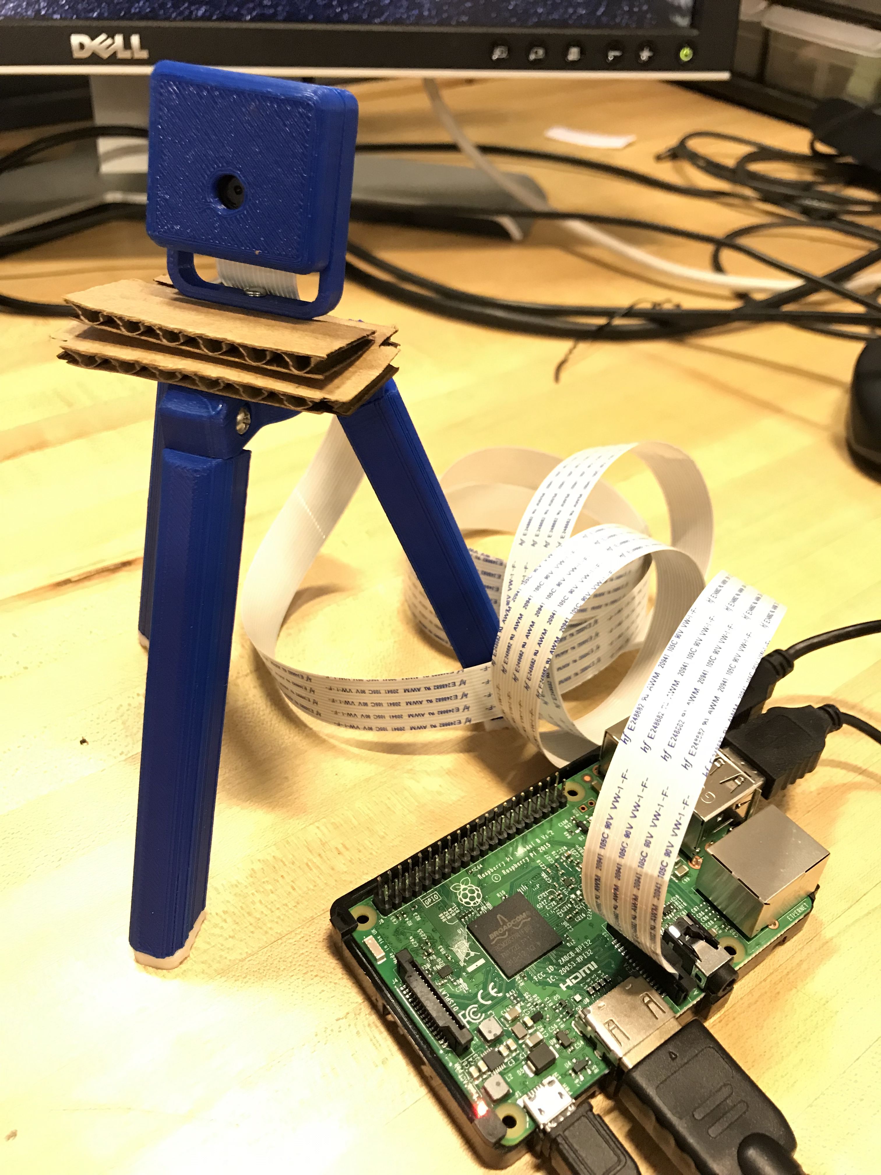
CASE DESIGN/PRINT
inspired by AdaFruit's vintage camera on a tripod look, we printed out the .stl files on the 3D printers in the CBA shop
We printed out the tripod legs, grippy feet and base connector. For assembly, we used 4x #2-56 machine screw, 1x M3 machine screw, 3x #4-40 3/8 machine screw + nuts.
PROGRAMMING
There are SO many ways to do this online, so I was inspired by many sources, namely this, which allowed me to take what was needed to integrate (proper libraries) and figure
out the Dropbox app configuration. Let's walk through what that looked like step-by-step. Quick note, I will be programming this RPi3 headlessly, so in case the reader isn't sure what that looks like, I invite you to take a peek at this tutorial to see how one can SSH into an RPi and program it remotely.
RPI CAMERA
Picamera has excellent documentation on how to use the library! Upon inserting the camera string (the camera we're using is the V2-8
1080p).
In order to get the RPi3 up and running with the latest and greatest, there were quite a few package downloads that needed to be completed frrom the RPi terminal, so I'll try to consolidate them here:
            #note:  python 2 or 3 should work here. if using python2,  just replace "python3" with python
            sudo apt-get update
            sudo apt-get install python3-imaging
            sudo apt-get install python3-gdata
            sudo apt-get install python3-imaging-tk
            sudo apt-get install python3-picamera
            sudo apt-get dropbox

           #and last but not least,  don't  forget to enable  your camera!
            raspi-config
I wrote up a quick script to verify that the camera was working
            #testing camera function
            #!/usr/bin/env python


            from picamera import PiCamera
            from time import sleep

            camera = PiCamera()
            camera.start_preview()
            sleep(5)
            camera.capture('/tmp/picture.jpg')
            camera.stop_preview()
Success!
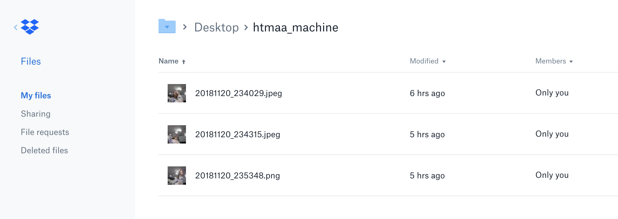
UPLOADING TO DROPBOX
Ready for uploading. I used the python for dropbox library. Everyone can access the pictures taken by the camera in the Dropbox folder here!.
If you fork the repo, don't forget to go to Dropbox developers and create an app in order to get an Access Token for Oath flow. Happy snapping!
PNG -> SVG -> GCODE
Since our plotter only takes gcode, we perform a seperate conversion using ImageMagik and Inkscape to convert between file types. Some resources found to help with this was a online gcode
simulator, svg2gcode library
EXTRUDER
To design the chocolate extruder we begun by doing research on the best types of chocolate we could use as well as the ideal temperature for it to melt.
After looking at some previous projects that have also done a chocolate extruder, we realized there was quite a lot of divergent information.
Most of the webpages were recommending to use dark chocolate, with a high percentage of cacao and with out palm oil. The temperature in the syringe, recommended to melt the chocolate, was between 31-33 degrees celcius.
These are some of the websites we have looked at:
After this initial research, we started the design of the chocolate extruder.
Since Filippos Tourlomousis had already worked on the development of the concept of the extruder itself, we already had a good idea of how the design would be.
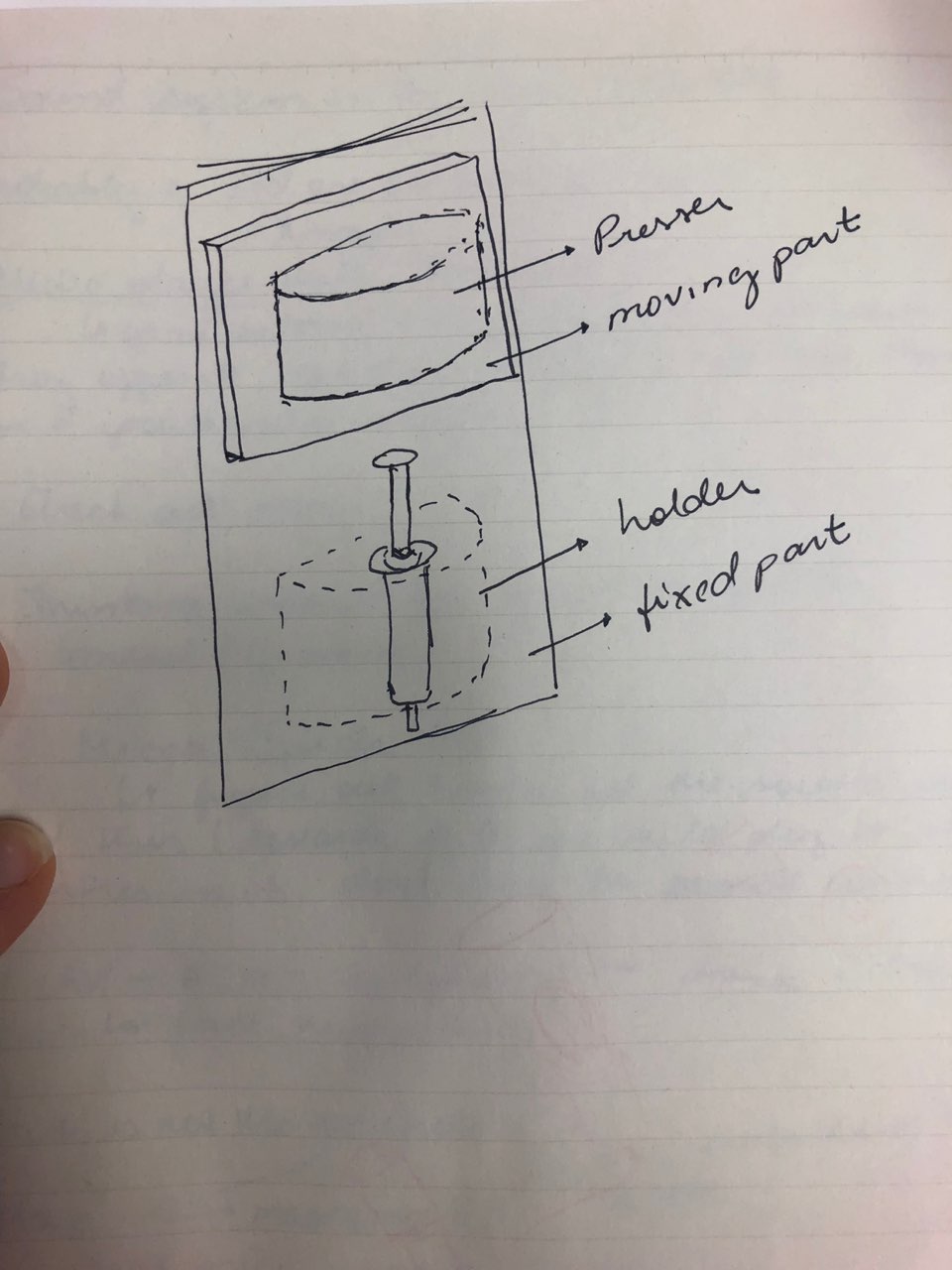
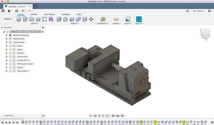
We needed a syringe, with a heating system around it to keep the chocolate melted, as well as a holding body to embrace the syringe and a pressing body to press the plunger.
This system would be attached to a vertical axis, the syringe would be permanently fixed, inside the holding body, and the pressing part is the one which would move up and down to press the plunger.
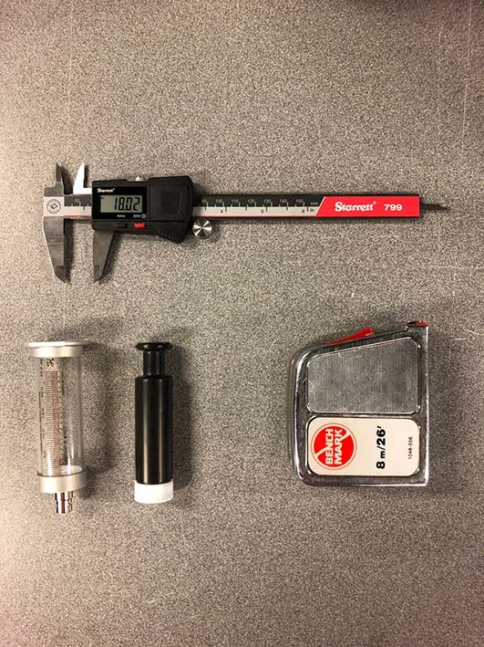
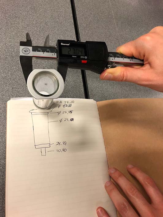
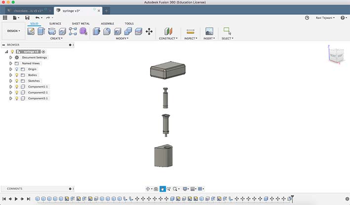
After that, we have measured the actual syringe using a pachometer and modelled it in fusion 360. We did that in order to be able to model the parts around the syringe with the precise measure.
This parts have been later on modified by Filippos Tourlomousis in order to better suit the strengh and pressure needs of the extruder. Filippos has also designed the axis where this parts would be attached to.
The syringe holder and the syringe presser have been 3d printed and the remaining parts of the axis have been milled in HDPE.