How To Make (almost) Anything
week 3 - electronics production
Learning to make an in-circuit programmer within a week
Wednesday
Received an overview of PCBs and how they are fabricated during a lecture.
Thursday
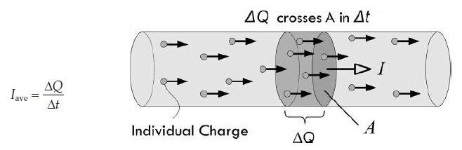
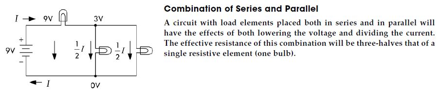
Learned about the basic physics and concepts of electronics, from the definitions of current and Ohm’s Law, to analyzing circuits.
Friday
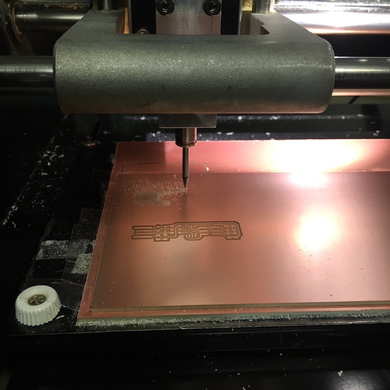
A brave teaching assistant demonstrated how to use the Modela MDX-20 3D Milling Machine to mill copper boards, as well as solder the PCB’s components to the milled board.
Saturday - Fabrication
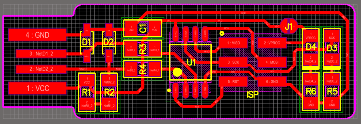
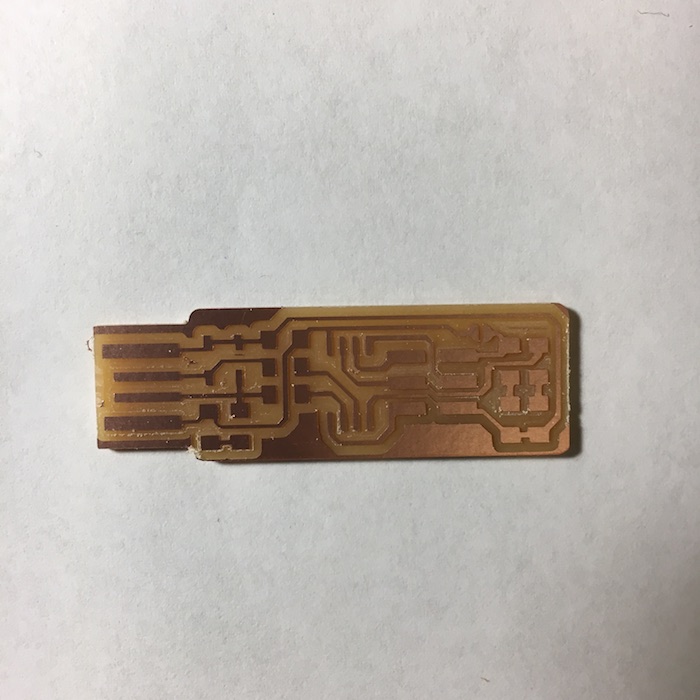
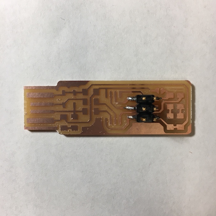
We were given 2 PNG files: 1 for the board’s traces and 1 for the board’s outline. We used the MODs software (created by Professor Neil Gershenfeld) to cut our boards with the milling machine, as described by the PNG files.
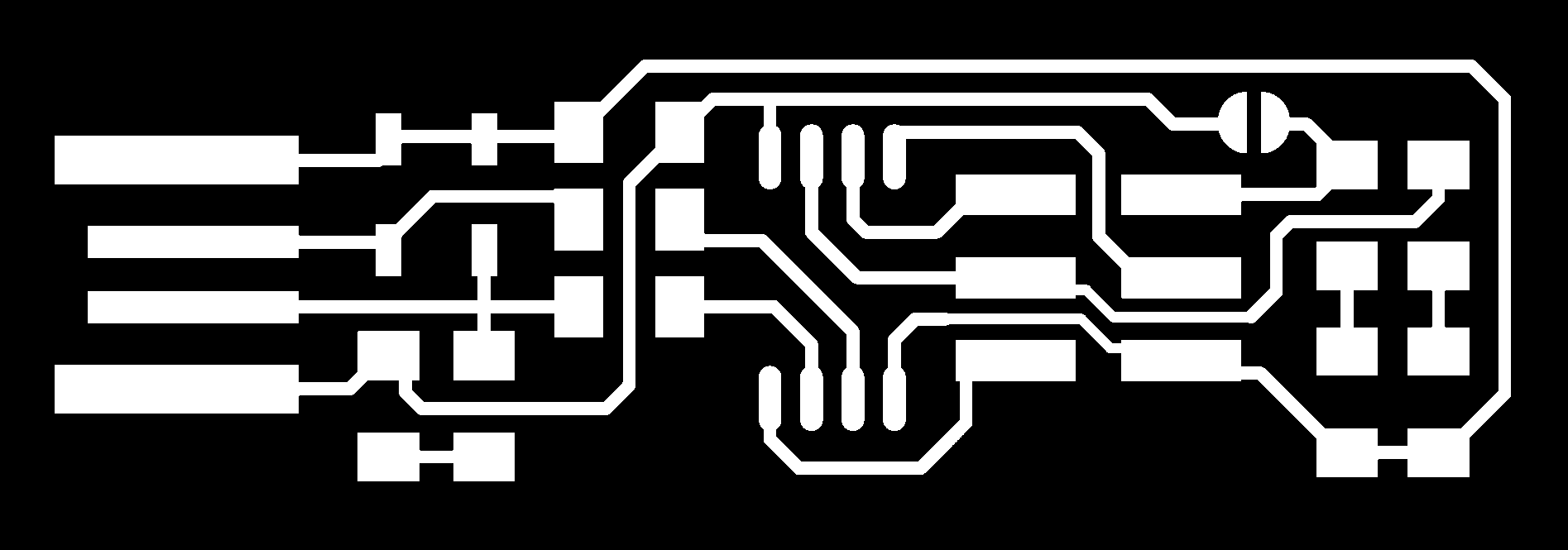

Traces: A depth of .24, and an offset of 3 was used to configure the machine for the traces. The MODs software then produced a new file, with 3 parallel paths (corresponding to the offset of 3) drawn for each perimeter in the outlines of the traces file. It was this file that the milling machine then used to mill.
Outline: A depth of .24, a maximum depth of .72, and an offset of 1, was used to configure the machine for the outline. The resulting file produced by MODs told the machine to cut the outline in 3 passes, to increasingly greater depths that started with 0.24 and ended with .72. The resulting cuts went all the way through the copper so that the milled board could be pulled out.
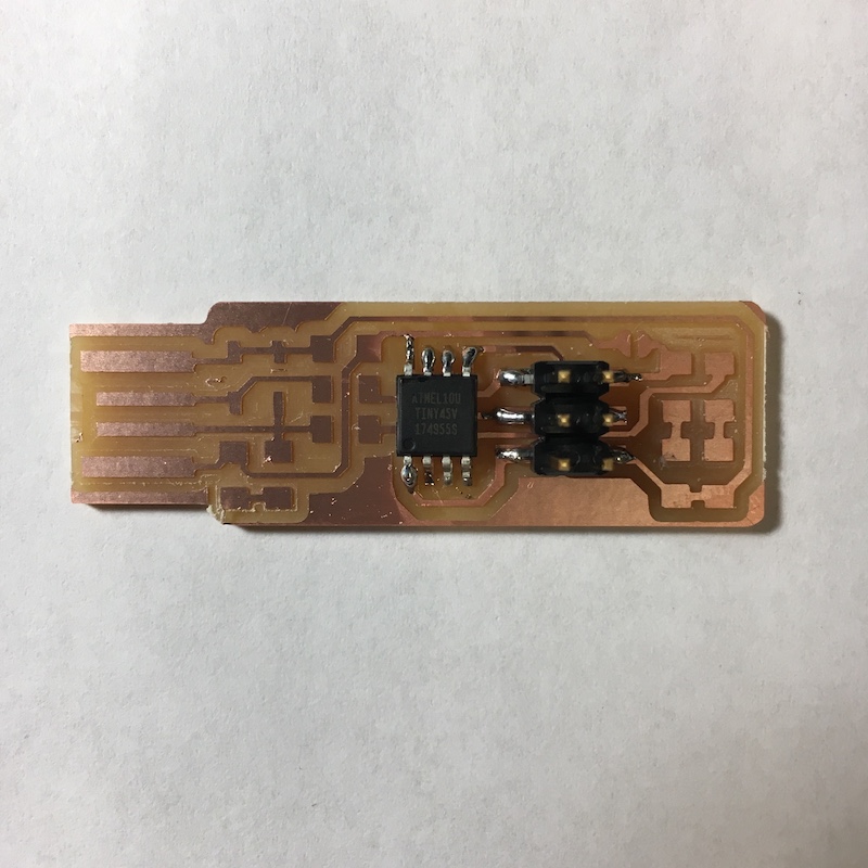
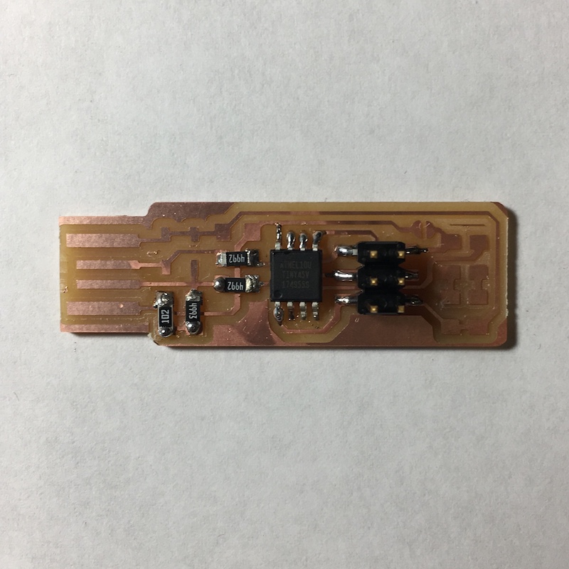
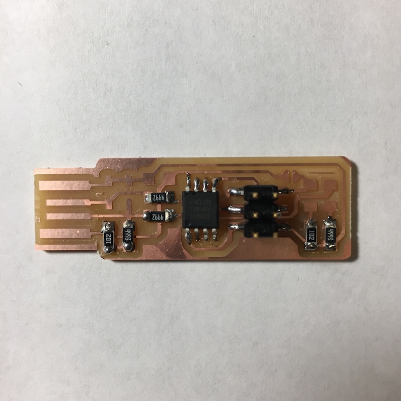
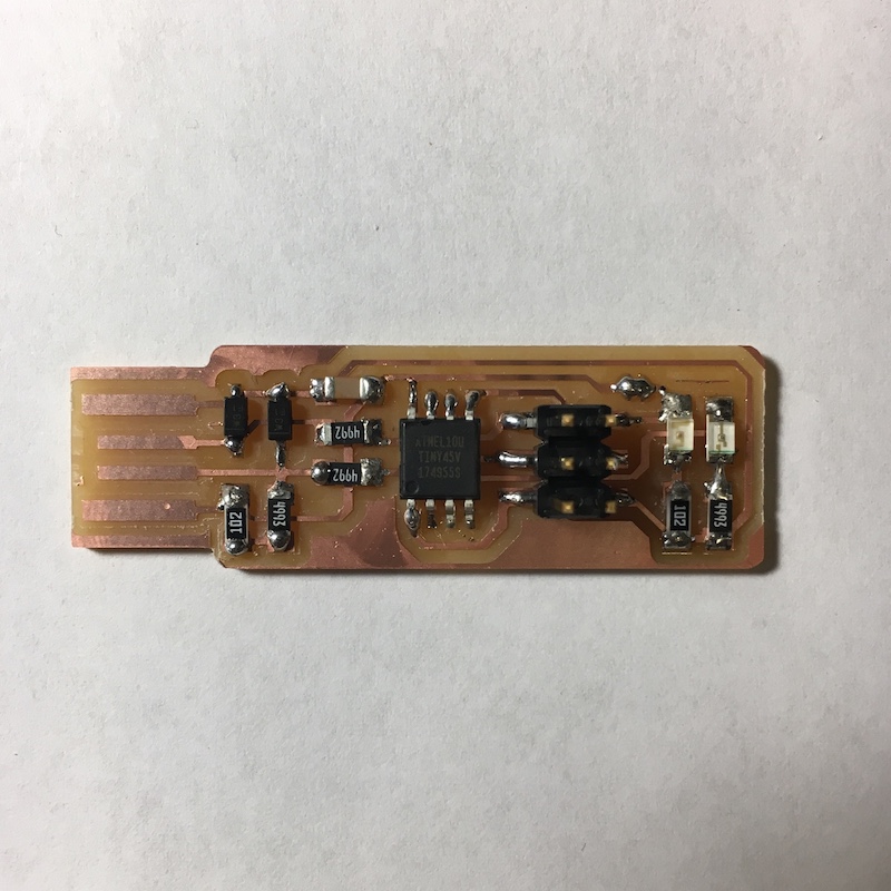
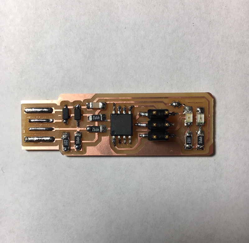
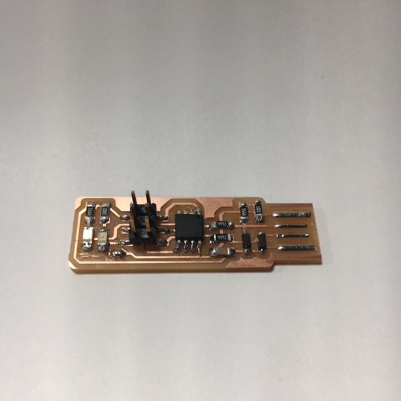
Instructions and schematic diagrams were used to figure out the locations and orientations of components to be soldered on to the board.
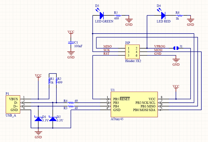
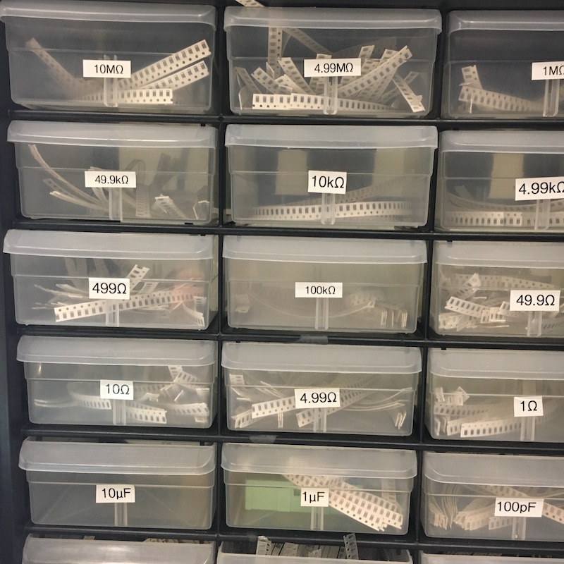
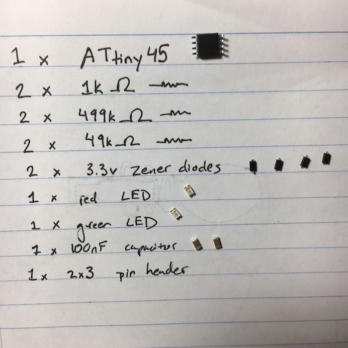
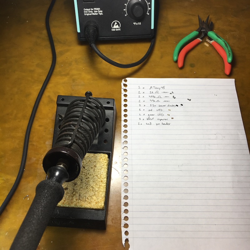
We selected and organized the necessary components, and soldered with tweezers under a magnifying glass.
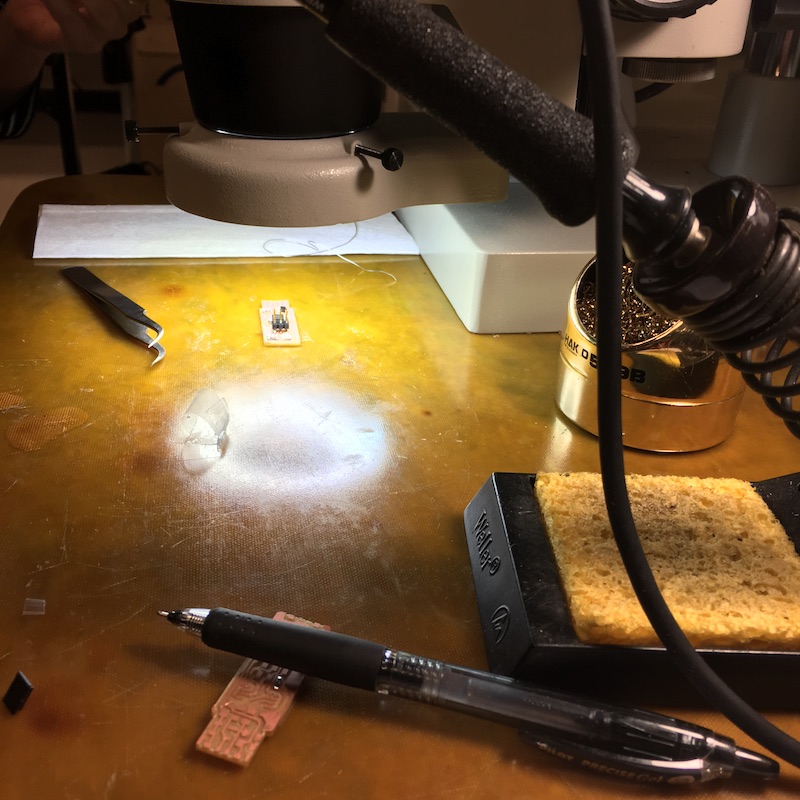
Soldering is a skill that Neil (the professor) calls "subtle". The joints I soldered are amateur rather than the desired “shiny and smooth” aesthetic.
Later...
Programming the board: The next step was to transform the board into a programmer that could then program other boards.
I followed the instructions on the page of a previous student, named Brian (http://fab.cba.mit.edu/classes/863.16/doc/projects/ftsmin/index.html), to program my board from my Mac book air. I was able to compile and run all of the code his page linked to.
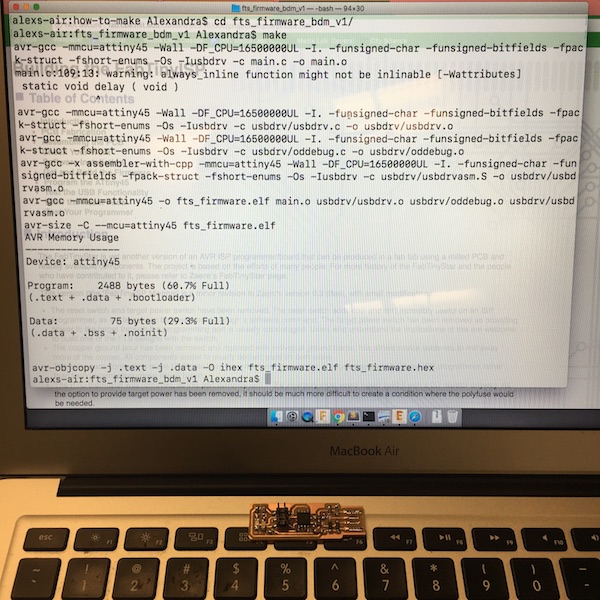
However, I didn’t know how to program my board, or have a board from which to program it. Tomás (a TA) pointed me towards a small translucent blue programmer (avrisp2) that I could use, so I updated the Makefile from the firmware source code on Brian’s page to use avrisp2.
I plugged in my board to the programmer and the programmer to my computer, but nothing happened... The LED did not light up. Luckily a classmate Elena was in the room and pointed out that my board wasn’t lighting up because it needed more power. Extra power was supplied by connecting a USB connector to the USB header of my programmer, and to my computer, and the LED then lit up as expected.
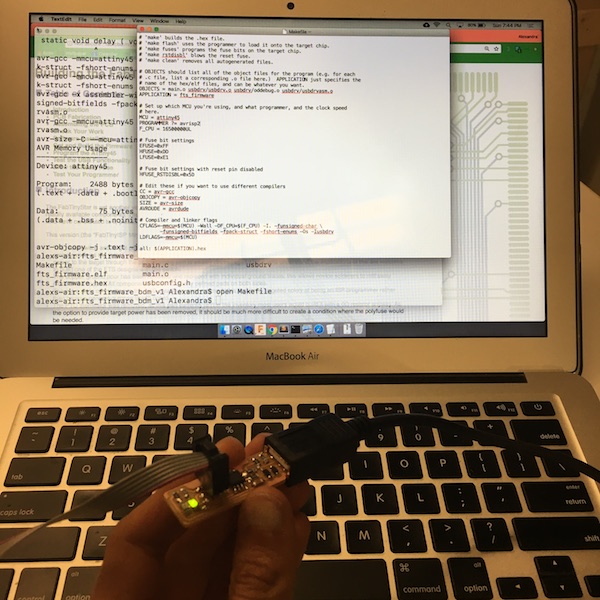
I was able to run the commands that were meant to load the code on to the device without any errors, but I could not get my computer to recognize the device and show it listed as a USB under its list of connected hardwares!
I tried getting other computers to recognize my device as well: I tried using my classmate Elena’s ubuntu VM, as well as the Linux machine in the lab. Neither machine recognized the device. There is probably a hardware issue with my board.