How To Make (almost) Anything
5 - electronics design
Task:
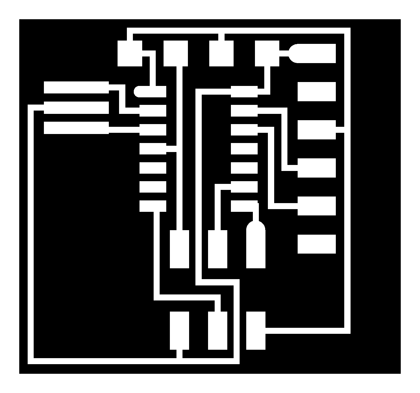
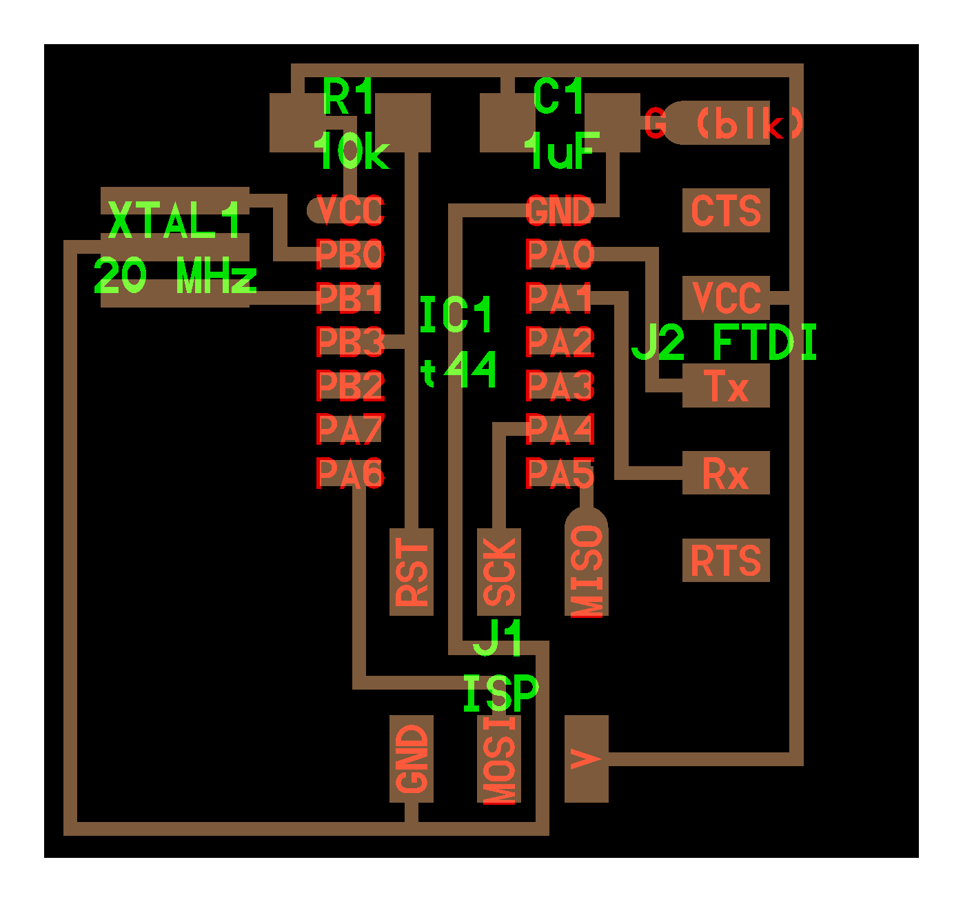
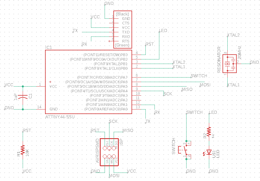
- Redraw the board (schematic and board diagram) corresponding to the diagrams/photos given
- Add a button and LED (with a current-limiting resistor) to the board
- Make the board (mill & solder the parts)
- Load code on to the board and test

Also given:
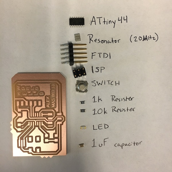
- Library of schematic parts
- Inventory of components we could expect to find in a fab lab
- Link to code for testing the board
- A photo showing how someone ran the code
The task felt like a cryptic message, given that I barely knew how to read board schematics or what the components on the board may be, or how they work.
Backing Up
I decided to use Eagle as the EDA software to create my board.
I watched a collection of Eagle video tutorials.
I read a series of sparkfun tutorials, starting with the most basic:
- What is Electricity?
- What is a Circuit?
- PCB basics
- How to read a schematic
- Using Eagle: Schematic
- Using Eagle: Board Layout
- I stared at many schematics from last year’s “How to make (almost) anything” class
Making
- Board design: 7+ hrs
- Milling: 3+ hrs
- Soldering: 3 hrs
- Testing: 1 hr
Drawing
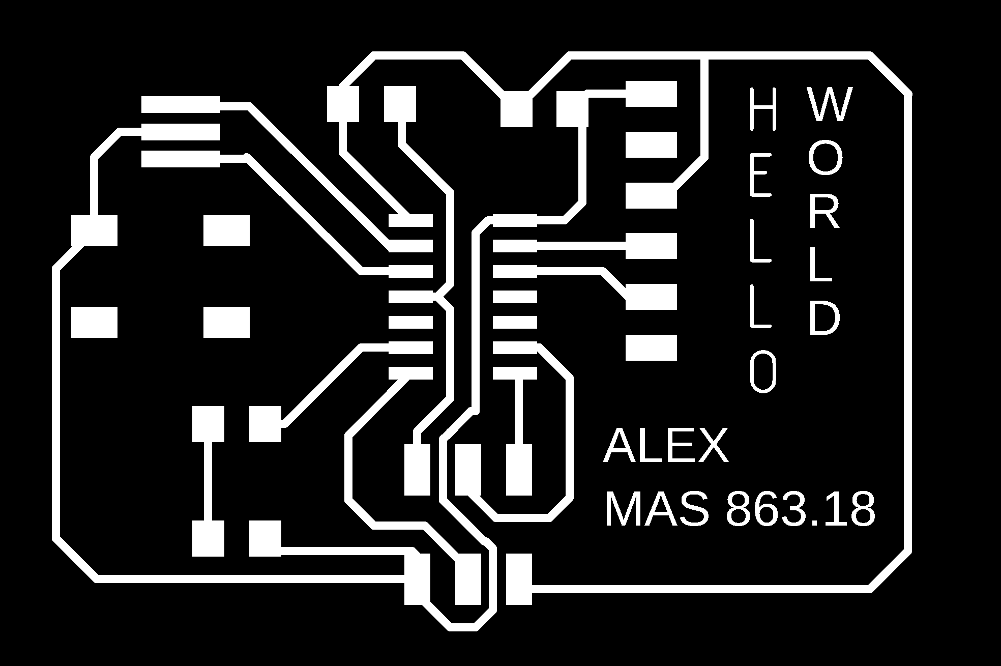
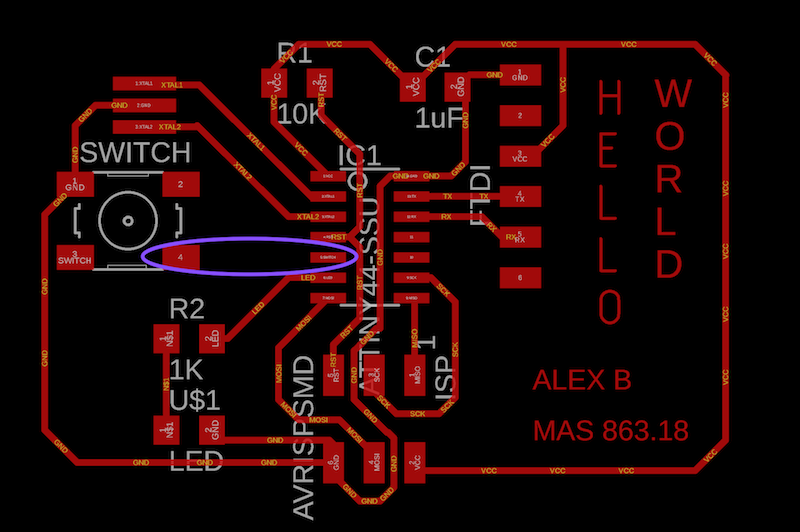
I created my schematic and board with Eagle.
Routing the traces for the board so that no routes overlapped was a challenging problem, and I failed my first try. For my second try, I reconfigured the connections in the schematic so that I could lay out the board in the same fashion as the example provided, with the new components connected to adjacent pins and occupying negative space that had been left in the example board.
Eagle errors: I had trouble removing airwires that I couldn’t see and eventually decided that they did not matter, as long as the traces were properly routed.
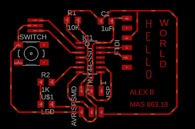
In the outline of the board, I added ridges alongside the resistors. These ridges are meant to mimic the resistor symbol in circuits and serve as reminders of where the resistors are on the board. The detail is a nod to how I have learned about circuits in the past week.
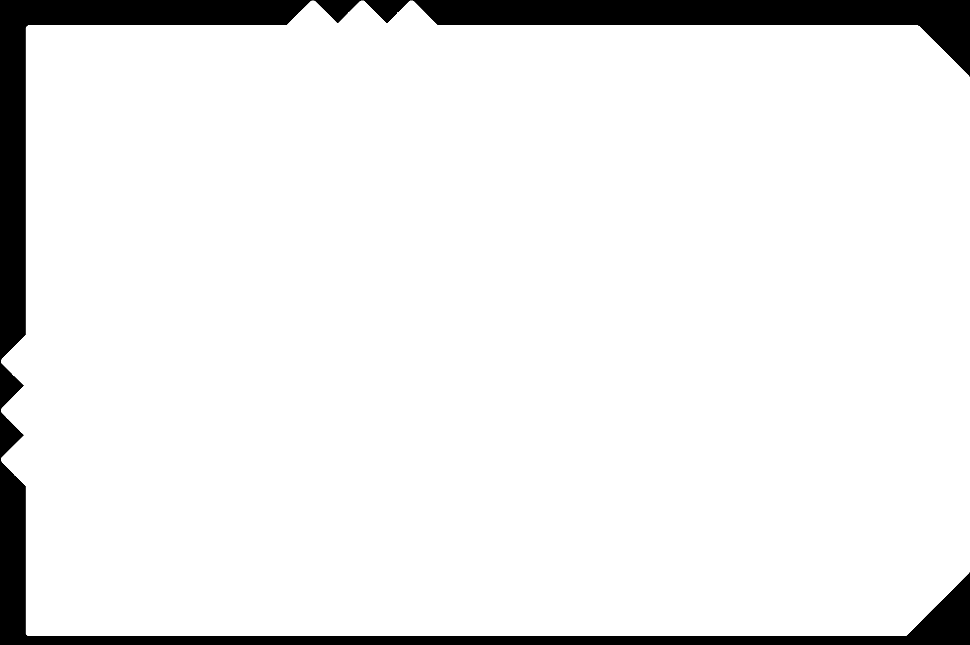
I exported my board as 2 PNG files: a file for the traces, and a file for the outline. To export the images, I used the eagle commandline.
disp none top→export imagedisp none dim→export image
Milling
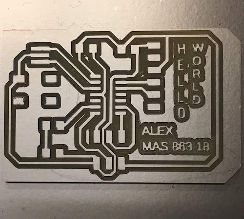
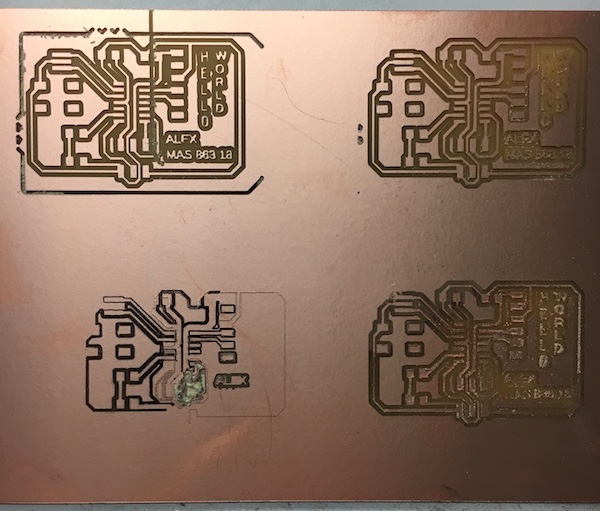
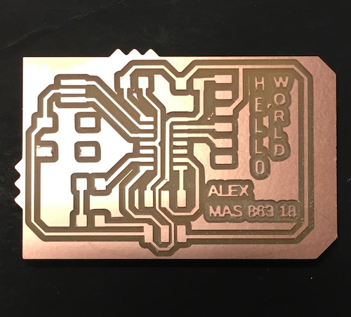
I milled the board with the MODs software and the Roland Modela MDX-20 milling machine, which took a few hours, with multiple failures.
- The endmill broke
- The outline did not cut (to fix, I had to use the GIMP image editor to add margins to the PNGs I had exported from Eagle)
- The traces did not mill evenly
After milling, I realized there was an error in my board design: I had somehow deleted the trace routing the button to the microcontroller! By the time I realized this, the milling machine was occupied. I decided I would try to fix this by adding a DIY jumper wire at the time of soldering, because that’s a thing, right?
Soldering
I selected and layed out the parts to solder to the board
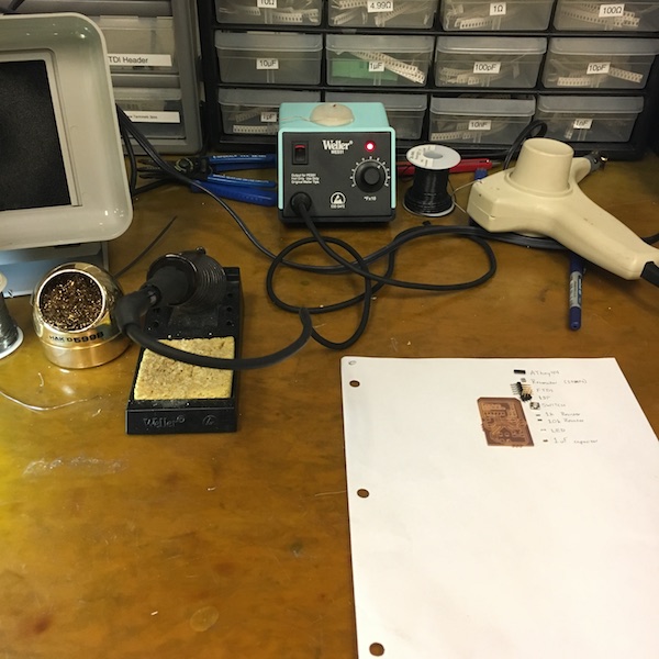
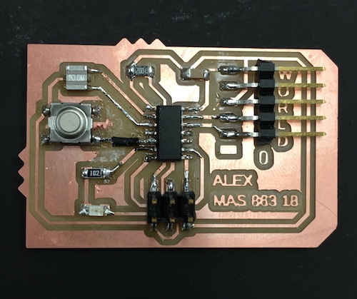
And soldered the components, working my way from largest and most interior, to smallest or outermost, as had been recommended.
I attempted to add a DIY jumper with a thick soldering wire I found to make up for the missing trace. I cut out the copper below where the jumper would go so to avoid a short circuit. The result was messy.
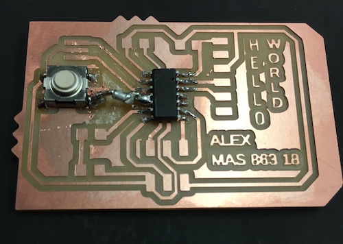
Afterwards I asked Tomás (a TA) about the likelihood of the jumper working. He recommended that I instead cut a piece of insulated wire to use as the jumper. Thank you for the hardware wisdom, Tomás.
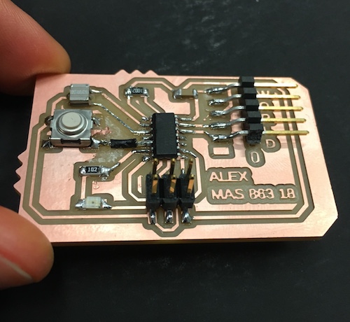
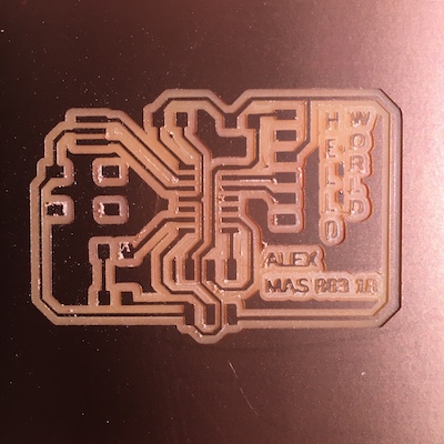
When I completed soldering, I realized that the FTDI header hid the “HELLO WORLD” detail I had added. Another design failure.
Testing
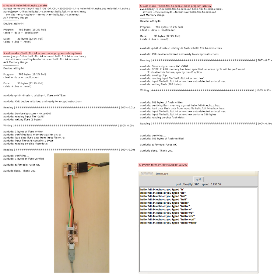
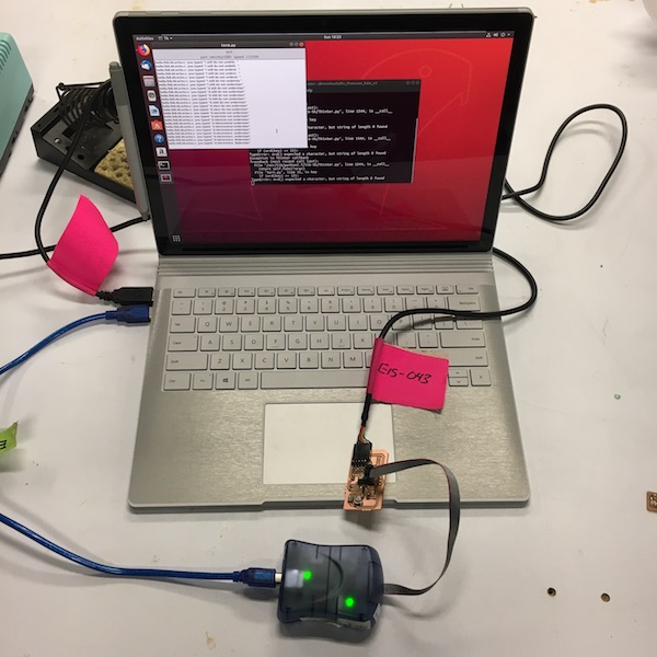
Code was linked to on the class website to use for testing the board. There were no instructions accompanying the code, only an image of how someone might attach their board to wires and type mysterious commands into their terminal.
I copied each of the files to my local machine. I found the term.py file linked elsewhere on the class site. I connected my board to my machine with the avrisp2 that I found in the lab. I was limited to using the avrisp2 as the programmer because I had not successfully programmed a board from the electronics production week. Because of this, I used separate commands I found in the Makefile that allowed for using an avrisp2 rather than the expected usbtiny.
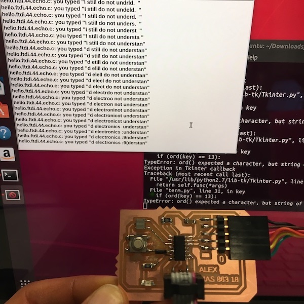
I successfully compiled the code and ran the commands.
However, one of one of the mysterious commands from the image was python term.py /dev/ttyUSB0 115200 and unfortunately my mac computer did not have a file named /dev/ttyUSB0. Luckily my classmate Elena was using an Ubuntu VM which did have such a file, so we used her computer for the rest of the testing.
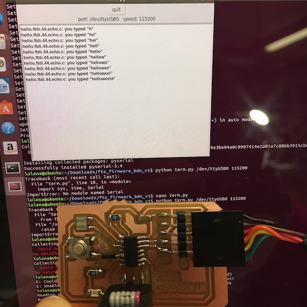
Success! Hello World. I almost understand electronics.