How To Make (almost) Anything
6 - computer-controlled machining
Task: MAKE SOMETHING BIG
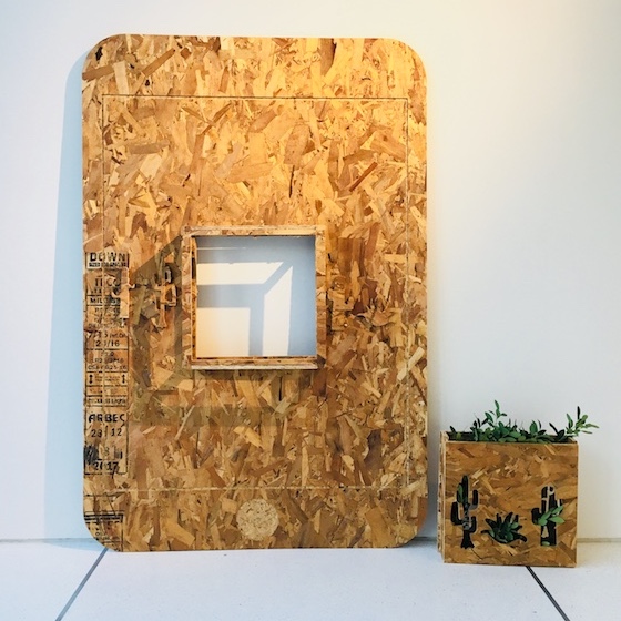
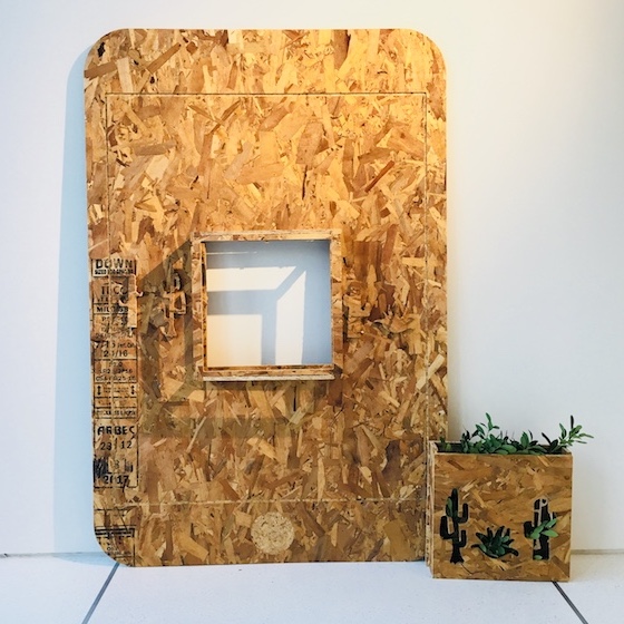
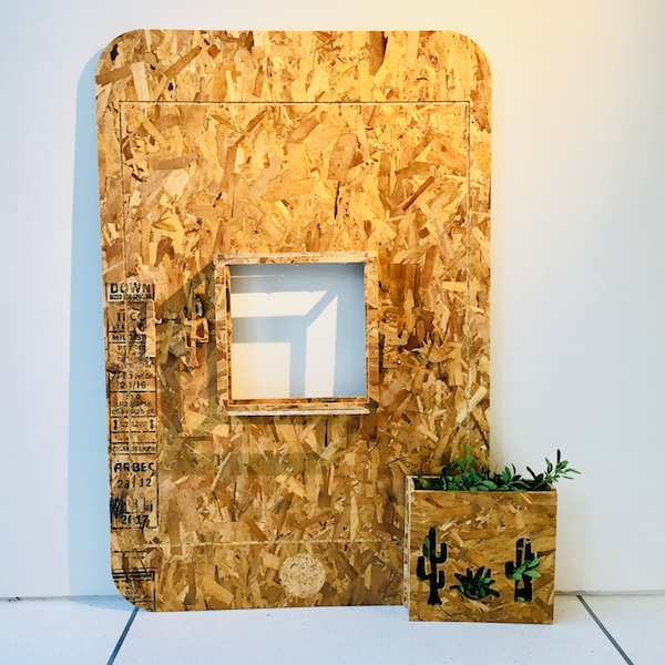
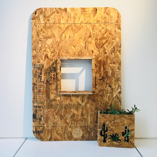
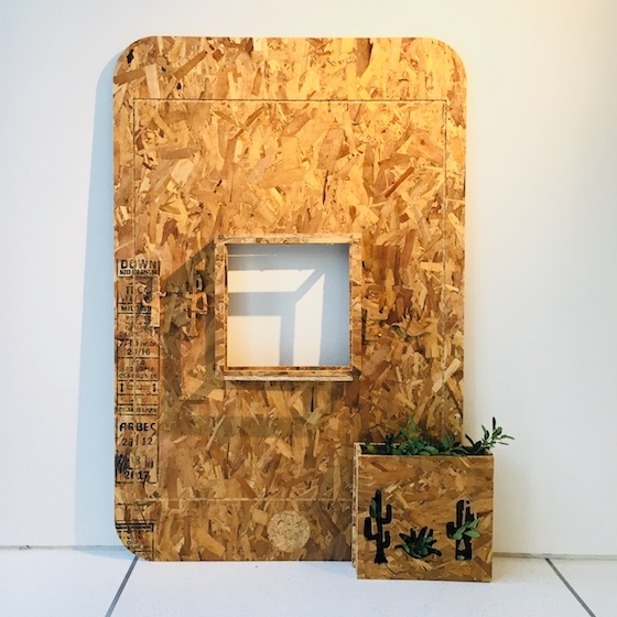
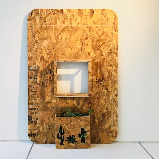
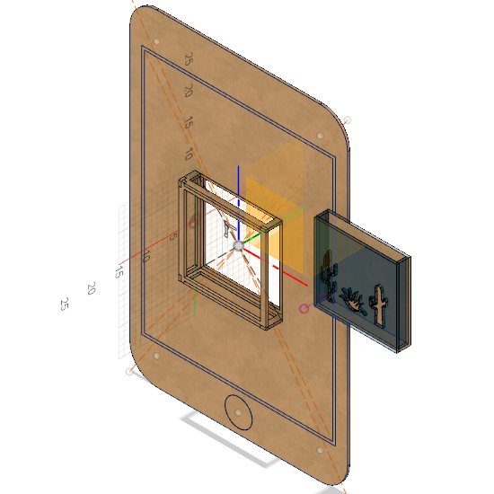
I took this opportunity to model “AR enhanced wall plants”, which I will create in the coming weeks as a final project.
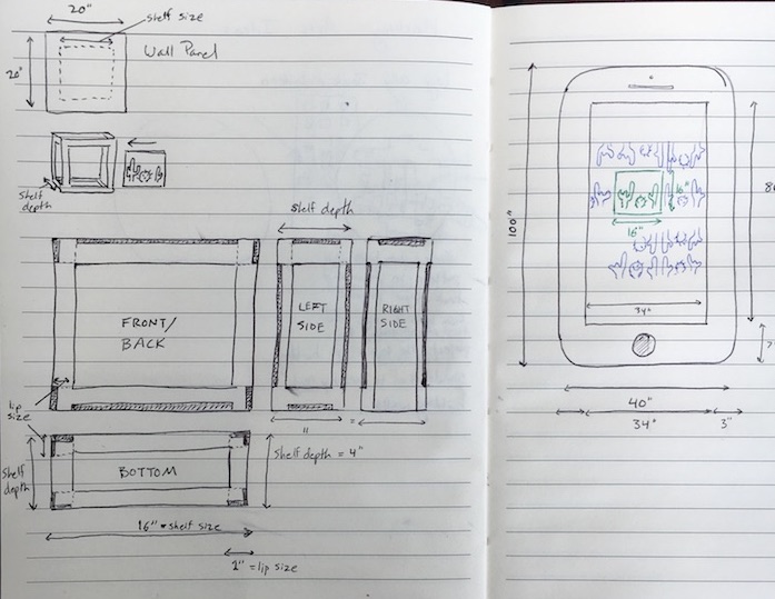
Design parts:
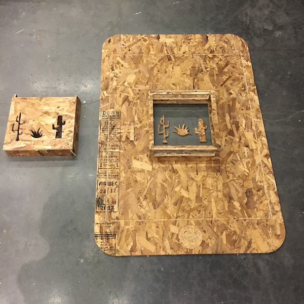
- Transparent box for plants
- Wall shelf for box to slide into
- Phone/Wall exterior to hold shelf, while demonstrating the intended AR experience realized with a phone desert landscape when viewed through the AR lens
AR (augmented reality) experience: There is small square wall shelf holding plants. This square mirrors and extends itself and it’s plants into an expanding desert landscape when viewed through the AR lens.
Process: CAM
Material: OSB (oriented strand board a.k.a cheap plywood)
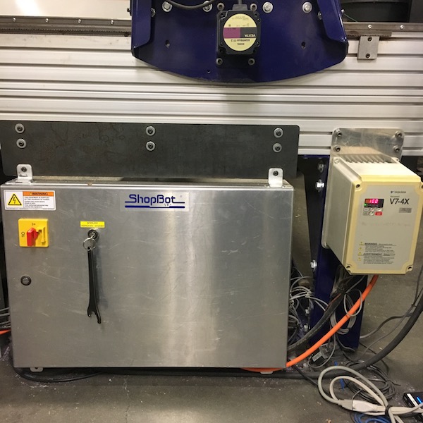
Machinery: ShopBot Full Size PRSalpha CNC
Workflow
I was new to the process of CAM; it took me a bit to understand the intended workflow:
1. Design / CAD: Model design in CAD software.
Export design as .dxf files.
2. Toolpath: Transform design from CAD to a path for the CNC machine to cut along.
Import design .dxf files. Create toolpath for CNC machine. Export as .sbp file.
3. Cutting: Transform toolpath into a format for the machine to understand (gcodes) and work the machine to cut the material.
Import .sbp file into shopbot software. Set up material and machinery and cut!
Making
1. Design / CAD
Using 3D modeling software is a helpful way to develop or better understand a design. However, only 2D line output is necessary for simple shopbot cutting. The 3D design is mostly a sanity check that the parts will fit together properly as designed.
Each face of the completed model is then exported as a separate .dxf file to then be recomposed in the toolpath software.
My making:
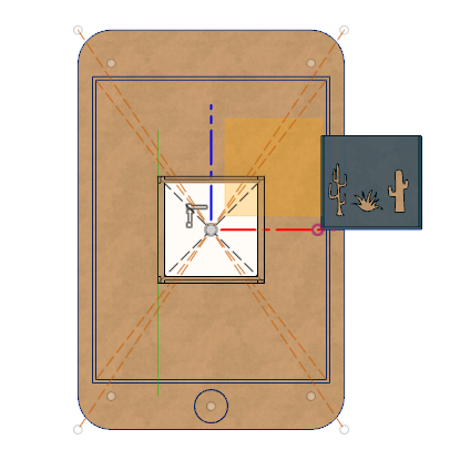
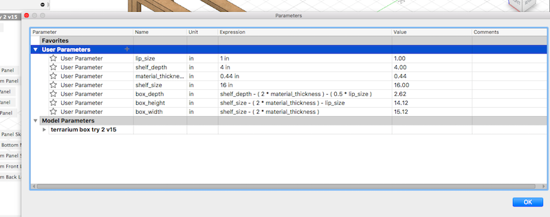
I used Fusion 360 to design and made use of parametric variables and constraints.
I first attempted to make the model without any guidance. I then watched a helpful YouTube video that walked through making a box with finger joints, and followed along for a second attempt at construction. This guided second attempt was much more successful. Video
Exporting the model’s faces was problematic. I transformed each into a sketch by using a projection, and then exported the sketches as .dxf files. This was a buggy process, and information was lost.
2. Toolpath
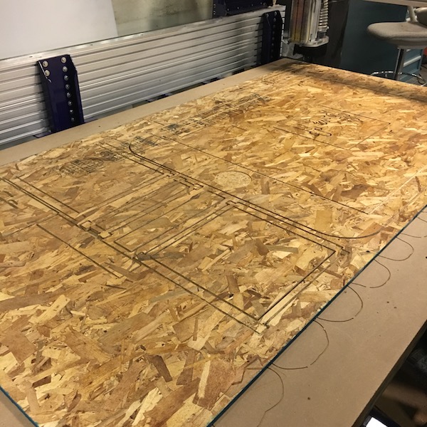
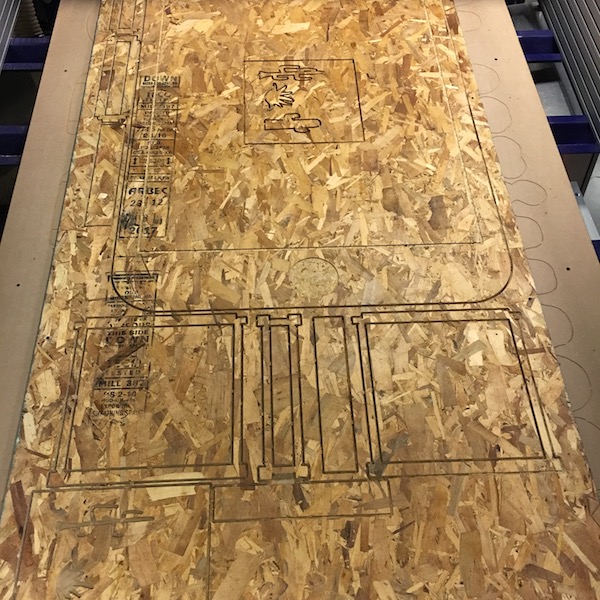
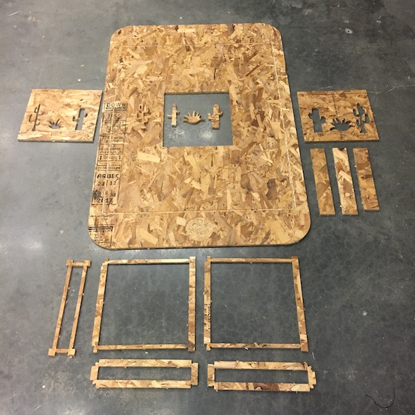
After importing the .dxf files into the toolpath software (vcarve), the designs must be arranged on the virtual material that will be cut. In our case this material was a 96”x48” OSB board.
All designs import as vectors. Any open vectors must be closed for the toolpath software to understand them.
Some vectors are transformed into pocket toolpath cuts, in order to etch designs. Other vectors are for “profile” cuts, which cut all the way through to cut out shapes.
The settings for toolpaths and configurations of tools with which they are cut, varies by material and the material thickness. All of these settings are configured within the toolpath software (vcarve).
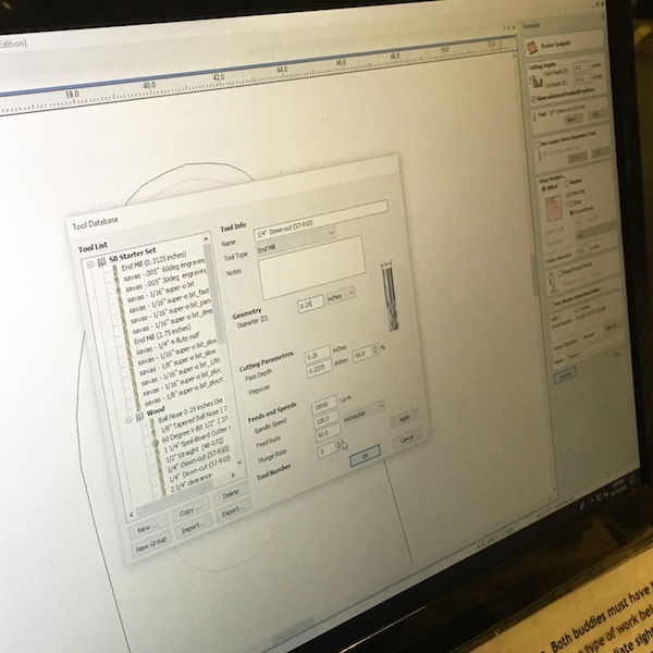
Since all shape paths are cut on one board, the order in which they are cut is important. Proper ordering keeps parts from moving as they are cut. Order of cutting: pocket paths, then profile paths, working from interior to exterior shapes. Inserting “tabs” into the design can also help prevent parts from moving as they are cut.
3. Cutting
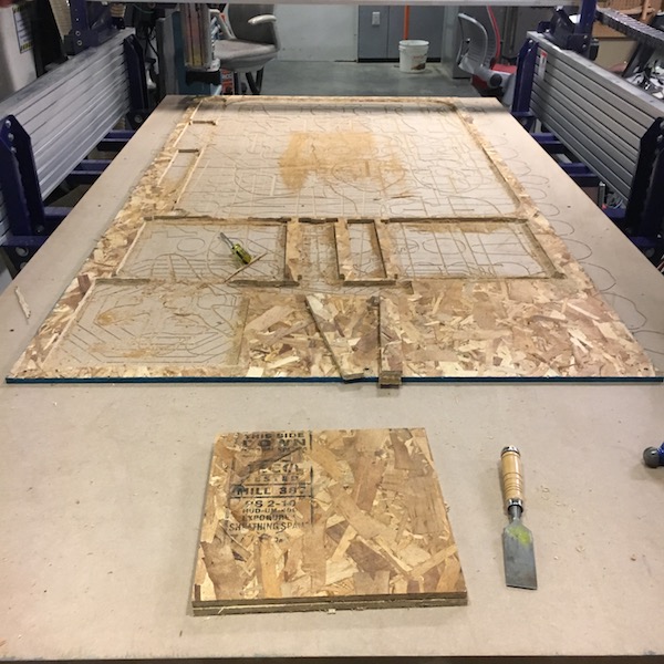
The material to be cut is screwed into a “sacrificial” layer of material that rests on the CNC machine (shopbot) bed.
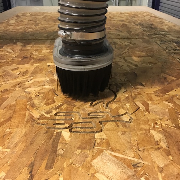
The machine is “zero’d” so that what the software interprets as the starting corner and depth at which to cut is true to the physical set up in real life.
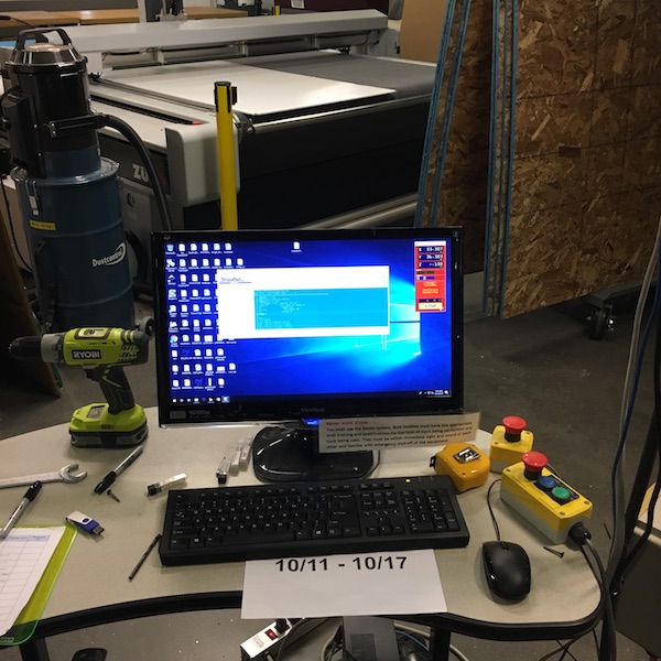
The .sbp file can then be loaded and the cutting can begin.
The machine is dangerous… Safety reminders:
- Always wear safety glasses near the machinery.
- Know how to turn the machinery off before you start it.
- Never work alone. Never leave the machine working itself alone.
- Never reach towards the machine while it is on.
Removing my pieces was difficult because I had added so many tabs!
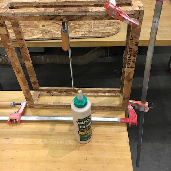
Assembly
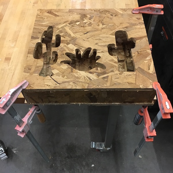
I used wood glue + clamps to bind the walls parts of the cactus box, as well as the panels of the shelf.
I used a drill + screws to attach the shelf to the phone wall.
End Failures:
- The cut size of the cactus box parts were not consistent when they came out of the shopbot. I had to measure and cut them again with a power saw.
- The cactus box was too wide to slide into the shelf.
- The shelf box size was larger than the square cut into the phone wall. This was a problem because the shelf was meant to perfectly fit into that square.