Week 0. CAD design FINAL PROJECT UDPATES
Hello World! We are live! After testing Jekyll on several computers, I finally have it working! No more troubleshooting this site (hopefully).
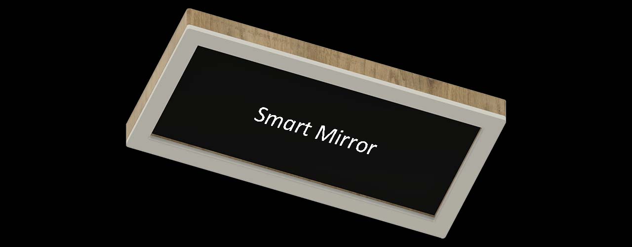
What if I finally make my Smart (Magic) Mirror?
Here we go, no more excuses. I am making a Smart Mirror, better known as “Magic Mirror” in the Open Source community. I have been wanting to work on this project for a few years now. It is time to make it happen!
What is a Smart (Magic) Mirror?
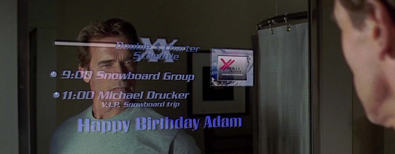
A Smart (Magic) Mirror is basically a mirror interface that shows you information about the date, the weather, your name, email, news, just about anything of your interest. But it does not stop there. It could be smart enough to response to your demands. It could act as a command center for your smart home as well if you incorporate enough sensing capabilities and AI in it since it has a brain of its own. It could be touchscreen, voice-controlled, gesture-controlled, anything you could think of~ The Sky is the Limit! ~ or your pocket.
2D Sketch of the Smart Mirror using Adobe Illustrator.
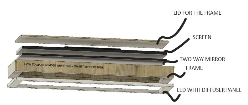
Smart Mirror Architecture
After trying out different CAD softwares, I chose Fusion 360 for 3D rendering the Smart Mirror.
My Smart Mirror will have several components in it. An LED diffuser panel with programmable RGB LED strip inside, a good durable frame, a two way mirror, a monitor, a Raspberry Pi with custom-made electronics, and finally the lid to hide everything inside so it does not look ugly.
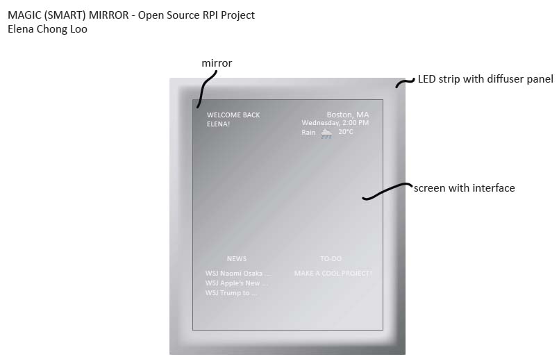
My Smart Mirror Goal
Since there are so many things I could create with this project, I will probably have to continue working on it after the semester ends. Here is the basic layout of my Smart Mirror with the following features:
- When someone is in front of it, it turns on the screen.
- LED loads around the frame at startup.
- Display basic information about the date, weather, news?, TO-DO, and name of the owner (me).
More advanced features that might be in the final project:
- Voice-control (Jasper, Alexa, etc…)
- Control LED Strip to display different colors, turn on/off
- Play desired music
- Turn on another smart device
- Gesture-control (Infrared, Camera, etc…)
- Display news based on hand gesture
- Touchscreen (it is expensive!)
- Face recognition technology
- be able to recognize me and say my name at startup
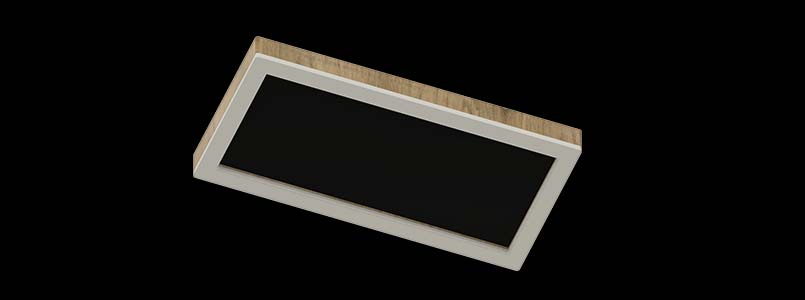
What my smart mirror would look like (hopefully).
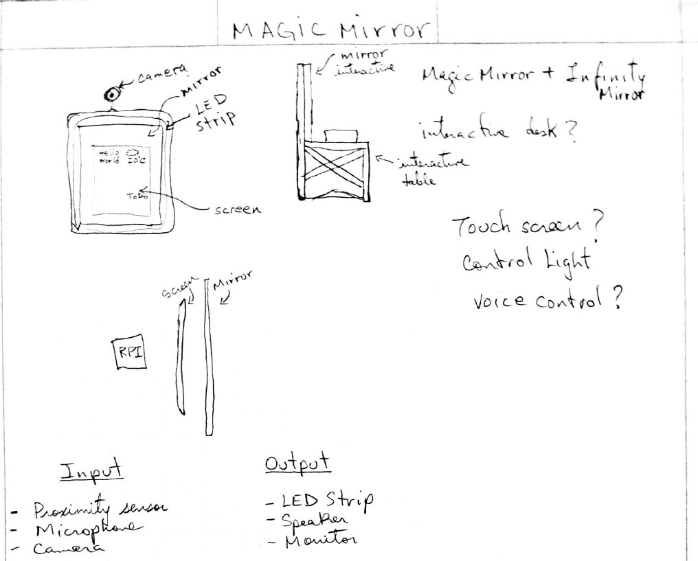
The early conception sketch. I can’t draw.
Video of the components in my Smart Mirror.
Final Project Goals
Collect Materials:
- Two way mirror
- Monitor
- Raspberry Pi
- Wood for frame
- Black fabric to hide light from back mirror
- ReSpeaker for Voice Assistant
- LED strip
- 2x Polycarbonate tube
- 2x Cotton fabric for diffising light (Thanks Sarah Sclarsic)
Objectives:
Frame
- Program raspberry pi
- Build website display for mirror
- Make wood frame
- Cut and assemble frame
- Paint frame and screen black
- Make attachment for holding monitor in place
- Add closing lid
Hardware and Software
- Smart mirror API setup
- Sound Reactive DotStar LED Strip Subsystem
- Test DotStar LED strip
- Design and fabricate circuit for LED output, and microphone.
Future Addition
- Tip/joke/quote of the day interaction Subsystem
- Tip/joke/quote of the day module shown on the mirror
- Read ADXL343 data from hand-gesture wearable device to change the tip/joke/quote
- Hand gesture wearable device
- Test ADXL343 accelerometer [failed, retry, success in 2nd attempt]
- Make and test resistive or capacitive sensors (optional)
- Test BC832 Bluetooth [RPI does not have bluetooth module, use WiFi]
- Test ESP8266 WiFi
- Setup communication between hand-gesture wearable and rpi
- Setup communication between hand-gesture wearable and sound reactive subsystem
- Test ReSpeaker for voice recognition
- Voice assistant to turn on/off lights
- Voice assistant for search
- Add camera for face recognition
- Face recognition and image overlay
October and November Updates
For the past few weeks, I have been gathering the material to work on my final project. I realized that I might need more than just building a smart mirror to meet the class requirements. So I have decided that in addition to the smart mirror, I will try to build an input/output device that could figure out finger pressure for additional interaction with the smart mirror.
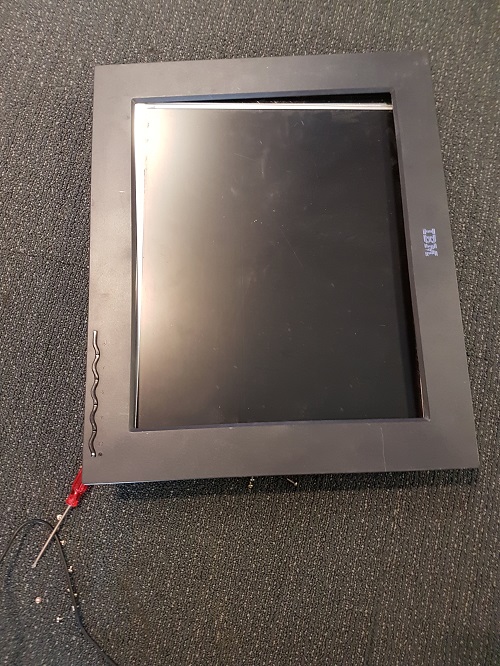
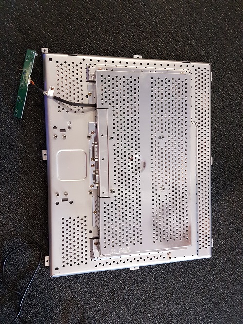
I have been checking the reuse room and slack since the beginning of week 1 for a used monitor for my project. One day, I finally found an old IBM monitor without its power adapter. Fortunately enough, my group keeps all kind of adapters and I was able to find the exact one to power this on. I tested it and it works!
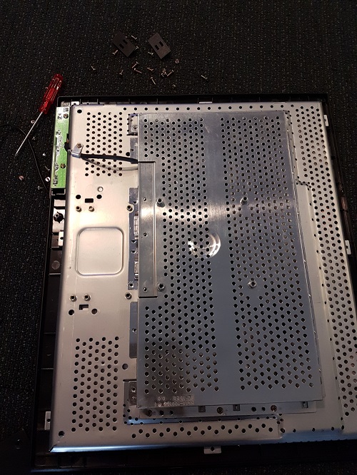
I took apart the enclosure to reduce the volume of the monitor down to fit inside the frame I am going to build.
I also found a bunch of two ways mirror in my lab from previous projects.
Update: November 14, 2018
Setup the raspberry pi 3b with the latest Raspbian OS. *Not the lite version because we need the GUI.
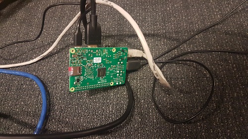
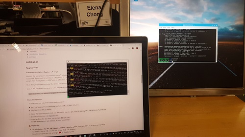
I followed the instruction on the Magic Mirror forum and used this tutorial. After I finished setting up the OS, I setup the rpi to work with SSH so I could directly program from my laptop. Then I installed the Magic Mirror 2.5V by running the following line of code:
bash -c "$(curl -sL https://raw.githubusercontent.com/MichMich/MagicMirror/master/installers/raspberry.sh)"
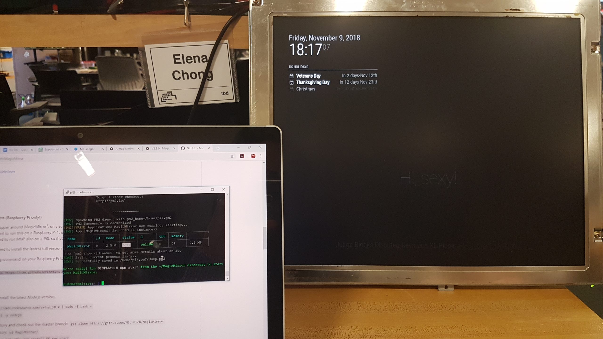
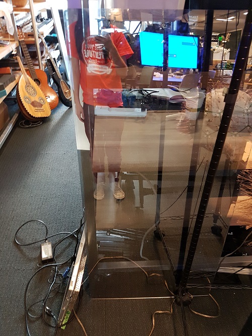
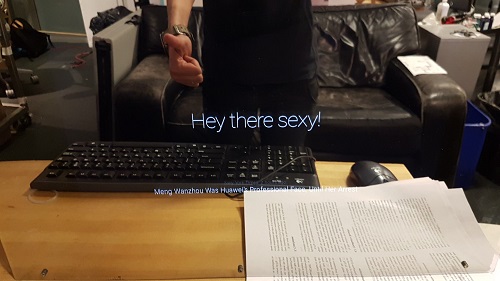
What the screen will display.
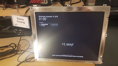
Once the mirror is in front of the monitor, the text displayed on the monitor will be visible.
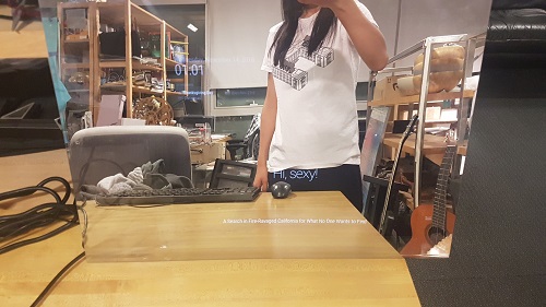
This is just a simple setup, I have not gotten to the actual programming and interaction part yet.
I also got the material for making the frame!
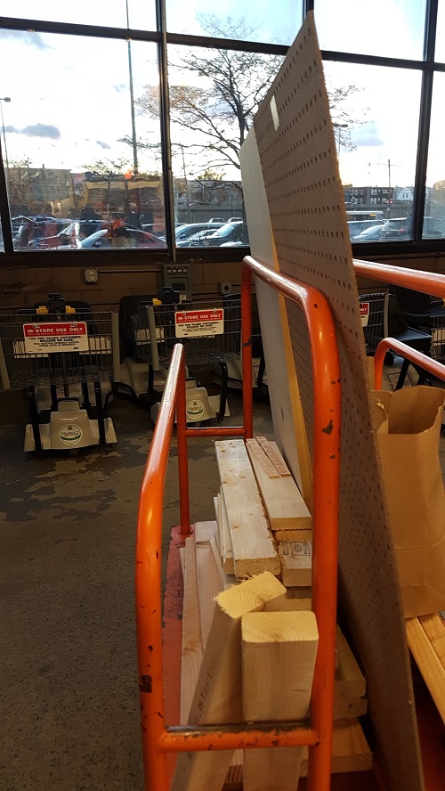
Wood for the frame.
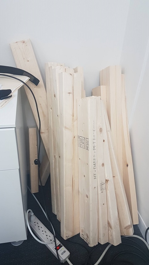
Time to work on building the frame! ~more update to come.
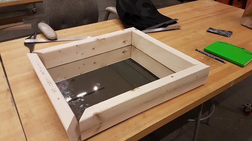
Update: First week of December!
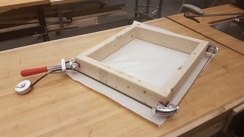
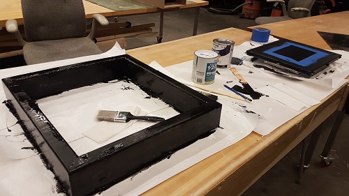
I finally made the frame. I cut the 2x4 wood to the size of the mirror, added a 45 degree corner for aesthetic, used glue for wood to paste the corners together and a special corner clamp to secure them while the glue dries.
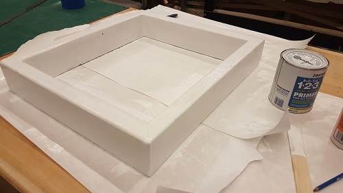
Once the glue is dried, I applied a couple of layers of white primer to cover up some of the imperfection of the 2x4. I had to wait 30 minute between each layer.
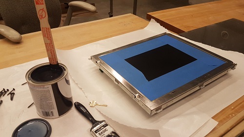
For the acrylic to clearly look like a mirror, we have to make sure that the side that the monitor screen is going to go, needs to be fully black except for the screen itself. So I taped the metal corner around the monitor with expensive painter tape and paint it with black paint.
After the white primer was dried, I applied a couple layers of black paint on the frame as well and waited for it to dry.
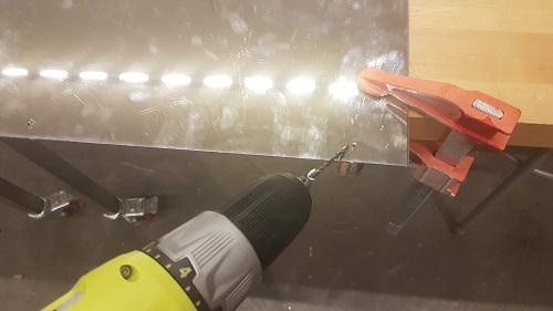
I drilled a couple of holes on the double sided reflective film acrylic to make it easier to screw in to the wood later.
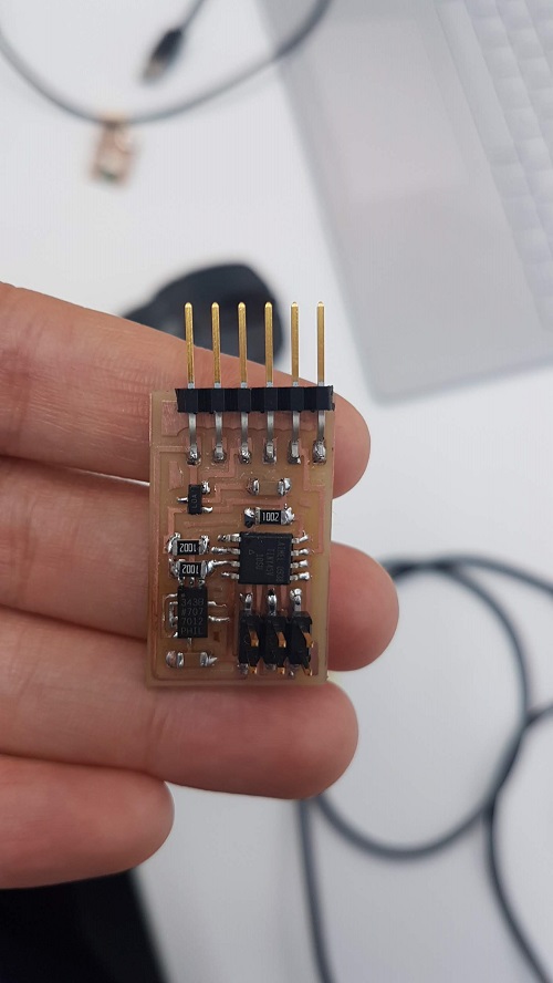
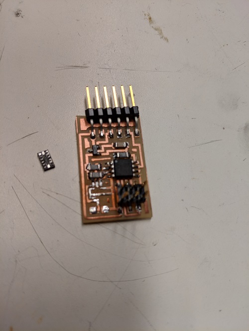
I also milled out the ADXL343 board from the input devices site and populated it. The ADXL343 itself is difficult to solder. I used the heatgun to solder it and discolored the FR1 board a bit. I might have to make a couple more for testing and improving my reflow technique. For the final project, I plan to use the accelerometer together with other resistive and capacitive sensors to create hand gestures for controlling output devices on the mirror side.
Update: Another first week of December
Last time, I stupidly painted the painter tape black and taped it around the frame of the monitor. Today, Sara Falcone reminded me that I can just use black vinyl… Not sure why it didnt come to me before.
So I cut strip of vinyl as well to seal the frame border to prevent light from going through the mirror.
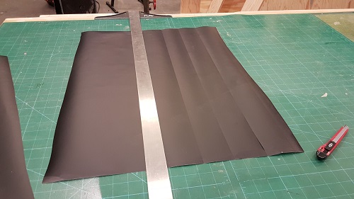
Covered about 1.5 inch of the frame to make sure only the screen is display and not light is going over to make the reflection of the mirror more pronounced.
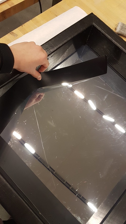
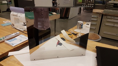
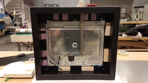
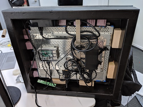
Here is the result:
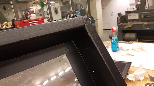
Frame from behind where all the components will go.
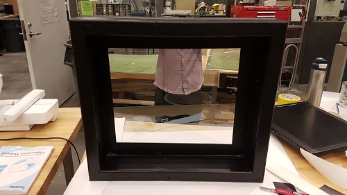
The front of the frame: the mirror.
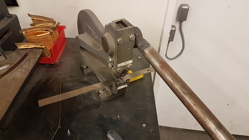
I had to find a way to mount the monitor to the frame, so I used a metal strip and made a L-shape corner to hold the monitor in place and added foam and wood on the sides of the monitor to create some friction for holding it in place.
I used this tool to punch holes in the metal strip.
Used this huge tool to clamp the metal strip in place for bending.
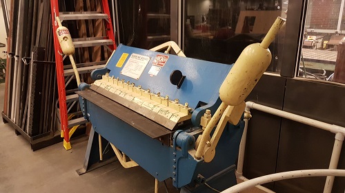
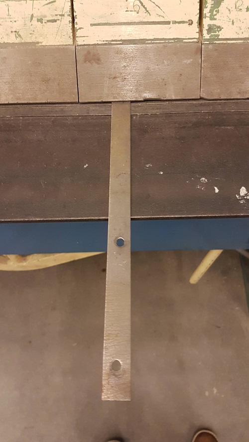
Made a 90 degree to the metal strip to get that L-shape.
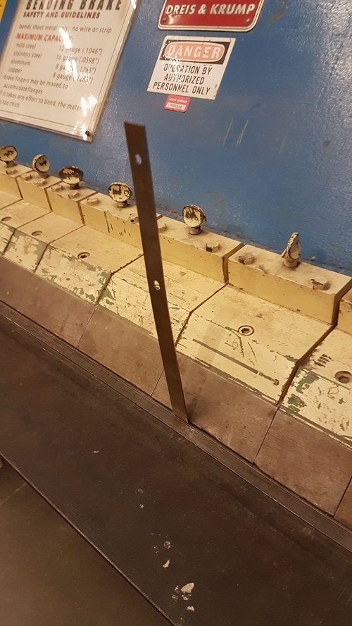
Here is a not so glamorous view of how I mounted the monitor to the frame.
Hello World~ Mirror looking good.
Update: Second week of December (OH NO…)
If you check my networking week blog post, you can see that I finally got to program the BC832 chip all thanks to Sam Calisch! I was initially thinking of using bluetooth communication between the hand-gesture device and the raspberry pi, but then I realized that the raspberry pi has no bluetooth adapter and setting it up might take some time that I do not have and I will need to design and fabricate a new board as well. Besides, it will be fun to try something I have never used before…like the ESP8266 (bad idea?)
To get the important part of my final project started, I tested the ADXL343 board I fabricated a week ago.
I used Neil’s provided code and tried to flash the hex file into the Attiny45 on the ADXL343 board using my USBTINY programmer. Guess what… it did not work.
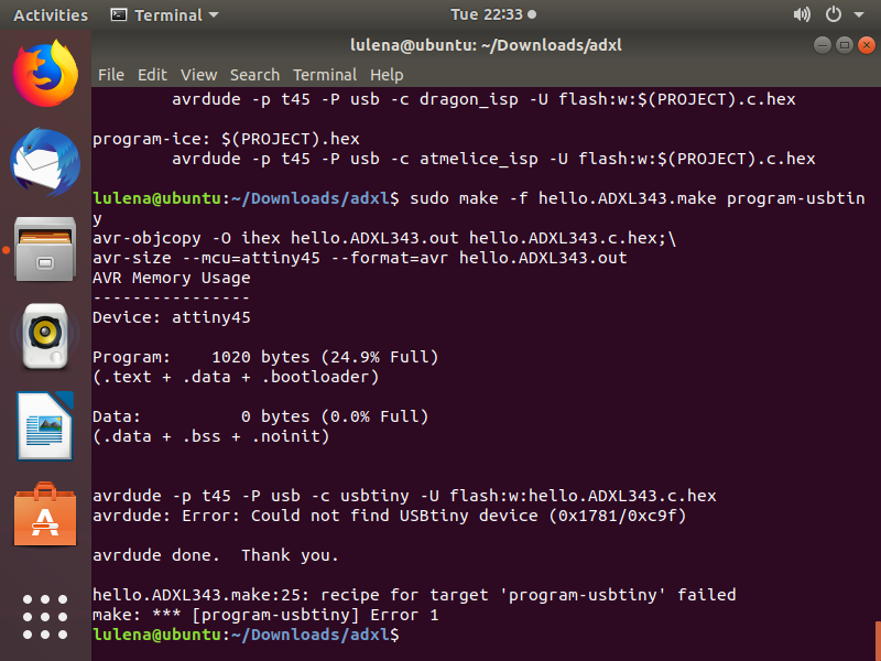
I tested my HC-SR04 board with the USBTINY programmer to see if it was my programmer since it is a RC=-1 error. It worked, so something must be wrong with my ADXL board. I know I did a poor reflow while soldering the ADXL on the board using the heat gun, so I desoldered the ADXL using the heat gun again. It was indeed shorting. I resoldered it back after cleaning the excess solder.
I connected the target board to my computer again and this time, the USBTINY programmer LED is turned on! Seems like good news.
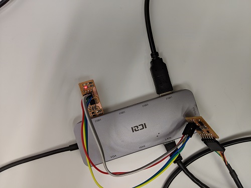
I tried to program the hex file again and this time it worked.
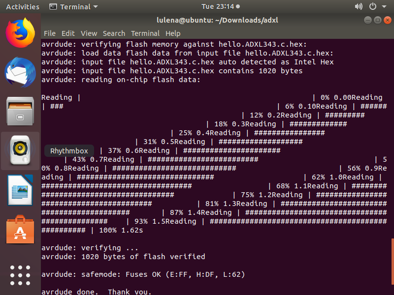
However, the ADXL343 might not be working. Could it be dead from the heat? It is not transmitting any changes to the python interface.
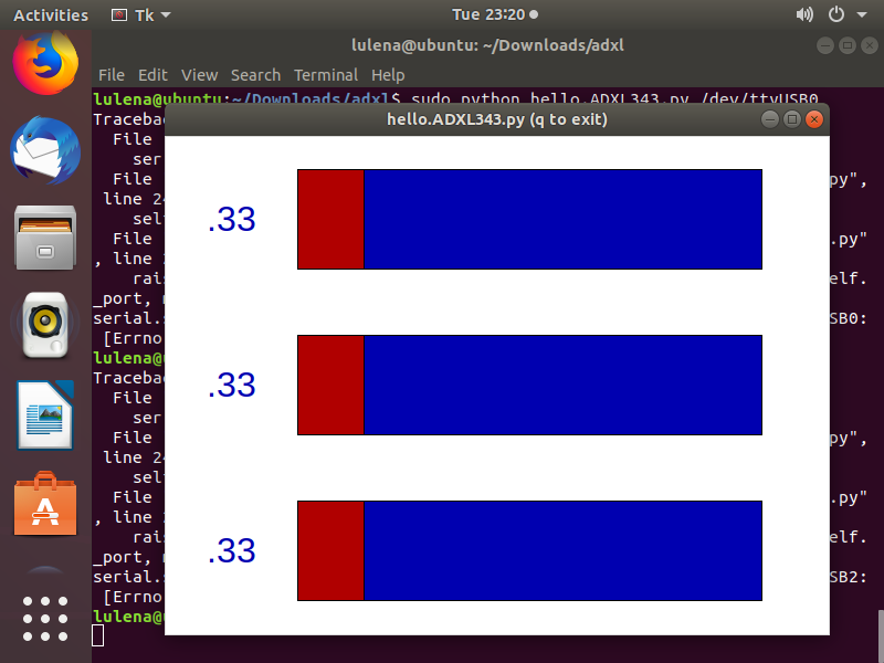
I will have to remake the board and try it again. Once I get all the parts working separately, I plan to combine them together and finish up this project.
LESS THAN A WEEK LEFT!

December 14, 2018
SoundStar: Sound Reactive DotStar LED Strip System
To start with the sound system, I made Neil’s Electret Microphone board from Input Week.
I used my VM running linux to program the code using the USBtiny FabTiny board as a programmer.
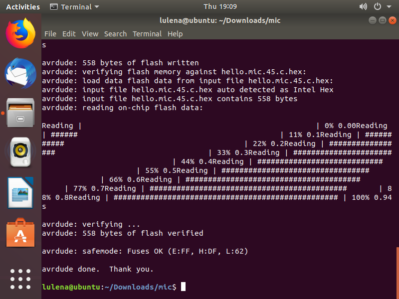
Here is the video showing the microphone picking up sound.
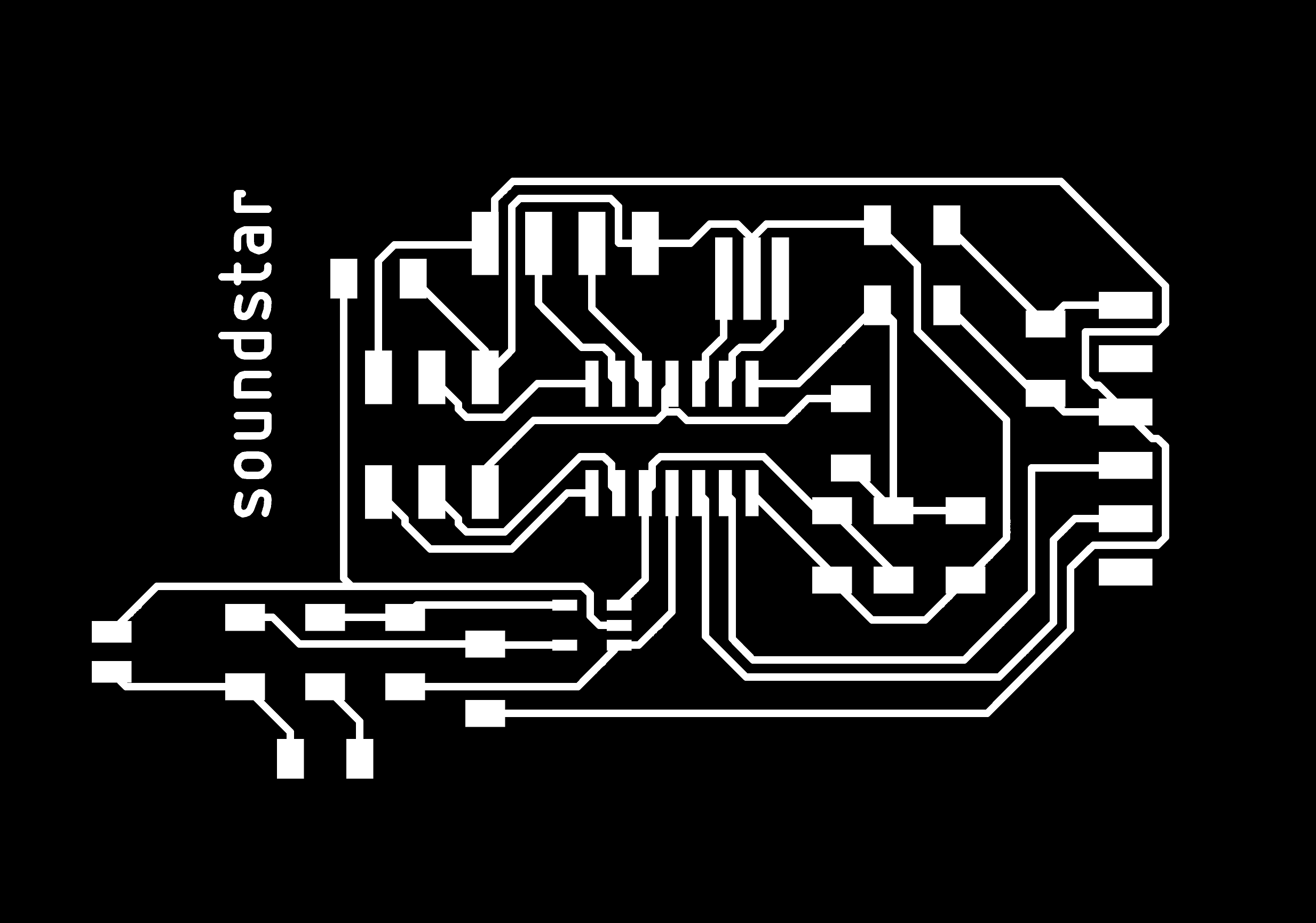
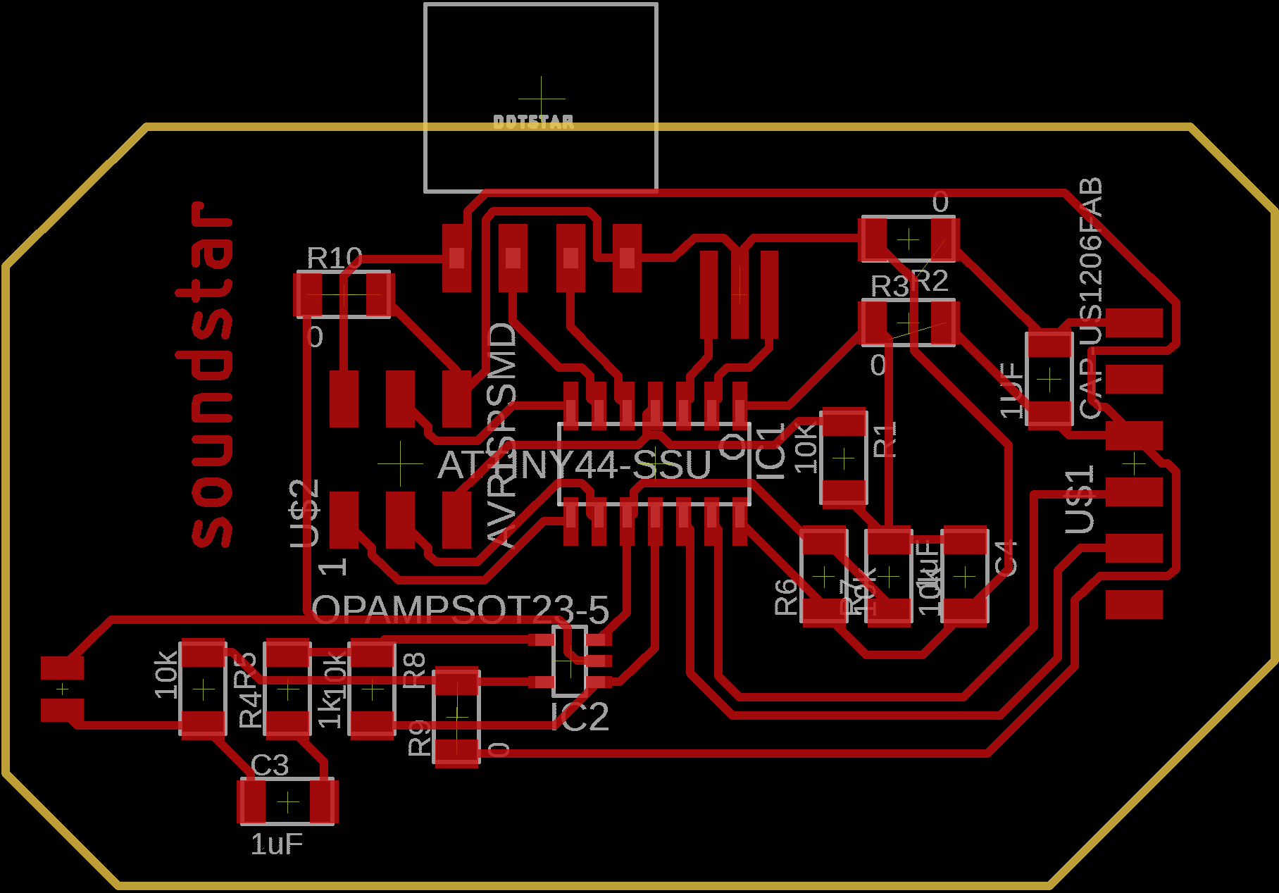
I then designed my own board using an attiny44 with the electret microphone and pins for the LED strips and called it - SoundStar.
soundStar Traces
soundStar Outline
Here is the board diagram
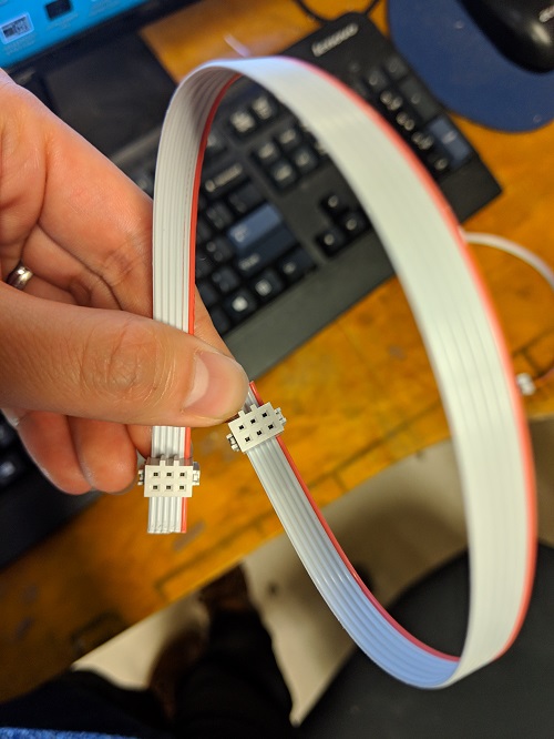
I also finally made a ribbon cable for the SPI connection.
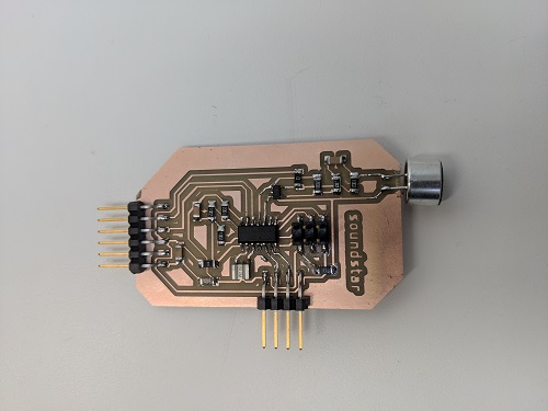
A populated soundstar board
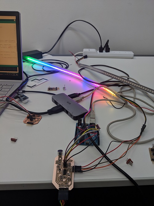
I used the FastLED library to program my LED. I printed the results from the analogRead to the serial monitor and saw that there is a DC Offset with value 512. I substracted that value and used the magnitude of the result for mapping to the LED length. Before that, test the microphone and the LED separately. Then, I had to get familiar with the FastLED library, which is not that easy to use. I ran a couple of demo code until I found the ones that worked with my LED. Then, I modified it enough to get my results.
Electret Arduino Test Code DotStar T84 Arduino Test Code SoundStar Arduino Code
Here is a look of the mess, it worked after several hours of debugging. Also gave up here looking at the non-varying microphone value. Realized that I did not turned my volume high enough to see changes…
The ATtiny44 can only program up to ~32 dotstar LED. The ATtiny84 can do ~72 leds. I initially bought a 144 led per meter DotStar LED Strip and cut it in half to program what I could using the limited memory. Then, I realized that I can just have two in parallel, this will only affect power consumption and not the memory, GREAT!
Then, I thought I could power it using the FTDI cable and connect it to my small power bank. I tested the results by taking it to the 99FRIDAYS party. It lasted the entire party, which was ~3hours.
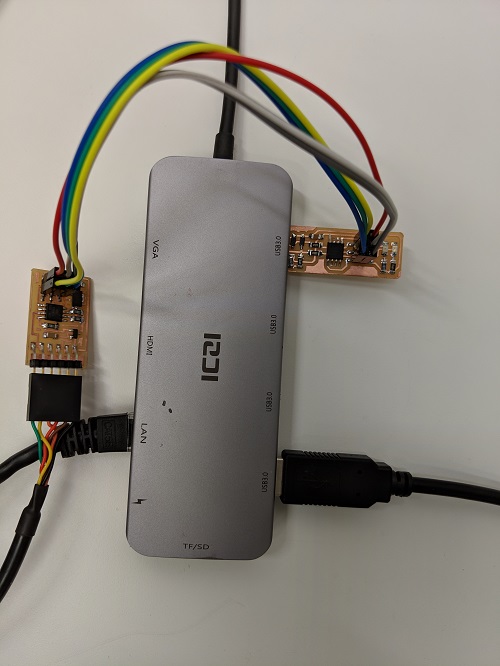
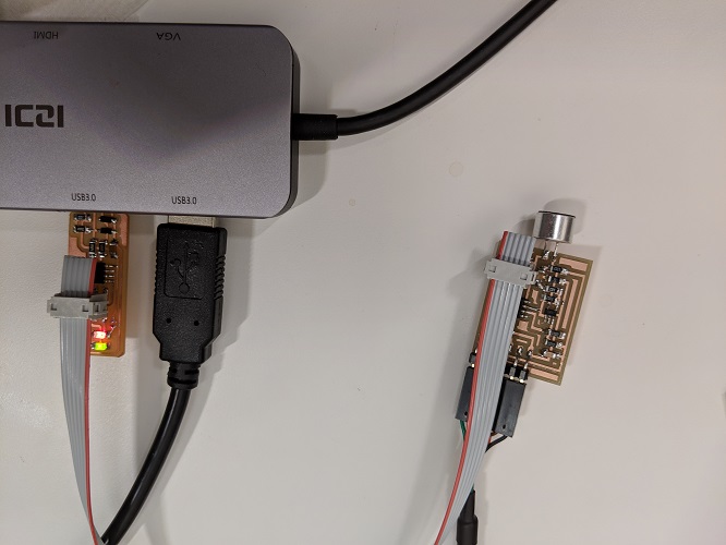
Milling ESP8266 and ADXL343 Boards
I milled out two ESP8266 boards and a ADXL343 board for testing.
December 16, 2018
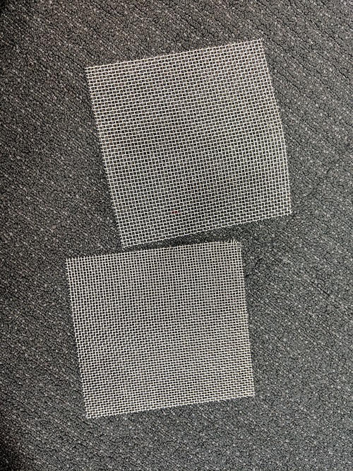
Chicken Wire for LED Lamp
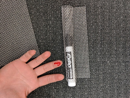
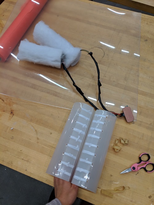
Just having two LED strips hanging does not seem that appealing. I thought I could create an LED lamp showing the increasing amplitude of the sound. Initially, I thought about buying a cardboard plastic tube, but saw that it was around $15! I decided to just go back and make something out of nothing. I found some chicken wire in my labspace and started to test different diameter that I could roll it to make the LED lamp seems taller. I went with the marker diameter and tried to hot glue the LED strip around the chicken wire and failed. Sarah suggested and helped me wrap the two LED strips around the chicken wire tubes using fishing lines.
The chicken wire I found.
Rolling the chicken wire to the diameter of the marker. I cant complete a project without hurting myself. This is one of many times my hands started bleeding.
Hot glue doesnt work for gluing silicon to metal.
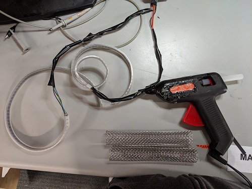
Next thing was to find ways to diffuse the light. I used the sand-blaster after a basic intro by Matt Groh. Sand-blasted a couple of acrylic sheet with different thickness and compared the results (Lost the images). After testing it, Sarah suggested me to use some of her cotton fabric she bought for her ThunderCloud Project. I used the hot glue and glued some of it around the LED strips. Great.
Mirror Cable Management
The rest of the night I worked on mounting all the electronics on the frame and on cable management. I realized I will need to have a hole for the power cable to go through the frame. Will do that tomorrow.
December 17, 2018
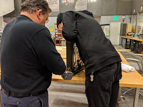
Mirror Frame - Drilling hole for power cable
First thing in the morning, I went to the machine shop and asked Tom for help with drilling a hole through the frame. He showed me the drill bit I should use.
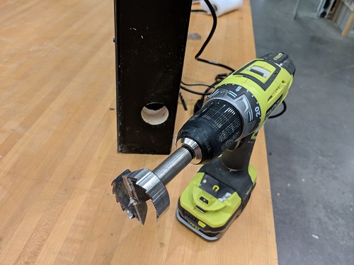
Then, we realized that it was still not big enough for the power header to go through. John came and helped me with it.
Now, just need to make the back lid with hinges that I found in the machine shop.
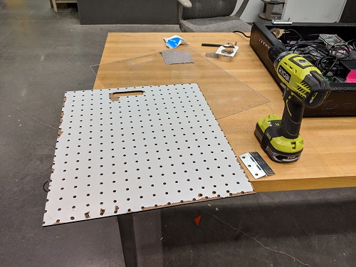
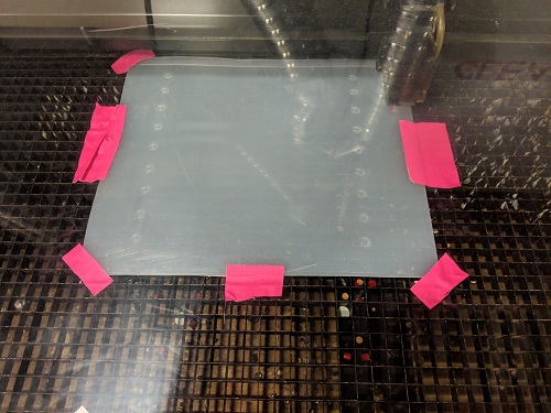
I lasercut some thin acrylic and it cracked. It was fragile, so I used the pegboard I bought from Home Depot.
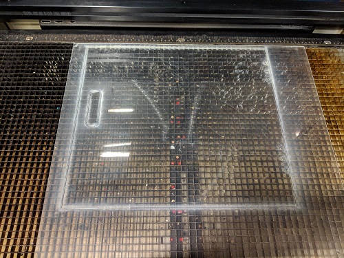
LED Lamp tube
After asking people around for thin acrylic material that I could bend, some suggested to use polycarbonate plastic for better results when bent. I lasercut what I could and used yarn to keep them in shape.
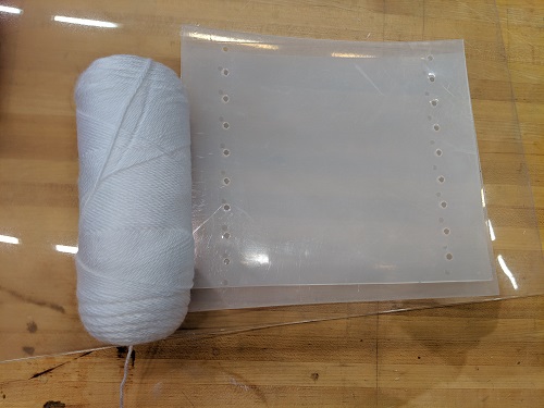
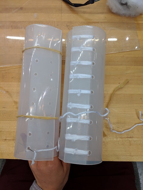
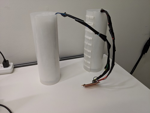
Here is the LED lamp, still need to find a way to better hide the wires.
December 18, 2018
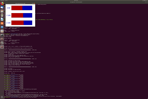
Testin ADXL343 Board on Linux
I struggled again with reflow soldering the ADXL343 on the board. I tried several times to get it in place. I tested the board using the same code provided by Neil on my VM running linux. I used the FabTiny board as the programmer. It finally worked!
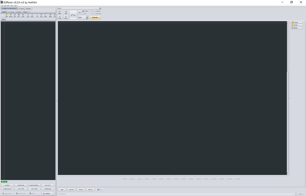
Testing ESP8266 on Windows 10 with ESPlorer IDE
I made two of Neil’s ESP8266 board.
- Install Java SE Runtime Environment
- Install ESPlorer IDE
- Install required libraries listed on ESPlorer website: Java Simple Serial Connector
- Now you can run the .jar file which will open up ESPlorer IDE.
- Connect ESP8266 board with FTDI cable to the computer.
- Find correct COM port and connect with the ESPlorer IDE with baudrate of 115200. Click the “Open” button to start communication.
- It will get stuck with the message saying, “Communication with MCU”. I had to keep the port open and unplug and plug back in the board in order for it to recognize it again. Could be because of initial communication signal problem. It did the same to both of my boards.
- Send the AT commands using the terminal on the ESPlorer IDE and send button.
Using the ESPlorer IDE for programming the ESP8266 on Windows 10.
ESP8266 connected to MIT Guest Wifi network.
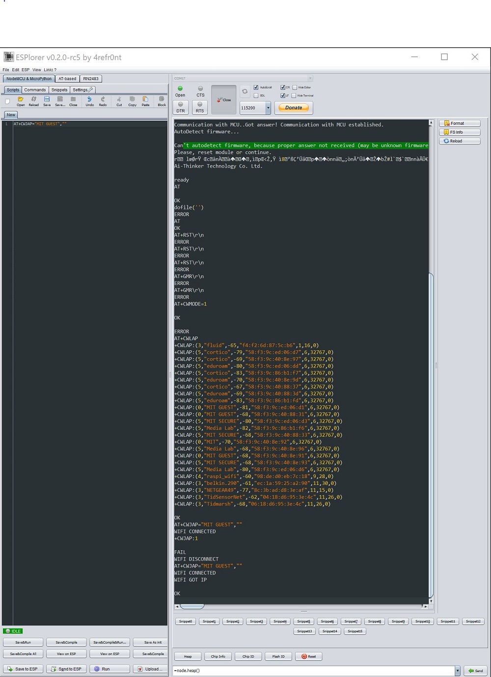
I tried to follow Neil’s video showing communication between the board and the localhost socket terminal. Since I don’t know much about client/server/socket/etc… The only part that I was able to get working was anything that I sent to the ESP8266 board using the AT protocol with the ESPlorer IDE. I could not understand what was going on on the localhost socket terminal. Thus, I tried my own methods using basic knowledge adquired from previous projects.
I got wifi connected to “MIT GUEST” with password “”, since it doesnt have one. I did try using the Arduino IDE, but couldnt figure out how to program to it via the FTDI pins; Good starter tutorial on how to use Arduino IDE for programming the GPIO of the ESP8266 ESP-12E, also known as NodeMCU ? ESP8266 Arduino IDE. Also tried to flash a new firmware following this blog post, but it did not respond…
I am not well verse with networking system, so this is all new to me and I have no idea what I am doing. Will have to spend some more time working with the BC832 and ESP8266, they seems to be very useful for IoT applications. I also soldered an ESP32 and have an nRF24L01+ (2.4 GHz ISM) as well. I have used the HC-05 and HC-06 bluetooth before, but I want to try making my own board. All of these are for future work.
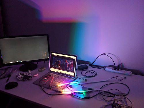
Results
SoundStar: Sound reactive DotStar LED
Here is the almost finished sound reactive dotstar led, SOUNDSTAR. Just missing the final touch.
Future Work
- Gesture Device
- Smarter mirror
- Better sound sequence
Budget
Most things were found in the lab and surround area for free. Almost all electronics were provided or I had it from previous project. Mainly spent on buying material for the frame.
I bought way more than I needed:
- 1X Wood Glue 3.97
- 2X 5/4 X 4 8FT COMMON BOARD 15.38
- 2X4 WHITE PEG BOARD 9.57
- FLAT BASIC BRUSH 2.97
- WHITE PRIMER PAINT 9.98
- BLACK PAINT 8.46 ————————————Total ~55 including Tax Later, I realized that we had paints and wood glue in the shop.
Additional cost if you were to buy them.
- New LCD screen with HDMI port - $100
- Raspberry Pi 3B kit - $50
- Extension cable for power - $15 —————————–Total ~$165
Having a budget of $200 should be more than enough for this project.
For the sound reactive system along:
- Attiny84 2.02
- Electret digital mic 1.25
- resistors and capacitors ~ <1.00
-
Op Amps 2.31 ————————————-Total ~ $8
- LED Dotstar $50 The led strip could be made with RGB smd led. It wont be addressable but much cheaper.