Week 1. Computer-Controlled Cutting
This week we got trained in the Center for Bits and Atoms machine shop in the MIT Media Lab building. We also learned about version control using git. I am currently using the Windows Bash Ubuntu terminal to do everything except for writing these blog pages. I am using the Bracket text editor for that.
Characterization of the Lasercutter
For the group assignment, we had to characterize the lasercutter in the machine shop. Suryateja Jammalamadaka, Yusuf Ahmad, Ravi Tejwani, and Zijun Wei were my teammates for this assignment (They are great!).
We all worked together to come up with the design for testing and then analyzed the results to make sure we were on the same page. Yusuf wrote everything down on a google document shared to us. He wrote very detailed description and I will try to summarize the process here.
We started off discussing what we needed to figure out about the laser. Our individual assignment was to make a press-kit, something like pieces of a puzzle that could fit together to create a tri-dimensional object. In order to make the pieces fit together, we needed to know the width of the cardboard we were using and the slots offset. Since the laser burns throught the cardboard to create the shape we want, it creates an offset or kerf that needs to be taken into account in the design to make sure we dont get loose pieces.
Width of cardboard was 0.165 inches (approx. 4.19mm). I am not used to thinking in inches. SI UNITS, PLEASE!
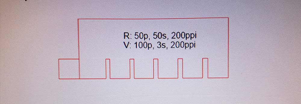
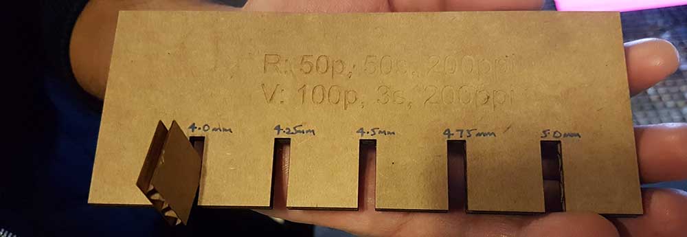
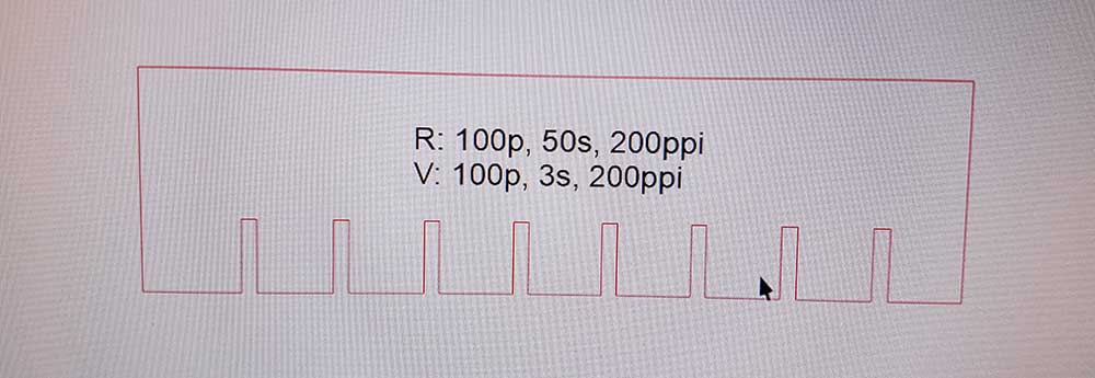
Below is the design of our first test, starting off with a 4.0, 4.25, 4.50, 4.75, 5.0mm slots. The design was done with SolidWorks, then the file was saved in the DXF format and transferred to the CorelDraw software.
From there, we select the settings for raster and vector cut. During the training, we were told that the good settings are as follow:
- Vector Cutting:
- Power: 100%
- Speed: 3.0
- PPI: 200 fixed
- Outline (lines): Hairline
- Raster:
- Power: 50-100%
- Speed: 20-80
- PPI: 200 fixed
- Fill: color based on priority in ‘PEN’
See below for test results
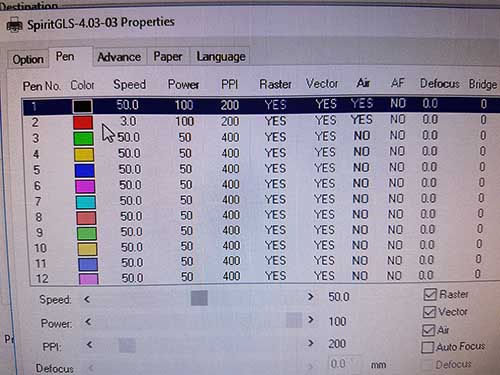
We decided to set Raster at 50% Power, 50 Speed, and 200 PPI, and Vector cut at 100% Power, 3 Speed, and 200 PPI. Those settings can be set once you hit ‘Print’ in CorelDraw. We will see the screen below. We need to go to ‘Pen’ and set the power, speed, ppi, as well as MAKE SURE ‘AIR’ is checked (it is not by default). The color that we see are the priorities, it will first execute the black color settings, then red, green, yellow, etc. For that reason, we have Raster in black, because we dont want the pieces to be cut first (it will move if we rasterize after cut ~no good). Okay, once everything is selected, we hit ‘Print’, CorelDraw will send the job directly to the GCC Laser Pro Spirit GLS laser cutter.
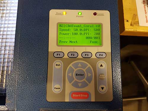
The job will show up in the laser cutter LCD screen with the file’s name and the settings. We align the cardboard and manually focus the laser by using a tool (forgot to take picture) and just use the up and down arrow to move the tool until it barely touch the cardboard. Now we press start twice with the lid open, the laser will start moving but won’t actually execute the cut. This step is just to make sure we have the cardboard aligned to were we want. Now, we press Stop, close the lid, and Start again. This time, it will start cutting.
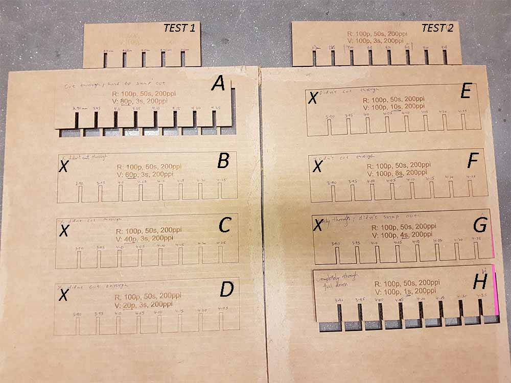
The picture below shows the results of the cut. It snapped out easily, but the Raster is a bit too hard to see.
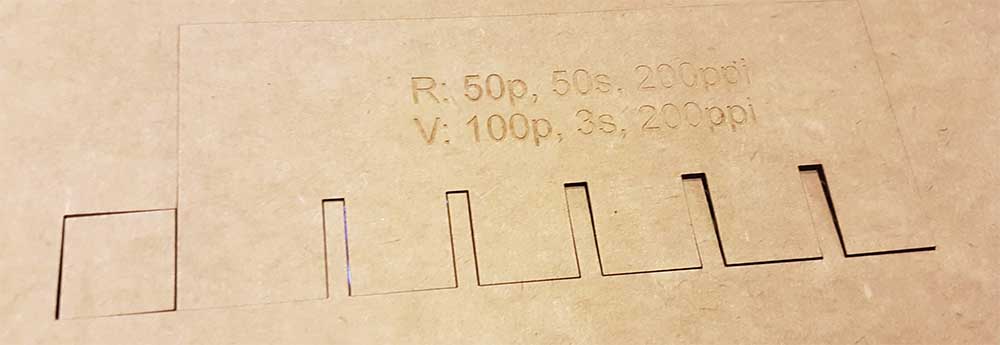
We figured that at 4.0mm the cardboard fits pretty well, 4.25mm is a bit loose.
Based on these results, we decided to do a second test and decreased our incremental steps to .15mm - starting from 3.90mm to 4.25mm. We also increased the Raster power to 100% to make it easier to see.
These are the two prints we did initially.
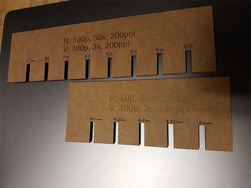
We then used the same design to test variation in speed, and power for the Vector Cut only.
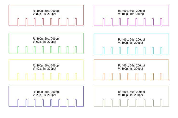
The results can be seen in the image below, which can be summarized as followed:
- Best Vector Cut Settings:
- Power: 80-100%
- Speed: 1.0-3.0
- PPI: 200 fixed
- Best Raster Settings:
- Power: 100%
- Speed: 50
- PPI: 200 fixed
Laser Cutting
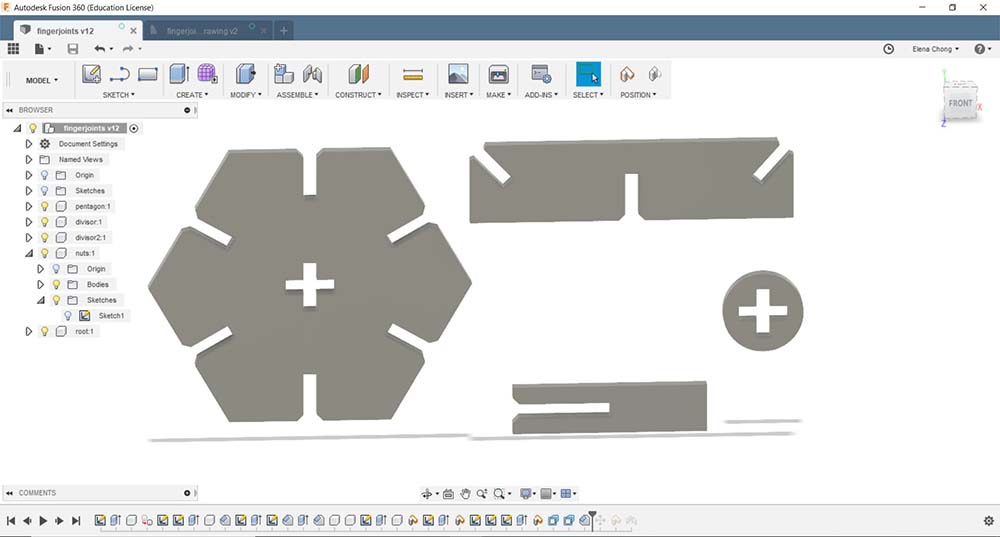
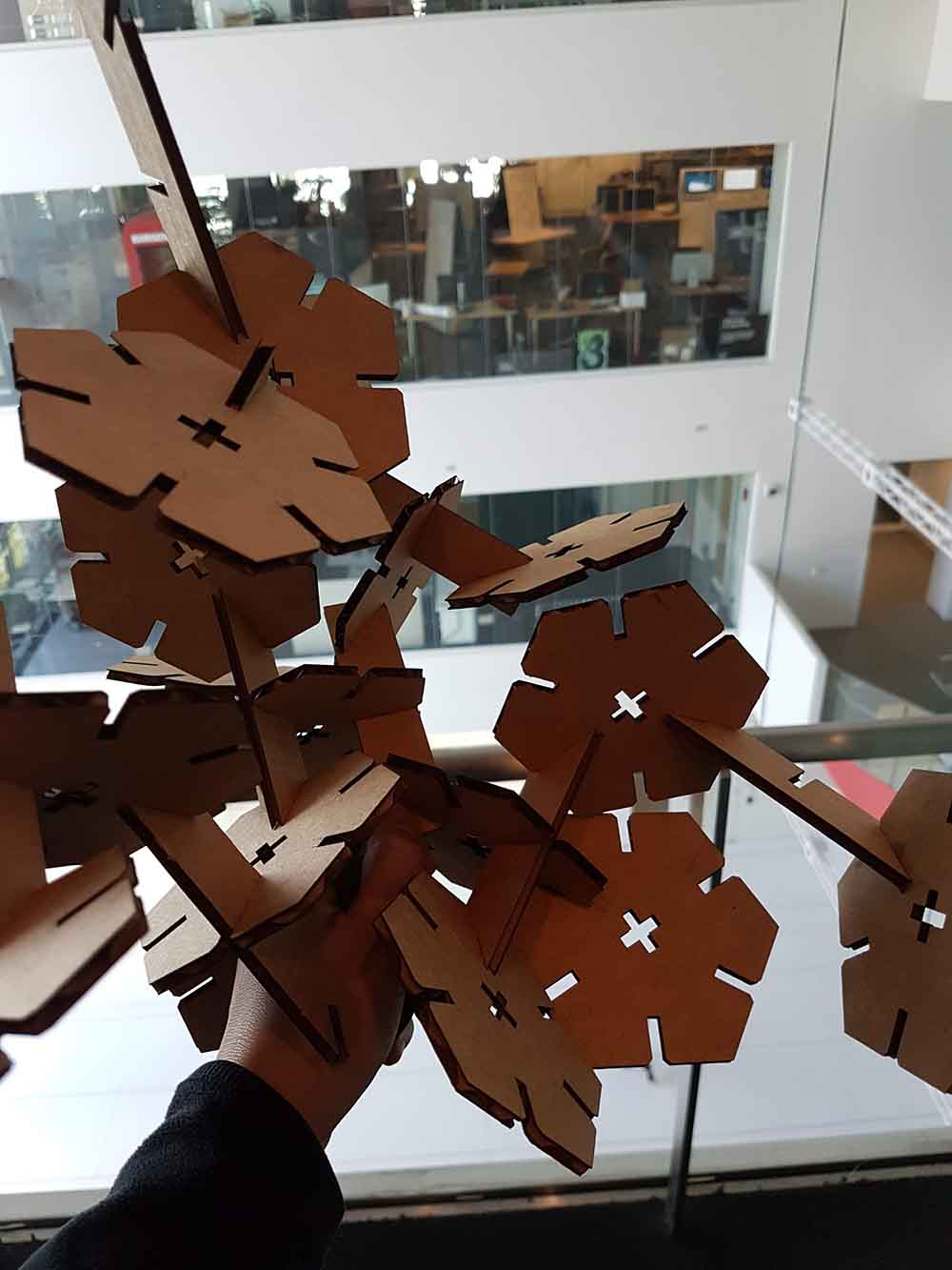
For the press-kit assignment, I decided to search online for inspiration for my own design. Initially, I thought about making some kind of stackable hexagon boxes that could be placed on my desk, however, I decided to explore the idea of making a press-kit without a specific 3D object in mind and see what I could get. I used Fusion 360 to design the all the pieces. I started off with a hexagon and added slots to the midpoint of each side. In addition, I added a ‘+’ in the center of the hexagon to see if I could interconnect different pieces through the center. Also made divisors to separate each hexagon and a circle with ‘+’ to fix the hexagon in place. All of these pieces are illustrated in the picture below.
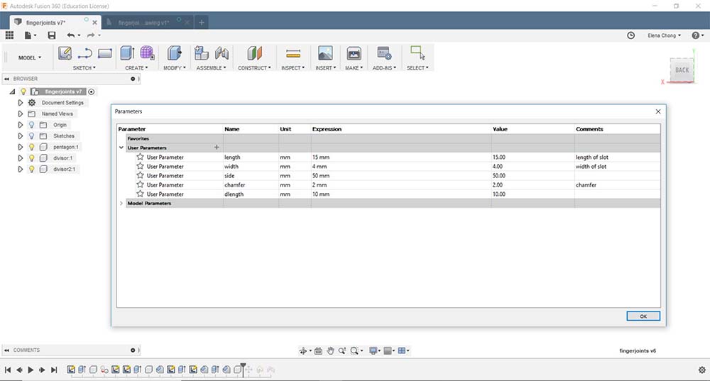
Here are some parameters I used during the design of the pieces.
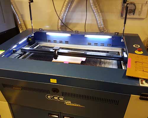
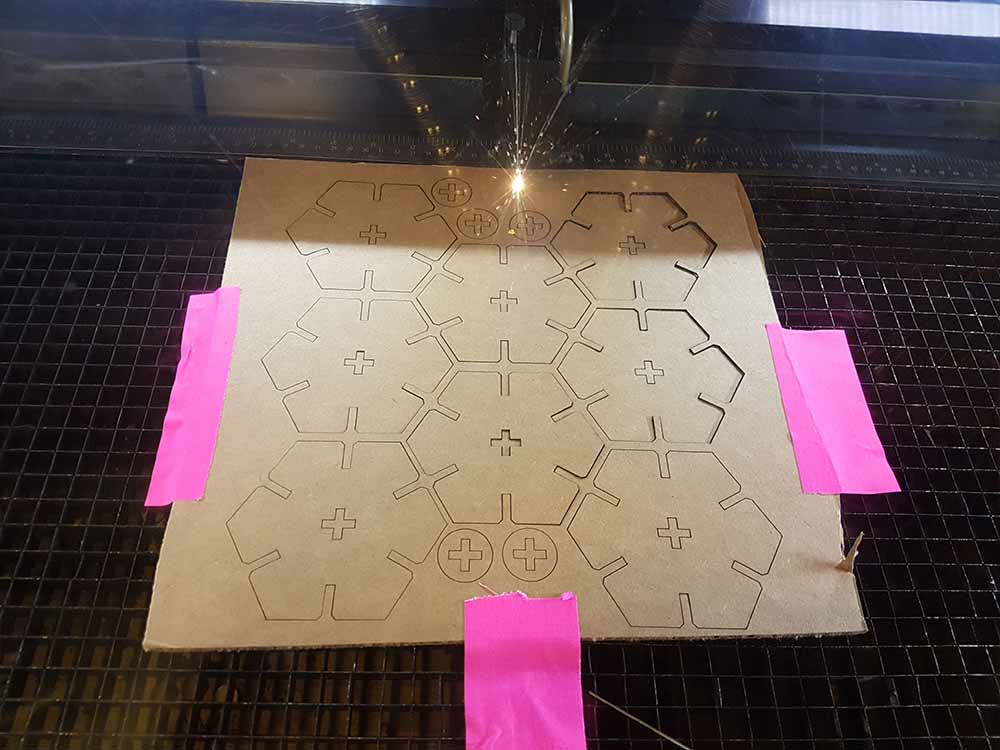
After choosing the correct settings from the characterization, I sent the job to the laser cutter. Below you can see it been cut.
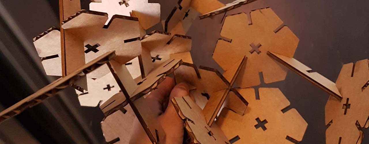
I snapped out the pieces and put something together. Is this what people call arts? It looks good because of all the geometrical shape I guess. I was trying to see if it could make it stand on two hexagons while I stacked more pieces on top and see when it collapses.
Next thing I want to do is to add ‘LIVING HINGES’ to the center of the hexagon pieces to make them move a bit.
Vinyl Cutting
From the training, we learned that we have to stick the material inside the machine and move the rollers to the white region and clamp it (Should have taken more pictures). We select sheet: piece instead of roll and press enter for it to get the dimension of the material W,H. We input this on CorelDraw to get the correct dimension for placing the art. Then we go to print, get dimension from machine automatically, and hit print. The setting has been set as a template, so we dont need to do it ourselves. Just in case, it is 20cm/s with a force of 80gf.
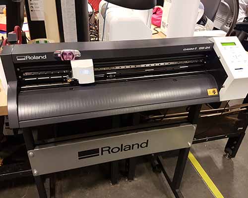
We used a ROLAND GS-24 Vinyl Cutter.
For the assignment, I decided to just do a simple design of the flag of Panama!
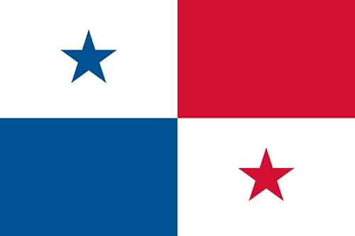
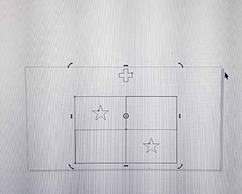
I designed the flag in Adobe Illustrator with a cross at the top as a guide and saved each color in a separate svg file. These files did not transfer well into CorelDraw, it showed as the entire flag instead of each color piece, so I just cut the entire flag as one single piece and then took out excess material, see pictures below.
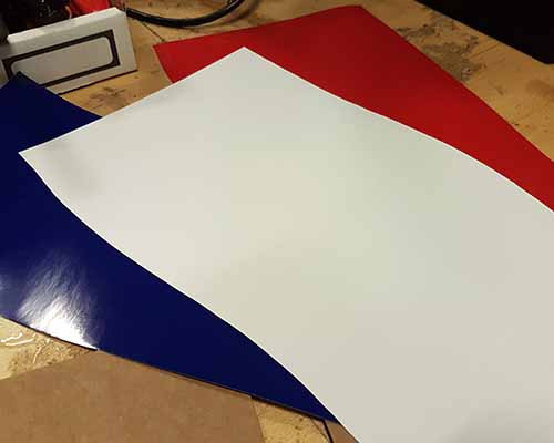
These are the vinyl material I used in red, blue, and white. White for the background.
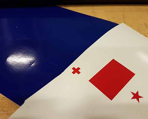
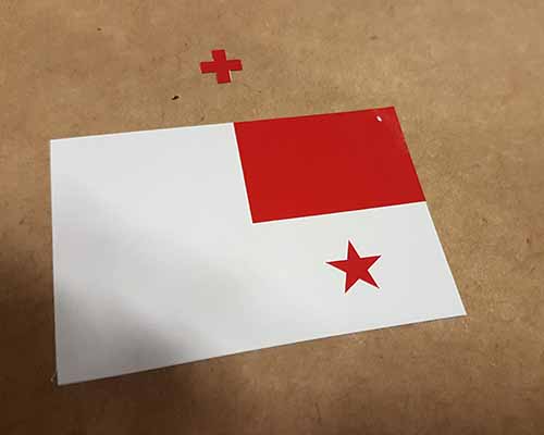
This is the second cut, you can see the blue is cut but with all the excess material. The excess material in the red vinyl has been removed.
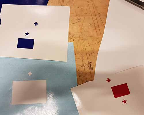
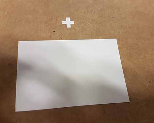
After cutting all the pieces and removing the excess materials, this is what I got:
I transferred them with transfer paper and pasted them on a cardboard since I didnt have a laptop.
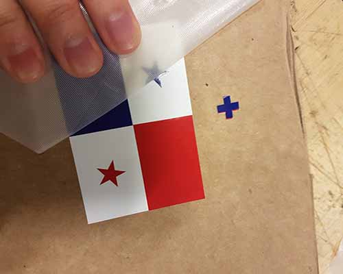
This is the final result with the Roland GS-24 Vinyl Cutter in the background!
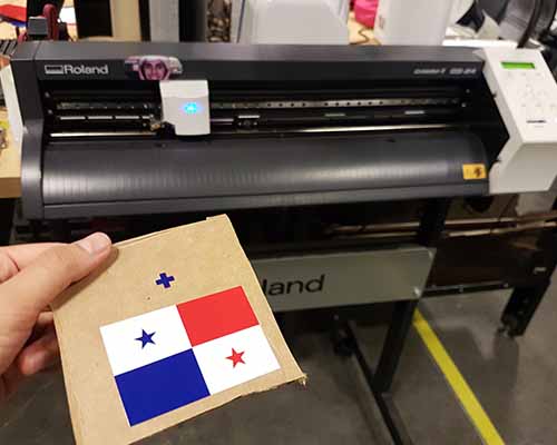
¡Viva Panamá!
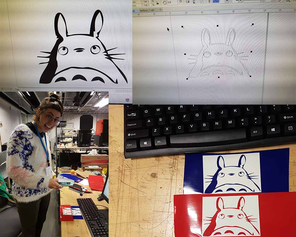
One last comment, while I was helping Oceane with her setup, we tested a vector fill vs. vector outline. We noticed that it really does not matter, the results is still the same. The machine will just cut the outline regardless of if it is a fill (left Totoro) or an outline (right Totoro) of the art. To see what I mean, look at the picture below.
Note: All the works here were done by Oceane, I just reminded her of how to use the Vinyl Cutter.