Week 12. Networking and Communications
Fabrication
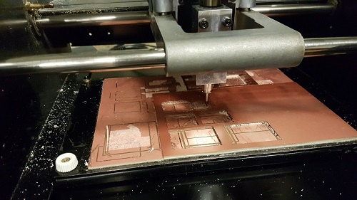
For this week, I decided to learn how to use the nRF52832 (BC832), a 2.4GHz Bluetooth with an MCU. I followed this tutorial and used the Modela to mill out 5 of the same board (Fab-BC832). Since I have never drilled through the FR1 board before and have never done reflow soldering, I made sure I had enough to play with in case of mistakes in the first few. I decided to not make my own board yet because I plan to use the BC832 for part of my final project as well. If I do not understand how it works, my own board will probably be difficult for me to troubleshoot if I encounter any problem.
Here is the Modela milling one of the several board I fabricated. Throughout the process, we learned how to get rid of the pads we did not want by tricking the mods to mill away the copper to prevent shorting.
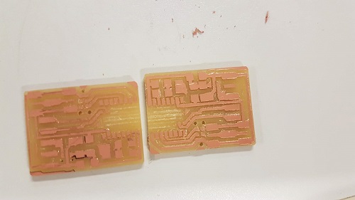
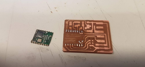
Two of the resulting boards that milled correctly. Some of the boards did not get the three holes for the jtag milled through because the file contained the outline together with the holes and we realized that by setting the “path order” to reverse, we could get the holes milled before the outline.
Soldering - Reflow
This is a complicated board to solder because it has small pads underneath.
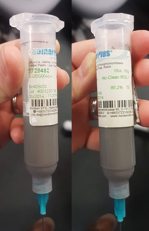
I asked some of my labmates to teach me how to do reflow soldering. We used a soldering paste with SN63/PB37 (lead!).
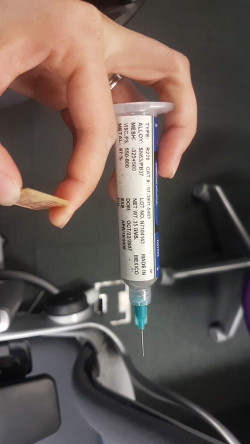
Then, I used the pressure machine (forgot the name) to slowly press out a small amount of soldering paste from the syringe on each pad. The picture below shows a close-up using the camera on the pick-and-place machine.
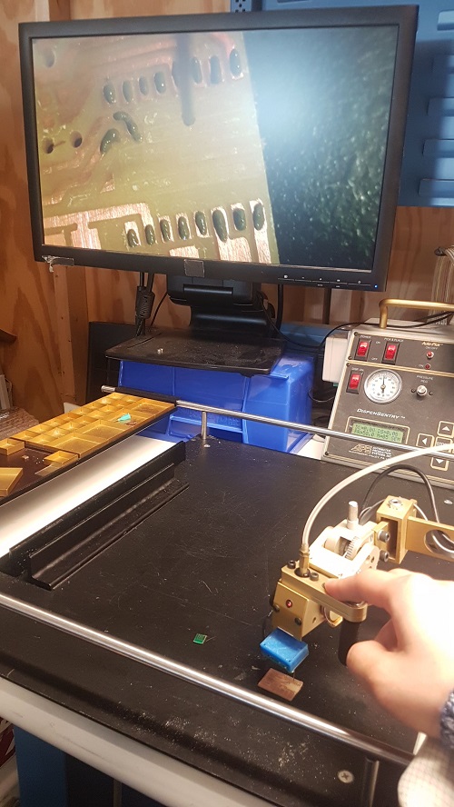
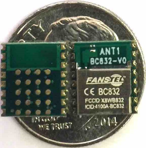
Next, I used this pick-and-place machine to pick up the BC832 chip and place it on the fabricated board.
It is actually hard to position the chip correctly on the board because the camera is displayed at an angle. It might be easier with the tweezer.
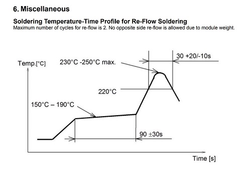
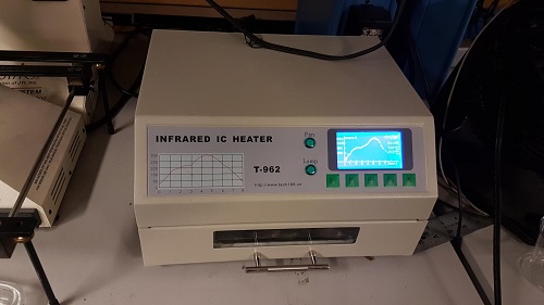
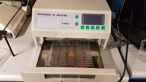
After that, I used the Infrared IC Heater machine that we got in Resenv to heat up and melt the soldering paste. I looked up the temperature chart of the BC832 in its datasheet and found the closest matching chart in the machine. Usually, due to surface tension and physics, the soldering paste find its way to the pads on the chip. Once it is cooled down, it should be perfectly solder.
The board showed a bit of discoloration and the chip did not solder correctly onto the board. I decided to use the heat gun for desoldering and ended up taking the chip apart as seen in the picture below.
Another soldering attempt
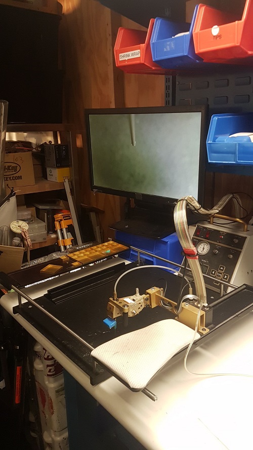
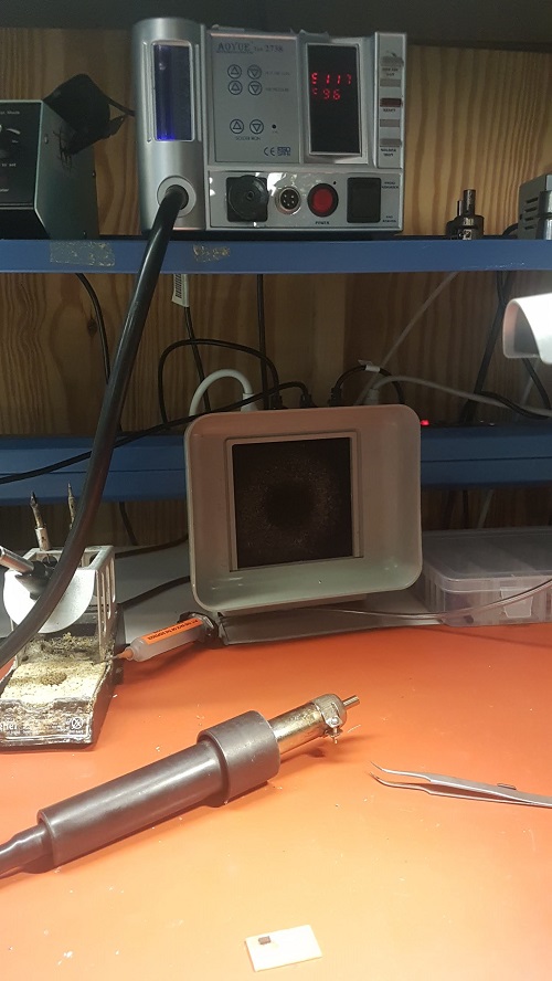
This time, I asked Brian Mayton about the discoloration on the FR1, apparently, the FR1 is not very heat-resistant. He suggested to better not use the Infrared heater but the ZT-1-BGS machine shown below for melting the soldering paste. He also showed me a lead-free soldering paste that I could use. Thus, I did all the previous process again, but heated it on the other machine.
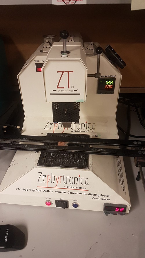
Here is a close up. We set the bottom heater to around 100C and the top heater to around 220C. We move the top heater right on top of the chip and wait for around 45s to make sure the soldering paste is melted. (We actually moved the top heater much closer than this picture. Almost touching-the-chip close).
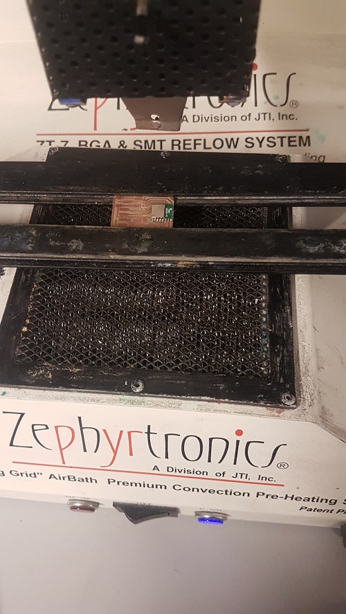
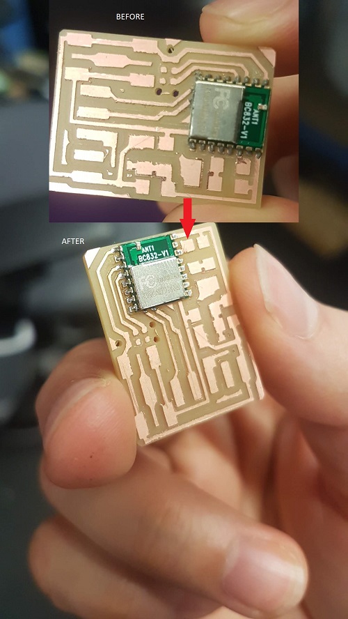
Here is a beautiful before and after of the soldering paste curing.
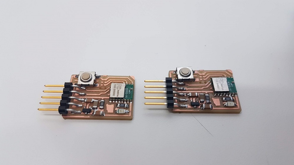
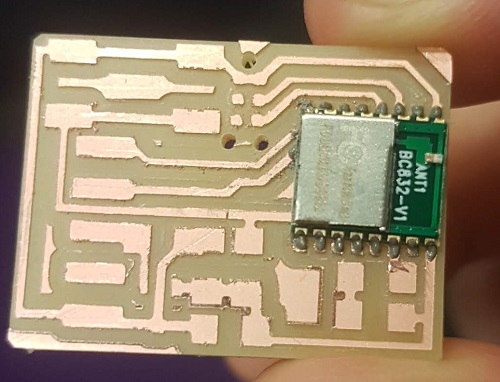
I populated two boards for testing because we have no idea if the pads underneath got soldered correctly. The only way to know is when we start programming and debugging. Wish me luck!
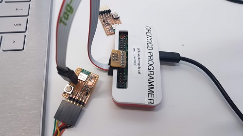
Programming
According to the tutorials there are two ways of programming the bootloader onto the chip. One is by using the J-Link programmer, and the other one is by using a Raspberry PI with OpenOCD in it. I was hoping to programming it using the J-Link but realized later that we dont have it in the 043 room. Will Langford was able to provide me with a raspberry pi zero apparently with the openOCD already setup. I tried it by providing power to the RPI Zero and waited for about a minute for it to fully boot up. Then I used PuTTY to SSH using the hostname: raspberrypi.local or pi@raspberrypi.local. It did not work! I got a message back saying that the host does not exist. I tried a couple more times trying different alternatives for the hostname and it still did not work.
I found a mini HDMI to HDMI adapter in my lab space and used it to hook a monitor to the RPI Zero, then I realized that I did not have a microusb to female usb adapter for the keyboard. After a while, I just gave up in using the RPI for the day. Will try it once again later and will also borrow a J-Link to test it out. I WILL MAKE THIS WORK!
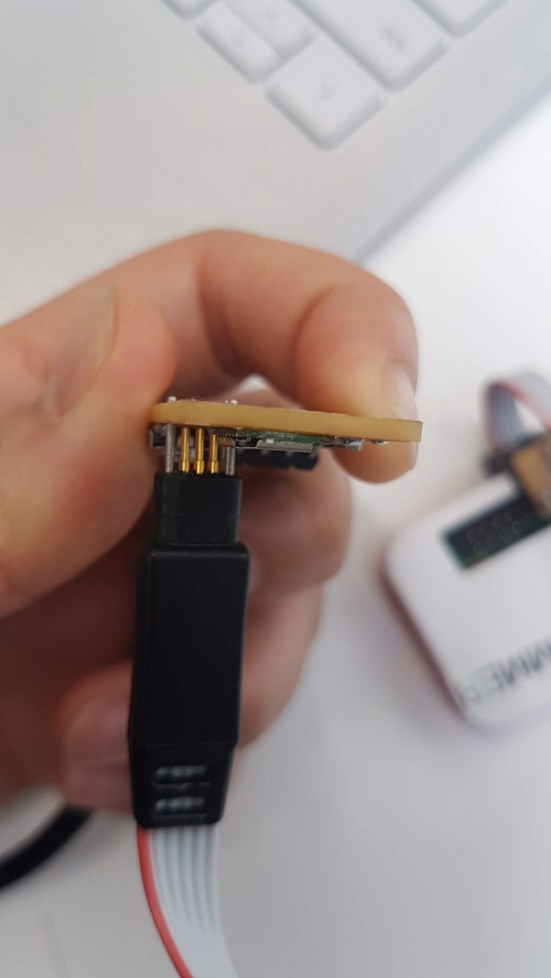
Interesting how the J-tag works.
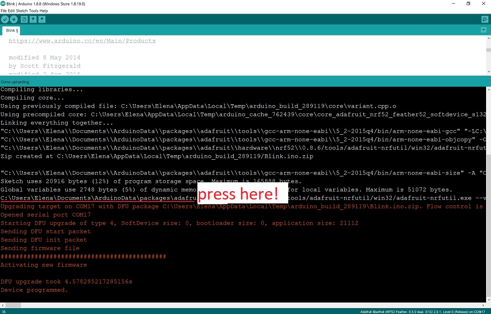
Update
After I talked with Sam Calisch, we were able to successfully program the BC832. Both boards worked! The trick is pressing the button at the right timing!
Need to press right before the orange text shows up.
I also realized that the Fab version of this board does not allow for Bluetooth communication. You need to use the 32.782kHz crystal in order to use the Bluetooth. Tomas Vegas and Abhi from Fluid Interface tried it without the crystal and could not get it to work.
I also tested the ESP8266 wifi module during the final project testing. See my documentation here