Week 2. Electronics Production
Machine: Roland Modela MDX-20
End-mill: 1/64” for traces, 1/32” for outline cut
Software: mods
Components and tools used: FR-1 copper board, 1x ATtiny45, 2x 1kΩ resistors, 2x 499Ω resistors, 2x 49Ω resistors, 2x 3.3v zener diodes, 1x red LED, 1x green LED, 1x 100nF capacitor, 1x 2x3 pin header, multimeter, solder station, double-sided tape.
References: Class site, Brian’s FabTinyISP
Characterization of the Roland Modela MDX-20
For this week individual assignment, we had to use the small milling machine (Roland Modela MDX-20) to fabricate a version of an AVR ISP programmer. I followed Brian Mayton’s detailed documentation to make mine. Thanks Brian!!!
For the group assignment, I worked with Zijun, Teja, and Ravi to characterize the milling machine.
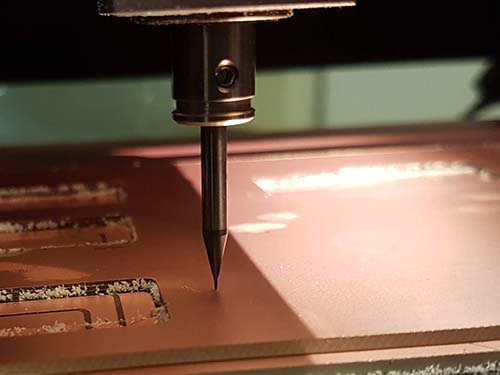
The first thing we did was to put in the 1/64” end-mill for milling the traces in the Roland Modela MDX-20. We then did calibration by loosening the two screws that hold the end-mill tight and pressed the DOWN button on the Modela MDX20 until the tip of the end-mill ALMOST touched the surface of the board, then we gently put the tip on the platform to avoid breaking the end-mill (they are expensive).
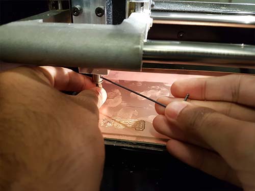
Use a piece of paper to verify that the tip is touching the platform. The paper should not be able to slide under the tip.
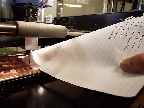
This is how it should look like, and it is ready to print.
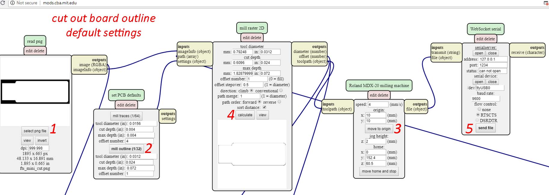
Now, we go to the custom-made program made by Prof. Neil Gershenfeld and his group called Mods and do the following: Right click/programs/open server program/ look for Machine/Roland/mill/MDX-20/ and click on PCB. Get the .png files for the trace and outline of the FabTinyISP on Brian’s site. trace.png, outline.png
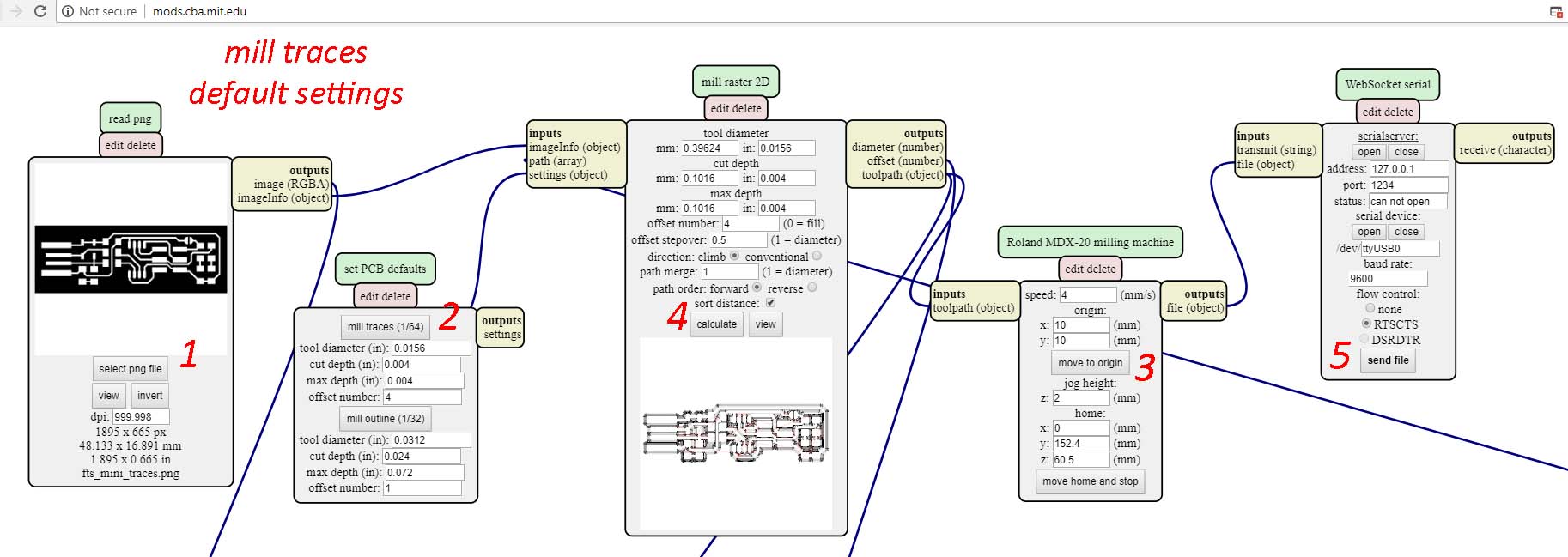
Open the trace png file in mods, click on mill traces (1/64), then move to origin (make sure you input the x,y coordinate that better match your starting point for the board), then calculate, and finally, if the origin is right, press SEND FILE to print. Oops, the image below shows the trace for the FabTiny and not the characterization board, but you get the idea. It is the same process for milling the traces!
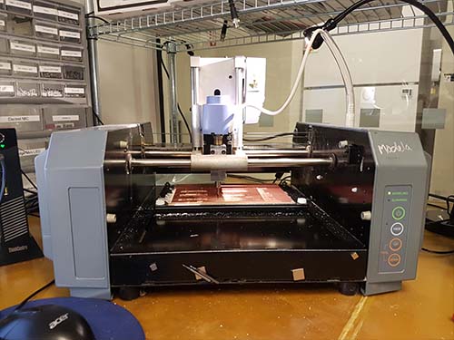
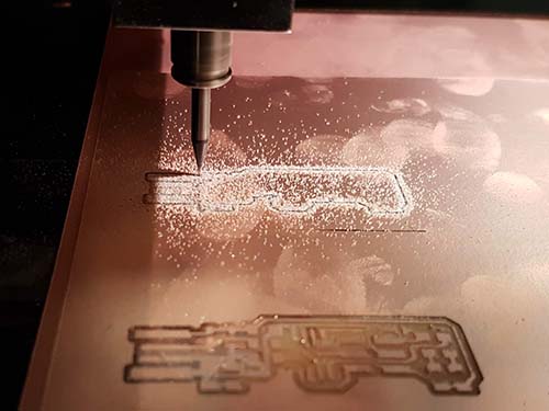
Now see the Roland Modela MDX-20 in action!
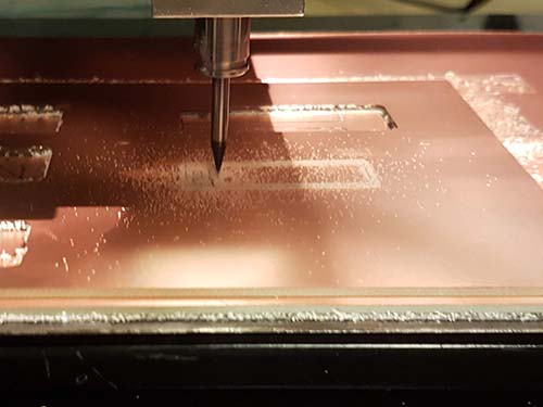
Once the milling is done, we have to cut out the board by using the outline png file and do the same as above on mods but now we need to press ‘mill outline (1/32)’ instead. Remember I am using the FabTinyISP outline instead of the Characterization board for illustration. Just make sure you select the correct png file.
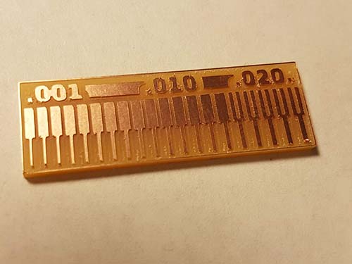
The resulting characterization board. We can see from the above part the defining gap and below the resolution and width of the trace. Gap width of .17 of an inch and traces could go to 1 mil if I am not mistaken. Need to test it myself by designing my own eagle file later to confirm.
Making the FabTinyISP
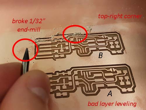
As mentioned in the beginning of this blog, I followed Brian Mayton’s detailed documentation on how to make the FabTinyISP. Following the same calibration process as mentioned above, we tried to mill several boards at once to reduce time of calibration since we need to do it once for every change of end-mill. We made sure everyone had the opportunity to try the calibration correctly without breaking an end-mill. Note: every time you mill you need the 1/64” end-mill and every time you cut you need the 1/32” end-mill, so if you do one board at a time, you will need to recalibrate every single time you change the end-mill!!! This was actually a mistake, it may be better to just cut one at a time to avoid breaking things.
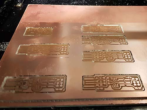
Unfortunately, we broke two 1/32” end-mill while trying to cut out the outline of the top right board. One of the end-mill seemed to have broken in half but was somehow still functional, so we just continued to use it until it broke, then we used a second one, which sadly suffered the same fate. I think it broke because the platform, the sacrificial layer, and/or the FR-1 single layer copper board were not lay perfectly flat on the surface. Making the end-mill go down much more than the other cuts.
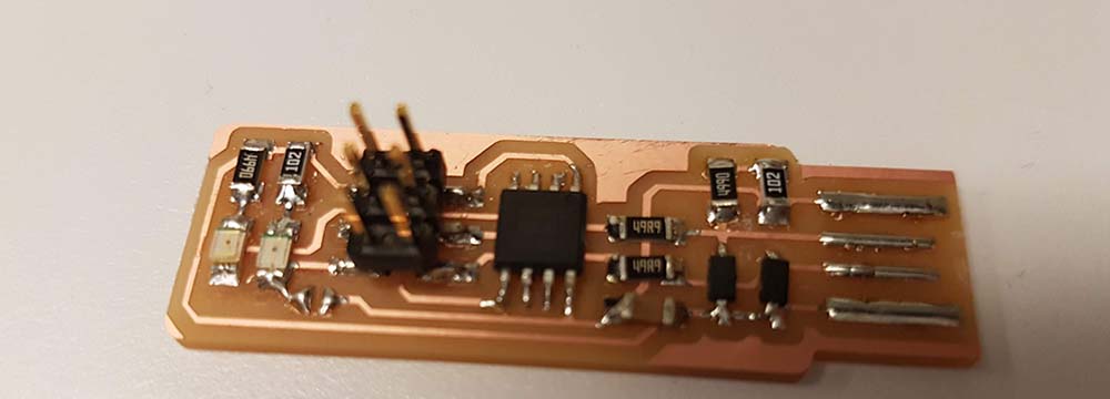
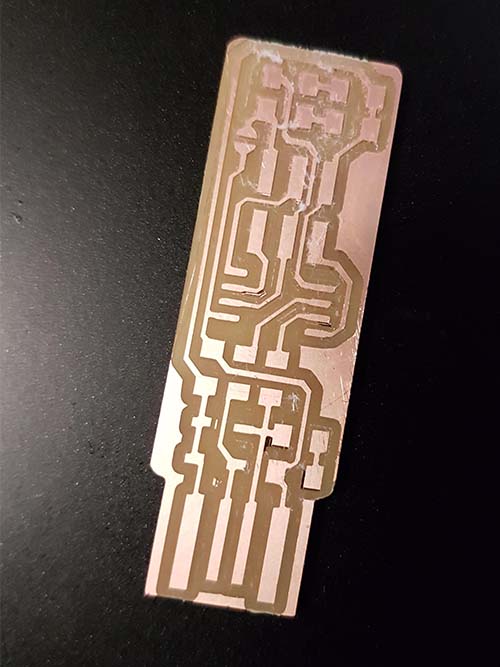
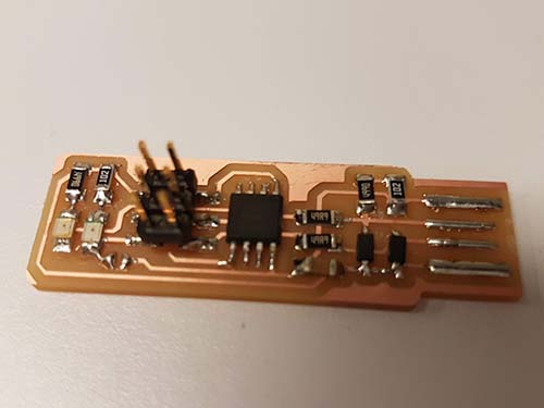
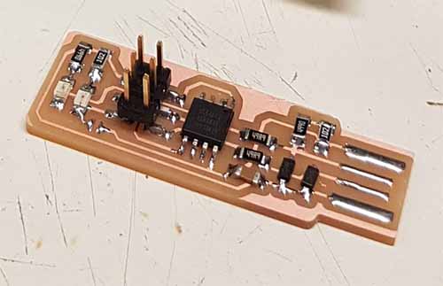
I took a bad milled board and a good one. I gathered all the components from the lab and took it to my lab space to solder the bad milled board as practice. This is the result of the populated board.
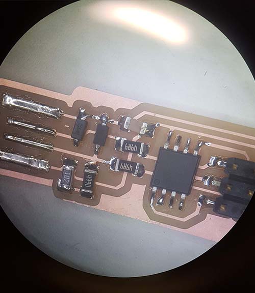
Looking under the microscope, it seems pretty good. No visible mistake or short. I saved one board for soldering in case it does not work when I program it later. Just a clarification, the solder joints are not burned, they just look like that because of the reflection of the light. Another thing I noticed is that there is too much flux in the solder, the board needs to be cleaned.
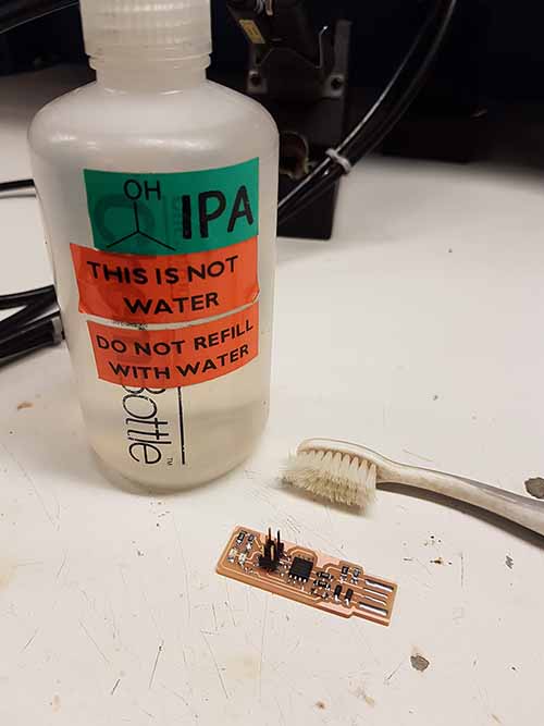
So I cleaned the board a day later with Isopropyl alcohol and a brush. I just pour the alcohol all over the board and started brushing it. The board is clean and shiny now.
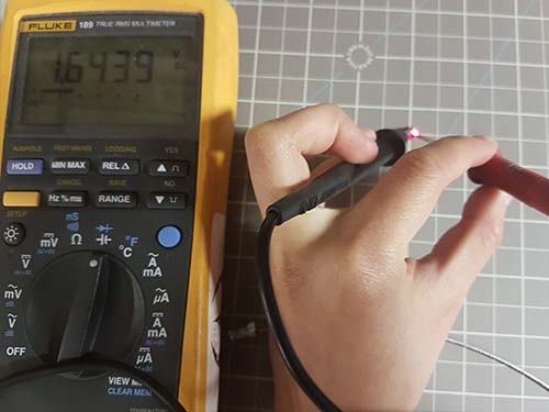
Last comment, you can verify the color of the LED by testing the conductivity with a multimeter. It should not beep if it works. It will also lit up.